2002 CHRYSLER VOYAGER low oil pressure
[x] Cancel search: low oil pressurePage 1469 of 2399
1 second. Therefore, battery voltage is not supplied to
the fuel pump, ignition coil, fuel injectors and heated
oxygen sensors.
ENGINE START-UP MODE
This is an OPEN LOOP mode. If the vehicle is in
park or neutral (automatic transaxles) or the clutch
pedal is depressed (manual transaxles) the ignition
switch energizes the starter relay. The following
actions occur when the starter motor is engaged.
²If the PCM receives the camshaft position sensor
and crankshaft position sensor signals, it energizes
the Auto Shutdown (ASD) relay and fuel pump relay.
If the PCM does not receive both signals within
approximately one second, it will not energize the
ASD relay and fuel pump relay. The ASD and fuel
pump relays supply battery voltage to the fuel pump,
fuel injectors, ignition coil, (EGR solenoid and PCV
heater if equipped) and heated oxygen sensors.
²The PCM energizes the injectors (on the 69É
degree falling edge) for a calculated pulse width until
it determines crankshaft position from the camshaft
position sensor and crankshaft position sensor sig-
nals. The PCM determines crankshaft position within
1 engine revolution.
²After determining crankshaft position, the PCM
begins energizing the injectors in sequence. It adjusts
injector pulse width and controls injector synchroni-
zation by turning the individual ground paths to the
injectors On and Off.
²When the engine idles within 64 RPM of its
target RPM, the PCM compares current MAP sensor
value with the atmospheric pressure value received
during the Ignition Switch On (zero RPM) mode.
Once the ASD and fuel pump relays have been
energized, the PCM determines injector pulse width
based on the following:
²MAP
²Engine RPM
²Battery voltage
²Engine coolant temperature
²Inlet/Intake air temperature (IAT)
²Throttle position
²The number of engine revolutions since cranking
was initiated
During Start-up the PCM maintains ignition tim-
ing at 9É BTDC.
ENGINE WARM-UP MODE
This is an OPEN LOOP mode. The following inputs
are received by the PCM:
²Manifold Absolute Pressure (MAP)
²Crankshaft position (engine speed)
²Engine coolant temperature
²Inlet/Intake air temperature (IAT)
²Camshaft position²Knock sensor
²Throttle position
²A/C switch
²Battery voltage
²Vehicle speed
²Speed control
²O2 sensors
The PCM adjusts injector pulse width and controls
injector synchronization by turning the individual
ground paths to the injectors On and Off.
The PCM adjusts ignition timing and engine idle
speed. Engine idle speed is adjusted through the idle
air control motor.
CRUISE OR IDLE MODE
When the engine is at operating temperature this
is a CLOSED LOOP mode. During cruising or idle
the following inputs are received by the PCM:
²Manifold absolute pressure
²Crankshaft position (engine speed)
²Inlet/Intake air temperature
²Engine coolant temperature
²Camshaft position
²Knock sensor
²Throttle position
²Exhaust gas oxygen content
²A/C control positions
²Battery voltage
²Vehicle speed
The PCM adjusts injector pulse width and controls
injector synchronization by turning the individual
ground paths to the injectors On and Off.
The PCM adjusts engine idle speed and ignition
timing. The PCM adjusts the air/fuel ratio according
to the oxygen content in the exhaust gas (measured
by the upstream and downstream heated oxygen sen-
sor).
The PCM monitors for engine misfire. During
active misfire and depending on the severity, the
PCM either continuously illuminates or flashes the
malfunction indicator lamp (Check Engine light on
instrument panel). Also, the PCM stores an engine
misfire DTC in memory, if 2nd trip with fault.
The PCM performs several diagnostic routines.
They include:
²Oxygen sensor monitor
²Downstream heated oxygen sensor diagnostics
during open loop operation (except for shorted)
²Fuel system monitor
²EGR monitor (if equipped)
²Purge system monitor
²Catalyst efficiency monitor
²All inputs monitored for proper voltage range,
rationality.
²All monitored components (refer to the Emission
section for On-Board Diagnostics).
14 - 18 FUEL INJECTIONRS
FUEL INJECTION (Continued)
ProCarManuals.com
Page 1489 of 2399
Test all fuel supply lines for restrictions or block-
age. Flush or replace as necessary. Bleed fuel system
of air once a fuel supply line has been replaced. Refer
to Air Bleed Procedure for procedures.
To test for fuel line restrictions, a vacuum restric-
tion test may be performed.
HIGH-PRESSURE LINES
Restricted (kinked or bent) high-pressure lines can
cause starting problems, poor engine performance,
engine mis-fire and white smoke from exhaust.
Examine all high-pressure lines for any damage.
Each radius on each high-pressure line must be
smooth and free of any bends or kinks.
Replace damaged, restricted or leaking high-pres-
sure fuel lines with correct replacement line.
CAUTION: High pressure lines cannot contact each
other or other components. Do not attempt to weld
high-pressure fuel lines or to repair lines that are
damaged. If line is kinked or bent, it must be
replaced. Use only recommended lines when
replacement of high-pressure fuel line is necessary.
STANDARD PROCEDURE
STANDARD PROCEDURES - DRAINING WATER
FROM FUEL FILTER
Refer to Fuel Filter/Water Separator removal/in-
stallation for procedures.
STANDARD PROCEDURE - FUEL SYSTEM AIR
PURGE
(1) Remove engine cover (Refer to 9 - ENGINE
COVER - REMOVAL).
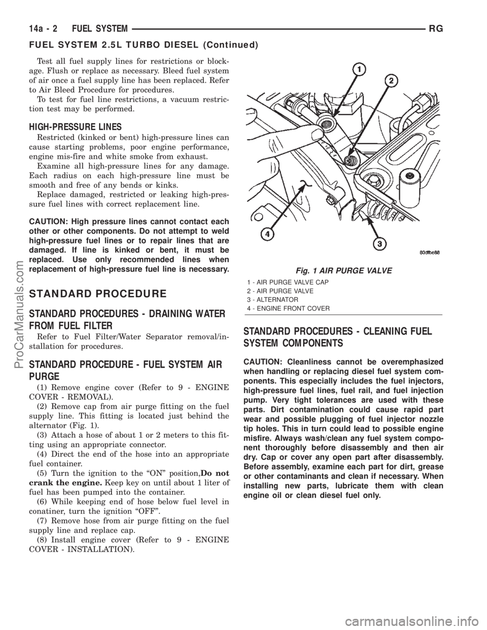
(2) Remove cap from air purge fitting on the fuel
supply line. This fitting is located just behind the
alternator (Fig. 1).
(3) Attach a hose of about 1 or 2 meters to this fit-
ting using an appropriate connector.
(4) Direct the end of the hose into an appropriate
fuel container.
(5) Turn the ignition to the ªONº position,Do not
crank the engine.Keep key on until about 1 liter of
fuel has been pumped into the container.
(6) While keeping end of hose below fuel level in
conatiner, turn the ignition ªOFFº.
(7) Remove hose from air purge fitting on the fuel
supply line and replace cap.
(8) Install engine cover (Refer to 9 - ENGINE
COVER - INSTALLATION).
STANDARD PROCEDURES - CLEANING FUEL
SYSTEM COMPONENTS
CAUTION: Cleanliness cannot be overemphasized
when handling or replacing diesel fuel system com-
ponents. This especially includes the fuel injectors,
high-pressure fuel lines, fuel rail, and fuel injection
pump. Very tight tolerances are used with these
parts. Dirt contamination could cause rapid part
wear and possible plugging of fuel injector nozzle
tip holes. This in turn could lead to possible engine
misfire. Always wash/clean any fuel system compo-
nent thoroughly before disassembly and then air
dry. Cap or cover any open part after disassembly.
Before assembly, examine each part for dirt, grease
or other contaminants and clean if necessary. When
installing new parts, lubricate them with clean
engine oil or clean diesel fuel only.
Fig. 1 AIR PURGE VALVE
1 - AIR PURGE VALVE CAP
2 - AIR PURGE VALVE
3 - ALTERNATOR
4 - ENGINE FRONT COVER
14a - 2 FUEL SYSTEMRG
FUEL SYSTEM 2.5L TURBO DIESEL (Continued)
ProCarManuals.com
Page 1492 of 2399
INSTALLATION - FUEL RAIL
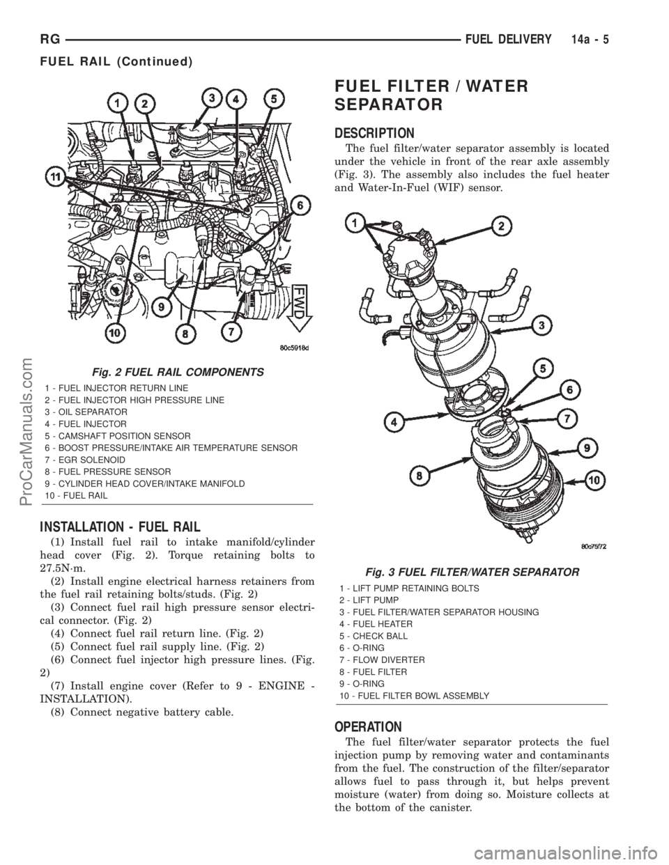
(1) Install fuel rail to intake manifold/cylinder
head cover (Fig. 2). Torque retaining bolts to
27.5N´m.
(2) Install engine electrical harness retainers from
the fuel rail retaining bolts/studs. (Fig. 2)
(3) Connect fuel rail high pressure sensor electri-
cal connector. (Fig. 2)
(4) Connect fuel rail return line. (Fig. 2)
(5) Connect fuel rail supply line. (Fig. 2)
(6) Connect fuel injector high pressure lines. (Fig.
2)
(7) Install engine cover (Refer to 9 - ENGINE -
INSTALLATION).
(8) Connect negative battery cable.
FUEL FILTER / WATER
SEPARATOR
DESCRIPTION
The fuel filter/water separator assembly is located
under the vehicle in front of the rear axle assembly
(Fig. 3). The assembly also includes the fuel heater
and Water-In-Fuel (WIF) sensor.
OPERATION
The fuel filter/water separator protects the fuel
injection pump by removing water and contaminants
from the fuel. The construction of the filter/separator
allows fuel to pass through it, but helps prevent
moisture (water) from doing so. Moisture collects at
the bottom of the canister.
Fig. 2 FUEL RAIL COMPONENTS
1 - FUEL INJECTOR RETURN LINE
2 - FUEL INJECTOR HIGH PRESSURE LINE
3 - OIL SEPARATOR
4 - FUEL INJECTOR
5 - CAMSHAFT POSITION SENSOR
6 - BOOST PRESSURE/INTAKE AIR TEMPERATURE SENSOR
7 - EGR SOLENOID
8 - FUEL PRESSURE SENSOR
9 - CYLINDER HEAD COVER/INTAKE MANIFOLD
10 - FUEL RAIL
Fig. 3 FUEL FILTER/WATER SEPARATOR
1 - LIFT PUMP RETAINING BOLTS
2 - LIFT PUMP
3 - FUEL FILTER/WATER SEPARATOR HOUSING
4 - FUEL HEATER
5 - CHECK BALL
6 - O-RING
7 - FLOW DIVERTER
8 - FUEL FILTER
9 - O-RING
10 - FUEL FILTER BOWL ASSEMBLY
RGFUEL DELIVERY14a-5
FUEL RAIL (Continued)
ProCarManuals.com
Page 1502 of 2399
INTAKE AIR TEMPERATURE
SENSOR
DESCRIPTION
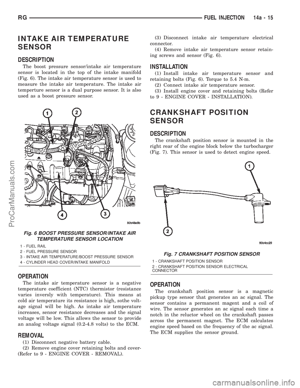
The boost pressure sensor/intake air temperature
sensor is located in the top of the intake manifold
(Fig. 6). The intake air temperature sensor is used to
measure the intake air temperature. The intake air
temperture sensor is a dual purpose sensor. It is also
used as a boost pressure sensor.
OPERATION
The intake air temperature sensor is a negative
temperature coefficient (NTC) thermistor (resistance
varies inversly with temperature). This means at
cold air temperature its resistance is high, sothe volt-
age signal will be high. As intake air temperature
increases, sensor resistance decreases and the signal
voltage will be low. This allows the sensor to provide
an analog voltage signal (0.2-4.8 volts) to the ECM.
REMOVAL
(1) Disconnect negative battery cable.
(2) Remove engine cover retaining bolts and cover-
(Refer to 9 - ENGINE COVER - REMOVAL).(3) Disconnect intake air temperature electrical
connector.
(4) Remove intake air temperature sensor retain-
ing screws and sensor (Fig. 6).
INSTALLATION
(1) Install intake air temperature sensor and
retaining bolts (Fig. 6). Torque to 5.4 N´m.
(2) Connect intake air temperature sensor.
(3) Install engine cover and retaining bolts (Refer
to 9 - ENGINE COVER - INSTALLATION).
CRANKSHAFT POSITION
SENSOR
DESCRIPTION
The crankshaft position sensor is mounted in the
right rear of the engine block below the turbocharger
(Fig. 7). This sensor is used to detect engine speed.
OPERATION
The crankshaft position sensor is a magnetic
pickup type sensor that generates an ac signal. The
sensor contains a permanent magent and a coil of
wire. The sensor generates an ac signal each time a
notch in the reluctor wheel on the crankshaft passes
across the permanent magnet. The ECM calculates
engine speed based on the frequency of the ac signal.
The ECM supplies the sensor ground.
Fig. 6 BOOST PRESSURE SENSOR/INTAKE AIR
TEMPERATURE SENSOR LOCATION
1 - FUEL RAIL
2 - FUEL PRESSURE SENSOR
3 - INTAKE AIR TEMPERATURE/BOOST PRESSURE SENSOR
4 - CYLINDER HEAD COVER/INTAKE MANIFOLD
Fig. 7 CRANKSHAFT POSITION SENSOR
1 - CRANKSHAFT POSITION SENSOR
2 - CRANKSHAFT POSITION SENSOR ELECTRICAL
CONNECTOR
RGFUEL INJECTION14a-15
ProCarManuals.com
Page 1529 of 2399
GEAR
TABLE OF CONTENTS
page page
GEAR
DESCRIPTION.........................26
OPERATION...........................26
WARNING
WARNINGS AND CAUTIONS.............26
REMOVAL
REMOVAL - LHD GEAR.................26
REMOVAL - RHD GEAR................29INSTALLATION
INSTALLATION - LHD GEAR.............32
INSTALLATION - RHD GEAR.............33
SPECIAL TOOLS
POWER STEERING GEAR..............34
OUTER TIE ROD
REMOVAL.............................34
INSTALLATION.........................34
GEAR
DESCRIPTION
This vehicle is equipped with a rack and pinion
power steering gear (Fig. 1). It is mounted to the
underside of the front suspension cradle/crossmem-
ber.
The steering column is attached to the gear
through the use of an intermediate shaft and cou-
plers. The outer ends of the power steering gear's
outer tie rods connect to the steering knuckles.
NOTE: The power steering gear should NOT be ser-
viced or adjusted unless DaimlerChrysler Corpora-
tion authorizes. If a malfunction or oil leak occurs,
the complete steering gear should be replaced.
Only the outer tie rods may be replaced separately
from the rest of the gear.
OPERATION
Turning of the steering wheel is converted into lin-
ear (side-to-side) travel through the meshing of the
helical pinion teeth with the rack teeth in the steer-
ing gear. This travel pushes and pulls the tie rods to
change the direction of the vehicle's front wheels.
Power assist steering provided by the power steer-
ing pump is controlled by an open center, rotary type
control valve which directs oil from the pump to
either side of the integral rack piston upon demand.
Road feel is controlled by the diameter of a torsion
bar which initially steers the vehicle. As required
steering effort increases, as in a turn, the torsion bar
twists, causing relative rotary motion between the
rotary valve body and the valve spool. This move-
ment directs oil behind the integral rack piston
which, in turn, builds hydraulic pressure and assists
in the turning effort.Manual steering control of the vehicle can be main-
tained if power steering assist is lost. However,
under this condition, steering effort is significantly
increased.
WARNING
WARNINGS AND CAUTIONS
WARNING: POWER STEERING FLUID, ENGINE
PARTS AND EXHAUST SYSTEM MAY BE
EXTREMELY HOT IF ENGINE HAS BEEN RUNNING.
DO NOT START ENGINE WITH ANY LOOSE OR DIS-
CONNECTED HOSES. DO NOT ALLOW HOSES TO
TOUCH HOT EXHAUST MANIFOLD OR CATALYST.
WARNING: FLUID LEVEL SHOULD BE CHECKED
WITH THE ENGINE OFF TO PREVENT PERSONAL
INJURY FROM MOVING PARTS.
CAUTION: When the system is open, cap all open
ends of the hoses, power steering pump fittings or
power steering gear ports to prevent entry of for-
eign material into the components.
REMOVAL
REMOVAL - LHD GEAR
(1) Remove cap from power steering fluid reser-
voir.
(2) Using a siphon pump, remove as much fluid as
possible from the power steering fluid reservoir.Use
care not to damage the filter mesh below the
fluid surface.
19 - 26 GEARRS
ProCarManuals.com
Page 1552 of 2399
(10) Tighten hose tube nut at power steering gear
port to 31 N´m (275 in. lbs.) torque.
(11) Install front emissions vapor canister. (Refer
to 25 - EMISSIONS CONTROL/EVAPORATIVE
EMISSIONS/VAPOR CANISTER - INSTALLATION)
(12) Lower vehicle.
(13) Fill and bleed the power steering system
using the Power Steering Pump Initial Operation
Procedure. (Refer to 19 - STEERING/PUMP - STAN-
DARD PROCEDURE)
(14) Inspect system for leaks.
HOSE - POWER STEERING
RETURN
REMOVAL
REMOVAL - 2.4L ENGINE
NOTE: Before proceeding, review all WARNINGS
and CAUTIONS. (Refer to 19 - STEERING/PUMP -
WARNING)(Refer to 19 - STEERING/PUMP - CAU-
TION)
(1) Remove cap from power steering fluid reser-
voir.
(2) Using a siphon pump, remove as much power
steering fluid as possible from power steering fluid
reservoir.
(3) Raise vehicle. (Refer to LUBRICATION &
MAINTENANCE/HOISTING - STANDARD PROCE-
DURE)
(4) Remove front emissions vapor canister. (Refer
to 25 - EMISSIONS CONTROL/EVAPORATIVE
EMISSIONS/VAPOR CANISTER - REMOVAL)
(5) Place an oil drain pan under vehicle to catch
power steering fluid.
(6) Cut tie-strap securing insulating heat sleeve to
power steering fluid return hose near power steering
pump. Pull back heat sleeve to expose hose clamp.
(7) Remove clamp, then return hose from power
steering pump (Fig. 19).
(8) Remove 2 bolts attaching power steering cooler
to cradle crossmember reinforcement (Fig. 23).
(9) Remove bolts attaching routing clamps to front
suspension cradle crossmember (Fig. 19). Remove
return hose from clamps.
(10) Back out return hose tube nut at power steer-
ing gear and remove hose (Fig. 19).
REMOVAL - 3.3L/3.8L ENGINE
NOTE:Before proceeding, review all WARNINGS and
CAUTIONS. (Refer to 19 - STEERING/PUMP - WARNIN-
G)(Refer to 19 - STEERING/PUMP - CAUTION)
(1) Remove cap from power steering fluid reser-
voir.
(2) Using a siphon pump, remove as much power
steering fluid as possible from power steering fluid
reservoir.
(3) Place an oil drain pan under vehicle to catch
any draining power steering fluid.
(4) Remove clamp attaching return hose to power
steering fluid reservoir. Disconnect hose from reser-
voir (Fig. 21).
(5) Follow return hose downward and open
retainer at ABS bracket (Fig. 20). Remove hose tube
from retainer.
(6) Raise vehicle. (Refer to LUBRICATION &
MAINTENANCE/HOISTING - STANDARD PROCE-
DURE)
(7) Remove front emissions vapor canister. (Refer
to 25 - EMISSIONS CONTROL/EVAPORATIVE
EMISSIONS/VAPOR CANISTER - REMOVAL)
(8) Remove bolt securing return hose routing
clamp to suspension cradle crossmember (Fig. 20).
(9) Remove 2 bolts attaching power steering cooler
to cradle crossmember reinforcement (Fig. 23).
(10) Disconnect return hose at power steering gear
(Fig. 20).
(11) Remove power steering fluid return hose with
cooler from vehicle.
Fig. 23 POWER STEERING COOLER
1 - CRADLE CROSSMEMBER REINFORCEMENT
2 - POWER STEERING COOLER
RSPUMP19-49
HOSE - POWER STEERING PRESSURE (Continued)
ProCarManuals.com
Page 1578 of 2399
31TH AUTOMATIC TRANSAXLE
TABLE OF CONTENTS
page page
31TH AUTOMATIC TRANSAXLE
DESCRIPTION.........................22
OPERATION...........................24
DIAGNOSIS AND TESTING
DIAGNOSIS AND TESTING - PRELIMINARY
DIAGNOSIS..........................24
DIAGNOSIS AND TESTING - ROAD TEST . . . 31
DIAGNOSIS AND TESTING - HYDRAULIC
PRESSURE TESTS....................32
DIAGNOSIS AND TESTING - TORQUE
CONVERTER HOUSING FLUID LEAKAGE . . . 35
DIAGNOSIS AND TESTING - CLUTCH AND
SERVO AIR PRESSURE TESTS..........35
STANDARD PROCEDURE - ALUMINUM
THREAD REPAIR......................37
REMOVAL.............................37
DISASSEMBLY.........................40
ASSEMBLY............................51
INSTALLATION.........................61
SCHEMATICS AND DIAGRAMS
31TH TRANSAXLE HYDRAULIC
SCHEMATICS........................64
SPECIFICATIONS
31TH AUTOMATIC TRANSAXLE..........72
SPECIAL TOOLS
31TH AUTOMATIC TRANSAXLE..........75
ACCUMULATOR
DESCRIPTION.........................79
OPERATION...........................79
BANDS
DESCRIPTION
KICKDOWN (FRONT) BAND.............80
OPERATION
LOW/REVERSE (REAR) BAND...........80
ADJUSTMENTS
ADJUSTMENT - FRONT BAND...........80
ADJUSTMENTS - REAR BAND...........80
CLUTCH - FRONT
DESCRIPTION.........................82
OPERATION...........................82
DISASSEMBLY.........................82
ASSEMBLY............................84
CLUTCH - REAR
DESCRIPTION.........................86
OPERATION...........................86
DISASSEMBLY.........................87
ASSEMBLY............................89
FINAL DRIVE
DISASSEMBLY.........................91
ASSEMBLY............................94ADJUSTMENTS
ADJUSTMENT - DIFFERENTIAL BEARING . . 97
FLUID
STANDARD PROCEDURE
STANDARD PROCEDURE - FLUID LEVEL
AND CONDITION CHECK...............99
STANDARD PROCEDURE - FLUID AND
FILTER CHANGE......................99
GEAR SHIFT CABLE
REMOVAL............................101
INSTALLATION........................102
ADJUSTMENTS
GEARSHIFT CABLE ADJUSTMENT.......104
GOVERNOR
DESCRIPTION........................104
OPERATION..........................104
CLEANING...........................104
INSPECTION.........................104
OIL PUMP
DESCRIPTION........................105
OPERATION..........................105
STANDARD PROCEDURE - OIL PUMP
VOLUME CHECK.....................105
DISASSEMBLY........................106
CLEANING...........................106
INSPECTION.........................106
ASSEMBLY...........................107
PARK/NEUTRAL POSITION SWITCH
DIAGNOSIS AND TESTING - PARK/NEUTRAL
POSITION SWITCH...................107
REMOVAL............................107
INSTALLATION........................107
PLANETARY GEARTRAIN
DISASSEMBLY........................108
ASSEMBLY...........................109
SEAL - OIL PUMP
REMOVAL............................110
INSTALLATION........................110
SERVO - KICKDOWN
DESCRIPTION........................111
OPERATION..........................111
DISASSEMBLY........................111
CLEANING...........................112
INSPECTION..........................113
ASSEMBLY...........................113
SERVO - LOW/REVERSE
DESCRIPTION........................113
OPERATION..........................113
DISASSEMBLY........................114
CLEANING...........................114
RS31TH AUTOMATIC TRANSAXLE21-21
ProCarManuals.com
Page 1579 of 2399
ASSEMBLY...........................115
SHIFT INTERLOCK SOLENOID
DESCRIPTION........................115
OPERATION..........................115
DIAGNOSIS AND TESTING - BRAKE/
TRANSMISSION SHIFT INTERLOCK
SOLENOID..........................117
REMOVAL............................117
INSTALLATION........................118
SOLENOID - TCC
DESCRIPTION........................119
OPERATION..........................119
REMOVAL............................119
INSTALLATION........................120
THROTTLE VALVE CABLE
REMOVAL............................120
INSTALLATION........................121
ADJUSTMENTS
THROTTLE VALVE LINKAGE
ADJUSTMENT.......................122
TORQUE CONVERTER
DESCRIPTION........................122
OPERATION..........................126
REMOVAL............................127
INSTALLATION........................127
TRANSFER SYSTEM - OUTPUT SHAFT/GEAR/
BEARING
REMOVAL............................128INSTALLATION........................131
ADJUSTMENTS
ADJUSTMENT - OUTPUT SHAFT BEARING . 135
TRANSFER SYSTEM - TRANSFER SHAFT/
GEAR/BEARING
REMOVAL............................137
INSTALLATION........................141
ADJUSTMENTS
ADJUSTMENT - TRANSFER SHAFT
BEARING...........................145
VALVE BODY
REMOVAL............................146
DISASSEMBLY........................148
CLEANING...........................154
INSPECTION.........................155
ASSEMBLY...........................155
INSTALLATION........................158
ADJUSTMENTS
HYDRAULIC CONTROL PRESSURE
ADJUSTMENTS......................160
VEHICLE SPEED SENSOR/PINION GEAR
REMOVAL............................160
INSTALLATION........................160
31TH AUTOMATIC
TRANSAXLE
DESCRIPTION
This transaxle combines torque converter, three
speed transmission, final drive gearing, and differen-
tial into a front wheel drive system.
Within this transaxle, there are three primary
areas:
(1) Main center line plus valve body.
(2) Transfer shaft center line (includes governor
and parking sprag).
(3) Differential center line.
Center distances between the main rotating parts
in these three areas are held precise to maintain a
low noise level.
The torque converter, transaxle area, and differen-
tial are housed in an integral aluminum die casting.
The differential oil sump is common with the
transaxle sump. Separate filling of the differen-
tial is NOT necessary.
The torque converter is attached to the crankshaft
through a flexible driving plate. Cooling of the con-
verter is accomplished by circulating the transaxle
fluid through a remote cooler. There are two types of
coolers used. An oil-to-water type cooler located in
the radiator side tank and/or an oil-to-air heatexchanger. The torque converter assembly is a sealed
unit that cannot be disassembled.
The transaxle fluid is filtered by an internal filter
attached to the lower side of the valve body assembly.
Engine torque is transmitted to the torque con-
verter and then through the input shaft to multiple-
disc clutches in the transaxle. The power flow
depends on the application of the clutches and bands.
Refer to Elements in Use Chart in Diagnosis and
Tests section.
The transaxle consists of:
²Two multiple-disc clutches
²An overrunning clutch
²Two servos
²A hydraulic accumulator
²Two bands
²Two planetary gear sets
This provides three forward ratios and a reverse
ratio. The common sun gear of the planetary gear
sets is connected to the front clutch by a driving
shell. The driving shell is splined to the sun gear and
front clutch retainer. The hydraulic system consists
of an oil pump and a single valve body which con-
tains all of the valves except the governor valves.
The transaxle sump and differential sump are both
vented through the dipstick. Output torque from the
main center line is delivered through helical gears to
the transfer shaft. This gear set is a factor in the
transaxle final drive (axle) ratio. The shaft also car-
21 - 22 31TH AUTOMATIC TRANSAXLERS
ProCarManuals.com