2002 CHRYSLER VOYAGER low oil pressure
[x] Cancel search: low oil pressurePage 1656 of 2399
FLUID
STANDARD PROCEDURE
STANDARD PROCEDURE - FLUID LEVEL AND
CONDITION CHECK
NOTE: The transmission and differential sump have
a common oil sump with a communicating opening
between the two.
FLUID LEVEL CHECK
The torque converter fills in both the P Park and N
Neutral positions. Place the selector lever in P Park
to be sure that the fluid level check is accurate.The
engine should be running at idle speed for at
least one minute, with the vehicle on level
ground. This will assure complete oil level sta-
bilization between differential and transmis-
sion.The fluid should be at normal operating
temperature (approximately 82 C. or 180 F.). The
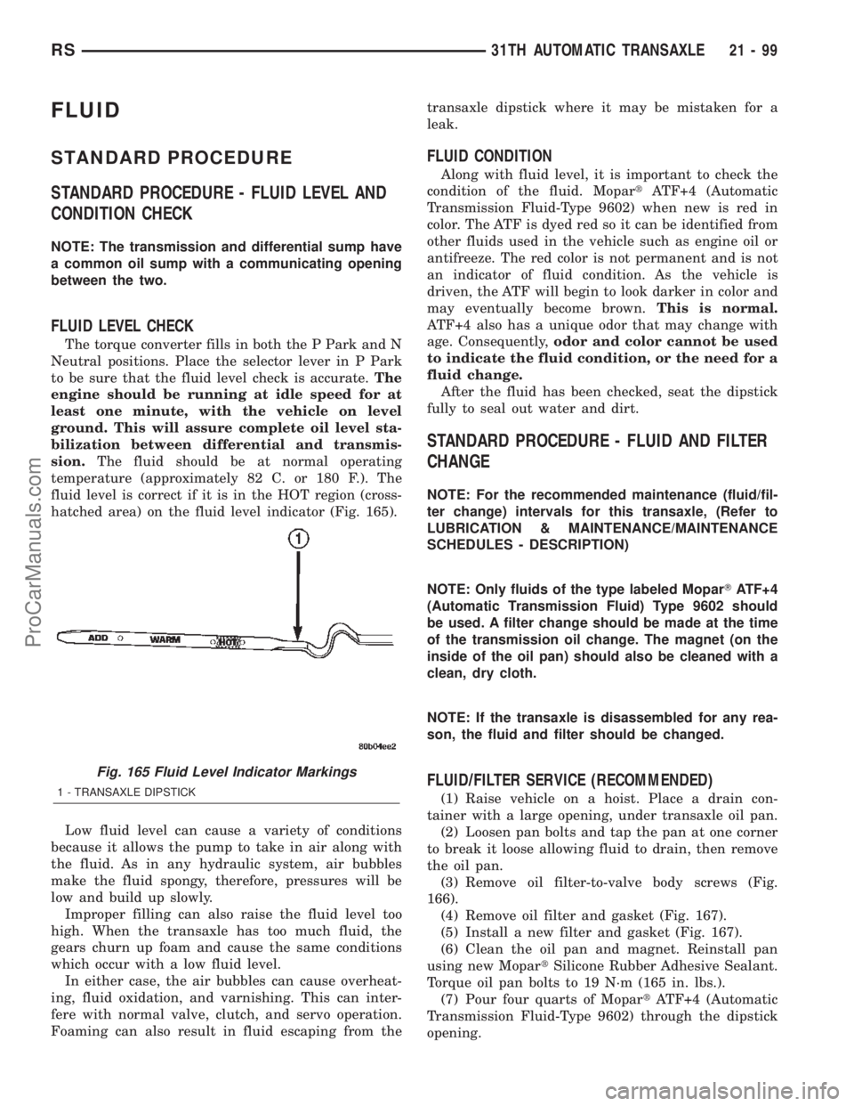
fluid level is correct if it is in the HOT region (cross-
hatched area) on the fluid level indicator (Fig. 165).
Low fluid level can cause a variety of conditions
because it allows the pump to take in air along with
the fluid. As in any hydraulic system, air bubbles
make the fluid spongy, therefore, pressures will be
low and build up slowly.
Improper filling can also raise the fluid level too
high. When the transaxle has too much fluid, the
gears churn up foam and cause the same conditions
which occur with a low fluid level.
In either case, the air bubbles can cause overheat-
ing, fluid oxidation, and varnishing. This can inter-
fere with normal valve, clutch, and servo operation.
Foaming can also result in fluid escaping from thetransaxle dipstick where it may be mistaken for a
leak.
FLUID CONDITION
Along with fluid level, it is important to check the
condition of the fluid. MopartATF+4 (Automatic
Transmission Fluid-Type 9602) when new is red in
color. The ATF is dyed red so it can be identified from
other fluids used in the vehicle such as engine oil or
antifreeze. The red color is not permanent and is not
an indicator of fluid condition. As the vehicle is
driven, the ATF will begin to look darker in color and
may eventually become brown.This is normal.
ATF+4 also has a unique odor that may change with
age. Consequently,odor and color cannot be used
to indicate the fluid condition, or the need for a
fluid change.
After the fluid has been checked, seat the dipstick
fully to seal out water and dirt.
STANDARD PROCEDURE - FLUID AND FILTER
CHANGE
NOTE: For the recommended maintenance (fluid/fil-
ter change) intervals for this transaxle, (Refer to
LUBRICATION & MAINTENANCE/MAINTENANCE
SCHEDULES - DESCRIPTION)
NOTE: Only fluids of the type labeled MoparTATF+4
(Automatic Transmission Fluid) Type 9602 should
be used. A filter change should be made at the time
of the transmission oil change. The magnet (on the
inside of the oil pan) should also be cleaned with a
clean, dry cloth.
NOTE: If the transaxle is disassembled for any rea-
son, the fluid and filter should be changed.
FLUID/FILTER SERVICE (RECOMMENDED)
(1) Raise vehicle on a hoist. Place a drain con-
tainer with a large opening, under transaxle oil pan.
(2) Loosen pan bolts and tap the pan at one corner
to break it loose allowing fluid to drain, then remove
the oil pan.
(3) Remove oil filter-to-valve body screws (Fig.
166).
(4) Remove oil filter and gasket (Fig. 167).
(5) Install a new filter and gasket (Fig. 167).
(6) Clean the oil pan and magnet. Reinstall pan
using new MopartSilicone Rubber Adhesive Sealant.
Torque oil pan bolts to 19 N´m (165 in. lbs.).
(7) Pour four quarts of MopartATF+4 (Automatic
Transmission Fluid-Type 9602) through the dipstick
opening.
Fig. 165 Fluid Level Indicator Markings
1 - TRANSAXLE DIPSTICK
RS31TH AUTOMATIC TRANSAXLE21-99
ProCarManuals.com
Page 1668 of 2399
SERVO - KICKDOWN
DESCRIPTION
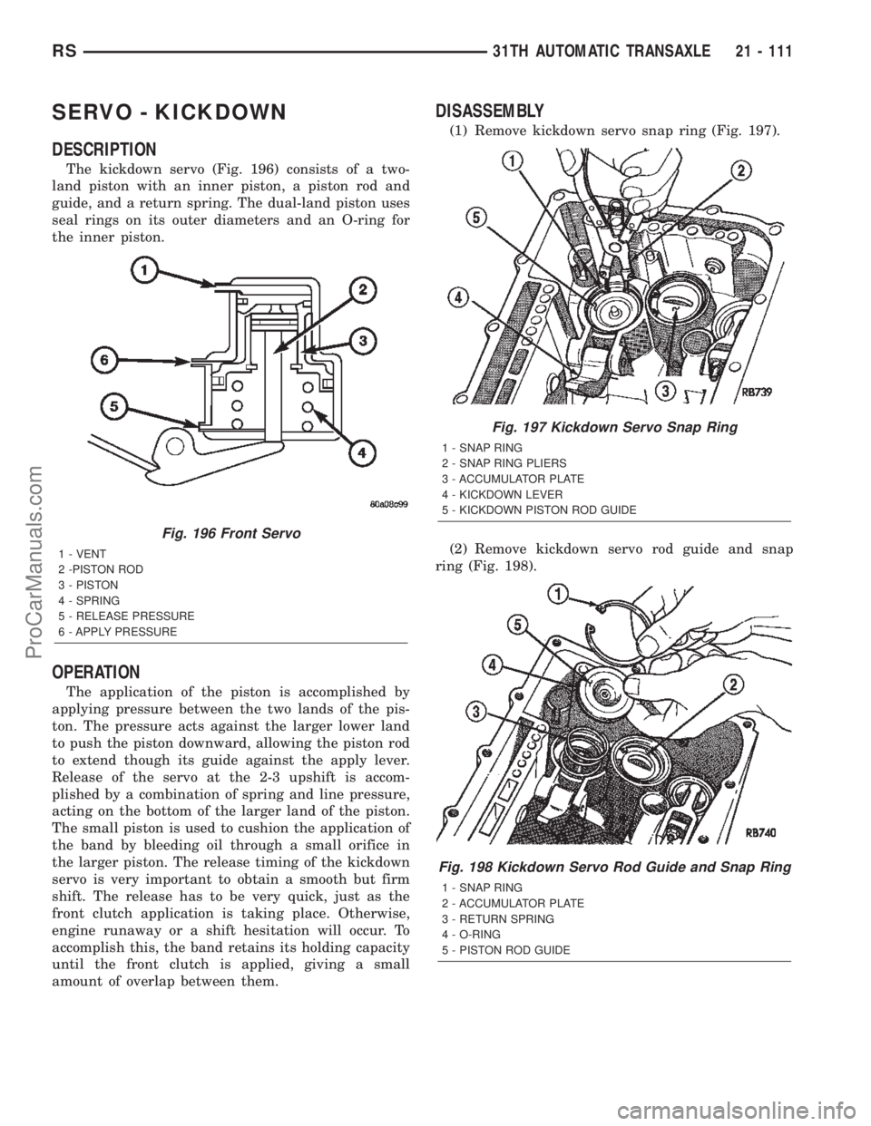
The kickdown servo (Fig. 196) consists of a two-
land piston with an inner piston, a piston rod and
guide, and a return spring. The dual-land piston uses
seal rings on its outer diameters and an O-ring for
the inner piston.
OPERATION
The application of the piston is accomplished by
applying pressure between the two lands of the pis-
ton. The pressure acts against the larger lower land
to push the piston downward, allowing the piston rod
to extend though its guide against the apply lever.
Release of the servo at the 2-3 upshift is accom-
plished by a combination of spring and line pressure,
acting on the bottom of the larger land of the piston.
The small piston is used to cushion the application of
the band by bleeding oil through a small orifice in
the larger piston. The release timing of the kickdown
servo is very important to obtain a smooth but firm
shift. The release has to be very quick, just as the
front clutch application is taking place. Otherwise,
engine runaway or a shift hesitation will occur. To
accomplish this, the band retains its holding capacity
until the front clutch is applied, giving a small
amount of overlap between them.
DISASSEMBLY
(1) Remove kickdown servo snap ring (Fig. 197).
(2) Remove kickdown servo rod guide and snap
ring (Fig. 198).
Fig. 196 Front Servo
1 - VENT
2 -PISTON ROD
3 - PISTON
4 - SPRING
5 - RELEASE PRESSURE
6 - APPLY PRESSURE
Fig. 197 Kickdown Servo Snap Ring
1 - SNAP RING
2 - SNAP RING PLIERS
3 - ACCUMULATOR PLATE
4 - KICKDOWN LEVER
5 - KICKDOWN PISTON ROD GUIDE
Fig. 198 Kickdown Servo Rod Guide and Snap Ring
1 - SNAP RING
2 - ACCUMULATOR PLATE
3 - RETURN SPRING
4 - O-RING
5 - PISTON ROD GUIDE
RS31TH AUTOMATIC TRANSAXLE21 - 111
ProCarManuals.com
Page 1717 of 2399
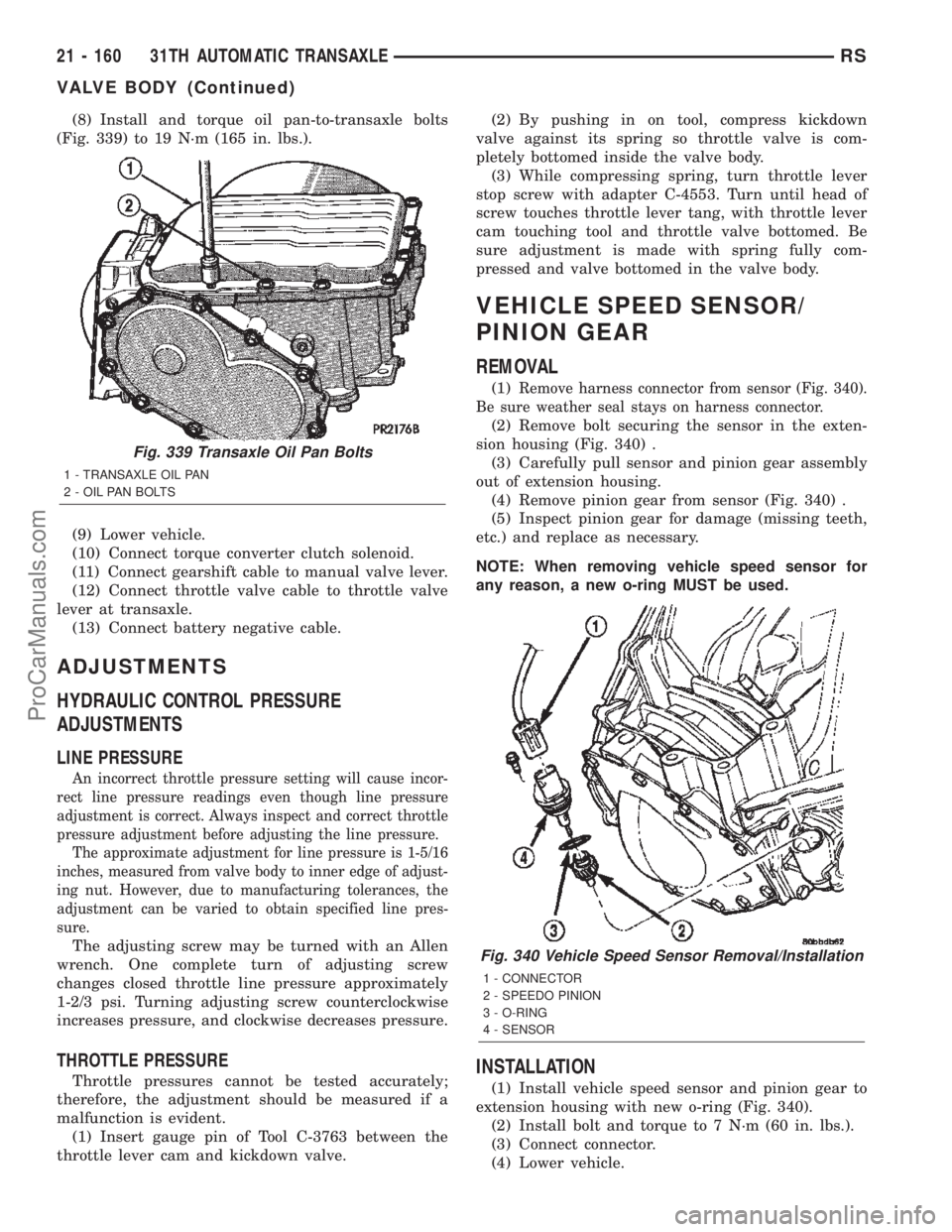
(8) Install and torque oil pan-to-transaxle bolts
(Fig. 339) to 19 N´m (165 in. lbs.).
(9) Lower vehicle.
(10) Connect torque converter clutch solenoid.
(11) Connect gearshift cable to manual valve lever.
(12) Connect throttle valve cable to throttle valve
lever at transaxle.
(13) Connect battery negative cable.
ADJUSTMENTS
HYDRAULIC CONTROL PRESSURE
ADJUSTMENTS
LINE PRESSURE
An incorrect throttle pressure setting will cause incor-
rect line pressure readings even though line pressure
adjustment is correct. Always inspect and correct throttle
pressure adjustment before adjusting the line pressure.
The approximate adjustment for line pressure is 1-5/16
inches, measured from valve body to inner edge of adjust-
ing nut. However, due to manufacturing tolerances, the
adjustment can be varied to obtain specified line pres-
sure.
The adjusting screw may be turned with an Allen
wrench. One complete turn of adjusting screw
changes closed throttle line pressure approximately
1-2/3 psi. Turning adjusting screw counterclockwise
increases pressure, and clockwise decreases pressure.
THROTTLE PRESSURE
Throttle pressures cannot be tested accurately;
therefore, the adjustment should be measured if a
malfunction is evident.
(1) Insert gauge pin of Tool C-3763 between the
throttle lever cam and kickdown valve.(2) By pushing in on tool, compress kickdown
valve against its spring so throttle valve is com-
pletely bottomed inside the valve body.
(3) While compressing spring, turn throttle lever
stop screw with adapter C-4553. Turn until head of
screw touches throttle lever tang, with throttle lever
cam touching tool and throttle valve bottomed. Be
sure adjustment is made with spring fully com-
pressed and valve bottomed in the valve body.
VEHICLE SPEED SENSOR/
PINION GEAR
REMOVAL
(1)Remove harness connector from sensor (Fig. 340).
Be sure weather seal stays on harness connector.
(2) Remove bolt securing the sensor in the exten-
sion housing (Fig. 340) .
(3) Carefully pull sensor and pinion gear assembly
out of extension housing.
(4) Remove pinion gear from sensor (Fig. 340) .
(5) Inspect pinion gear for damage (missing teeth,
etc.) and replace as necessary.
NOTE: When removing vehicle speed sensor for
any reason, a new o-ring MUST be used.
INSTALLATION
(1) Install vehicle speed sensor and pinion gear to
extension housing with new o-ring (Fig. 340).
(2) Install bolt and torque to 7 N´m (60 in. lbs.).
(3) Connect connector.
(4) Lower vehicle.
Fig. 339 Transaxle Oil Pan Bolts
1 - TRANSAXLE OIL PAN
2 - OIL PAN BOLTS
Fig. 340 Vehicle Speed Sensor Removal/Installation
1 - CONNECTOR
2 - SPEEDO PINION
3 - O-RING
4 - SENSOR
21 - 160 31TH AUTOMATIC TRANSAXLERS
VALVE BODY (Continued)
ProCarManuals.com
Page 1719 of 2399
OPERATION..........................292
REMOVAL............................292
INSTALLATION........................292
TRD LINK
DESCRIPTION........................292
OPERATION..........................292
VALVE BODY
DESCRIPTION........................293OPERATION..........................293
REMOVAL
REMOVAL..........................294
REMOVAL..........................296
DISASSEMBLY........................297
ASSEMBLY...........................301
INSTALLATION........................306
41TE AUTOMATIC
TRANSAXLE
DESCRIPTION
The 41TE (Fig. 1) is a four-speed transaxle that is
a conventional hydraulic/mechanical assembly with
an integral differential, and is controlled with adap-
tive electronic controls and monitors. The hydraulic
system of the transaxle consists of the transaxle
fluid, fluid passages, hydraulic valves, and various
line pressure control components. An input clutch
assembly which houses the underdrive, overdrive,
and reverse clutches is used. It also utilizes separate
holding clutches: 2nd/4th gear and Low/Reverse. The
primary mechanical components of the transaxle con-
sist of the following:
²Three multiple disc input clutches
²Two multiple disc holding clutches
²Four hydraulic accumulators
²Two planetary gear sets
²Hydraulic oil pump²Valve body
²Solenoid/Pressure switch assembly
²Integral differential assembly
Control of the transaxle is accomplished by fully
adaptive electronics. Optimum shift scheduling is
accomplished through continuous real-time sensor
feedback information provided to the Transmission
Control Module (TCM).
The TCM is the heart of the electronic control sys-
tem and relies on information from various direct
and indirect inputs (sensors, switches, etc.) to deter-
mine driver demand and vehicle operating condi-
tions. With this information, the TCM can calculate
and perform timely and quality shifts through vari-
ous output or control devices (solenoid pack, trans-
mission control relay, etc.).
The TCM also performs certain self-diagnostic
functions and provides comprehensive information
(sensor data, DTC's, etc.) which is helpful in proper
diagnosis and repair. This information can be viewed
with the DRB scan tool.
21 - 162 41TE AUTOMATIC TRANSAXLERS
ProCarManuals.com
Page 1725 of 2399
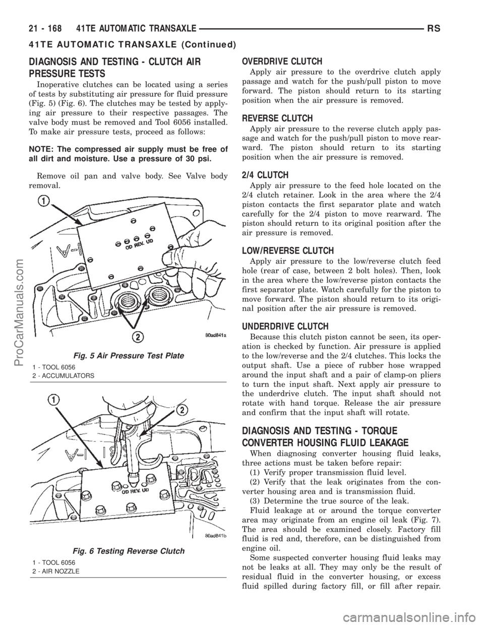
DIAGNOSIS AND TESTING - CLUTCH AIR
PRESSURE TESTS
Inoperative clutches can be located using a series
of tests by substituting air pressure for fluid pressure
(Fig. 5) (Fig. 6). The clutches may be tested by apply-
ing air pressure to their respective passages. The
valve body must be removed and Tool 6056 installed.
To make air pressure tests, proceed as follows:
NOTE: The compressed air supply must be free of
all dirt and moisture. Use a pressure of 30 psi.
Remove oil pan and valve body. See Valve body
removal.
OVERDRIVE CLUTCH
Apply air pressure to the overdrive clutch apply
passage and watch for the push/pull piston to move
forward. The piston should return to its starting
position when the air pressure is removed.
REVERSE CLUTCH
Apply air pressure to the reverse clutch apply pas-
sage and watch for the push/pull piston to move rear-
ward. The piston should return to its starting
position when the air pressure is removed.
2/4 CLUTCH
Apply air pressure to the feed hole located on the
2/4 clutch retainer. Look in the area where the 2/4
piston contacts the first separator plate and watch
carefully for the 2/4 piston to move rearward. The
piston should return to its original position after the
air pressure is removed.
LOW/REVERSE CLUTCH
Apply air pressure to the low/reverse clutch feed
hole (rear of case, between 2 bolt holes). Then, look
in the area where the low/reverse piston contacts the
first separator plate. Watch carefully for the piston to
move forward. The piston should return to its origi-
nal position after the air pressure is removed.
UNDERDRIVE CLUTCH
Because this clutch piston cannot be seen, its oper-
ation is checked by function. Air pressure is applied
to the low/reverse and the 2/4 clutches. This locks the
output shaft. Use a piece of rubber hose wrapped
around the input shaft and a pair of clamp-on pliers
to turn the input shaft. Next apply air pressure to
the underdrive clutch. The input shaft should not
rotate with hand torque. Release the air pressure
and confirm that the input shaft will rotate.
DIAGNOSIS AND TESTING - TORQUE
CONVERTER HOUSING FLUID LEAKAGE
When diagnosing converter housing fluid leaks,
three actions must be taken before repair:
(1) Verify proper transmission fluid level.
(2) Verify that the leak originates from the con-
verter housing area and is transmission fluid.
(3) Determine the true source of the leak.
Fluid leakage at or around the torque converter
area may originate from an engine oil leak (Fig. 7).
The area should be examined closely. Factory fill
fluid is red and, therefore, can be distinguished from
engine oil.
Some suspected converter housing fluid leaks may
not be leaks at all. They may only be the result of
residual fluid in the converter housing, or excess
fluid spilled during factory fill, or fill after repair.
Fig. 5 Air Pressure Test Plate
1 - TOOL 6056
2 - ACCUMULATORS
Fig. 6 Testing Reverse Clutch
1 - TOOL 6056
2 - AIR NOZZLE
21 - 168 41TE AUTOMATIC TRANSAXLERS
41TE AUTOMATIC TRANSAXLE (Continued)
ProCarManuals.com
Page 1727 of 2399
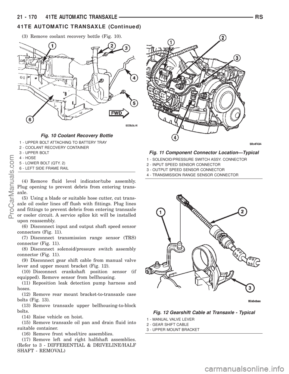
(3) Remove coolant recovery bottle (Fig. 10).
(4) Remove fluid level indicator/tube assembly.
Plug opening to prevent debris from entering trans-
axle.
(5) Using a blade or suitable hose cutter, cut trans-
axle oil cooler lines off flush with fittings. Plug lines
and fittings to prevent debris from entering transaxle
or cooler circuit. A service splice kit will be installed
upon reassembly.
(6) Disconnect input and output shaft speed sensor
connectors (Fig. 11).
(7) Disconnect transmission range sensor (TRS)
connector (Fig. 11).
(8) Disconnect solenoid/pressure switch assembly
connector (Fig. 11).
(9) Disconnect gear shift cable from manual valve
lever and upper mount bracket (Fig. 12).
(10) Disconnect crankshaft position sensor (if
equipped). Remove sensor from bellhousing.
(11) Reposition leak detection pump harness and
hoses.
(12) Remove rear mount bracket-to-transaxle case
bolts (Fig. 13).
(13) Remove transaxle upper bellhousing-to-block
bolts.
(14) Raise vehicle on hoist.
(15) Remove transaxle oil pan and drain fluid into
suitable container.
(16) Remove front wheel/tire assemblies.
(17) Remove left and right halfshaft assemblies.
(Refer to 3 - DIFFERENTIAL & DRIVELINE/HALF
SHAFT - REMOVAL)
Fig. 10 Coolant Recovery Bottle
1 - UPPER BOLT ATTACHING TO BATTERY TRAY
2 - COOLANT RECOVERY CONTAINER
3 - UPPER BOLT
4 - HOSE
5 - LOWER BOLT (QTY. 2)
6 - LEFT SIDE FRAME RAIL
Fig. 11 Component Connector LocationÐTypical
1 - SOLENOID/PRESSURE SWITCH ASSY. CONNECTOR
2 - INPUT SPEED SENSOR CONNECTOR
3 - OUTPUT SPEED SENSOR CONNECTOR
4 - TRANSMISSION RANGE SENSOR CONNECTOR
Fig. 12 Gearshift Cable at Transaxle - Typical
1 - MANUAL VALVE LEVER
2 - GEAR SHIFT CABLE
3 - UPPER MOUNT BRACKET
21 - 170 41TE AUTOMATIC TRANSAXLERS
41TE AUTOMATIC TRANSAXLE (Continued)
ProCarManuals.com
Page 1728 of 2399
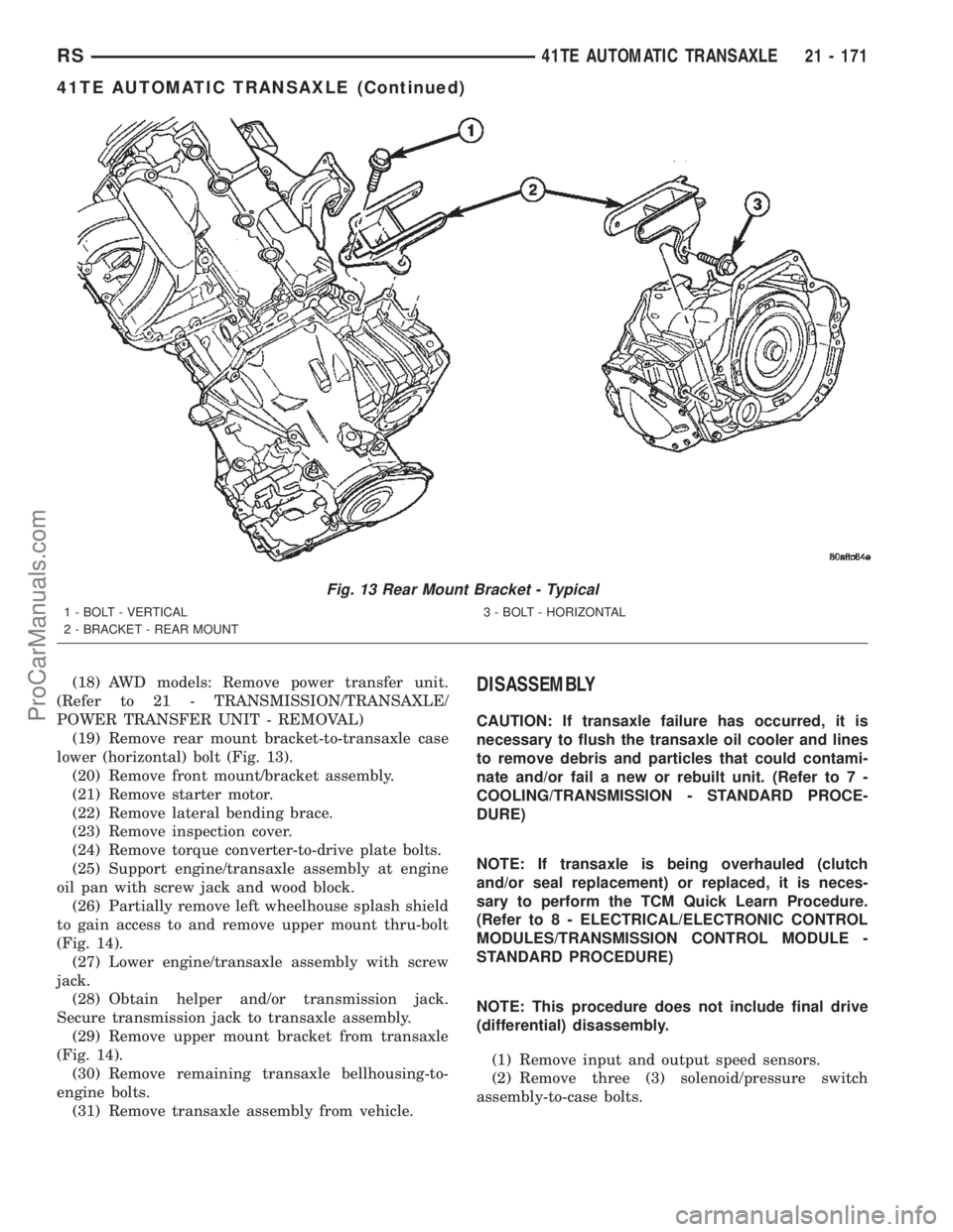
(18) AWD models: Remove power transfer unit.
(Refer to 21 - TRANSMISSION/TRANSAXLE/
POWER TRANSFER UNIT - REMOVAL)
(19) Remove rear mount bracket-to-transaxle case
lower (horizontal) bolt (Fig. 13).
(20) Remove front mount/bracket assembly.
(21) Remove starter motor.
(22) Remove lateral bending brace.
(23) Remove inspection cover.
(24) Remove torque converter-to-drive plate bolts.
(25) Support engine/transaxle assembly at engine
oil pan with screw jack and wood block.
(26) Partially remove left wheelhouse splash shield
to gain access to and remove upper mount thru-bolt
(Fig. 14).
(27) Lower engine/transaxle assembly with screw
jack.
(28) Obtain helper and/or transmission jack.
Secure transmission jack to transaxle assembly.
(29) Remove upper mount bracket from transaxle
(Fig. 14).
(30) Remove remaining transaxle bellhousing-to-
engine bolts.
(31) Remove transaxle assembly from vehicle.DISASSEMBLY
CAUTION: If transaxle failure has occurred, it is
necessary to flush the transaxle oil cooler and lines
to remove debris and particles that could contami-
nate and/or fail a new or rebuilt unit. (Refer to 7 -
COOLING/TRANSMISSION - STANDARD PROCE-
DURE)
NOTE: If transaxle is being overhauled (clutch
and/or seal replacement) or replaced, it is neces-
sary to perform the TCM Quick Learn Procedure.
(Refer to 8 - ELECTRICAL/ELECTRONIC CONTROL
MODULES/TRANSMISSION CONTROL MODULE -
STANDARD PROCEDURE)
NOTE: This procedure does not include final drive
(differential) disassembly.
(1) Remove input and output speed sensors.
(2) Remove three (3) solenoid/pressure switch
assembly-to-case bolts.
Fig. 13 Rear Mount Bracket - Typical
1 - BOLT - VERTICAL
2 - BRACKET - REAR MOUNT3 - BOLT - HORIZONTAL
RS41TE AUTOMATIC TRANSAXLE21 - 171
41TE AUTOMATIC TRANSAXLE (Continued)
ProCarManuals.com
Page 1772 of 2399
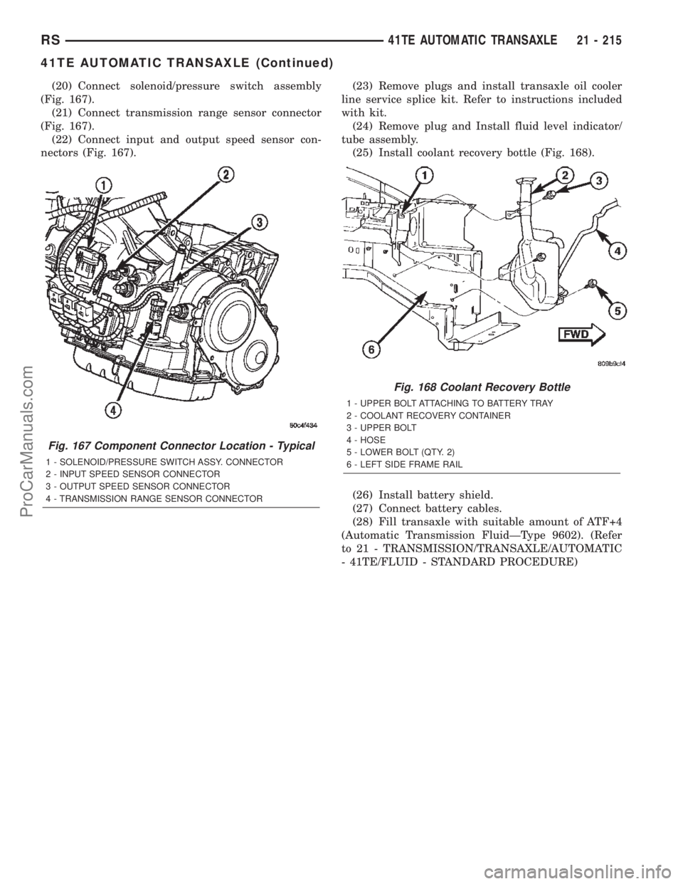
(20) Connect solenoid/pressure switch assembly
(Fig. 167).
(21) Connect transmission range sensor connector
(Fig. 167).
(22) Connect input and output speed sensor con-
nectors (Fig. 167).(23) Remove plugs and install transaxle oil cooler
line service splice kit. Refer to instructions included
with kit.
(24) Remove plug and Install fluid level indicator/
tube assembly.
(25) Install coolant recovery bottle (Fig. 168).
(26) Install battery shield.
(27) Connect battery cables.
(28) Fill transaxle with suitable amount of ATF+4
(Automatic Transmission FluidÐType 9602). (Refer
to 21 - TRANSMISSION/TRANSAXLE/AUTOMATIC
- 41TE/FLUID - STANDARD PROCEDURE)
Fig. 167 Component Connector Location - Typical
1 - SOLENOID/PRESSURE SWITCH ASSY. CONNECTOR
2 - INPUT SPEED SENSOR CONNECTOR
3 - OUTPUT SPEED SENSOR CONNECTOR
4 - TRANSMISSION RANGE SENSOR CONNECTOR
Fig. 168 Coolant Recovery Bottle
1 - UPPER BOLT ATTACHING TO BATTERY TRAY
2 - COOLANT RECOVERY CONTAINER
3 - UPPER BOLT
4 - HOSE
5 - LOWER BOLT (QTY. 2)
6 - LEFT SIDE FRAME RAIL
RS41TE AUTOMATIC TRANSAXLE21 - 215
41TE AUTOMATIC TRANSAXLE (Continued)
ProCarManuals.com