2002 CHRYSLER VOYAGER Interior
[x] Cancel search: InteriorPage 2291 of 2399
(2) Remove the instrument panel from the vehicle.
(Refer to 23 - BODY/INSTRUMENT PANEL/IN-
STRUMENT PANEL ASSEMBLY - REMOVAL).
(3) Place the instrument panel face down on a
suitable work surface. Be certain to take the proper
precautions to protect the face of the instrument
panel from cosmetic damage.
(4) Remove the fasteners that secure the demister
ducts to the instrument panel armature.
(5) Disengage the demister ducts from the demis-
ter outlets.
(6) Remove the demister ducts from the instru-
ment panel.
INSTALLATION
WARNING: ON VEHICLES EQUIPPED WITH AIR-
BAGS, DISABLE THE AIRBAG SYSTEM BEFORE
ATTEMPTING ANY STEERING WHEEL, STEERING
COLUMN, OR INSTRUMENT PANEL COMPONENT
DIAGNOSIS OR SERVICE. DISCONNECT AND ISO-
LATE THE BATTERY NEGATIVE (GROUND) CABLE,
THEN WAIT TWO MINUTES FOR THE AIRBAG SYS-
TEM CAPACITOR TO DISCHARGE BEFORE PER-
FORMING FURTHER DIAGNOSIS OR SERVICE. THIS
IS THE ONLY SURE WAY TO DISABLE THE AIRBAG
SYSTEM. FAILURE TO TAKE THE PROPER PRE-
CAUTIONS COULD RESULT IN ACCIDENTAL AIR-
BAG DEPLOYMENT AND POSSIBLE PERSONAL
INJURY.
(1) Position the demister ducts to the instrument
panel.
(2) Engage the demister ducts to the demister out-
lets.
(3) Install the fasteners that secure the demister
ducts to the instrument panel armature.
(4) Reinstall the instrument panel into the vehicle.
(Refer to 23 - BODY/INSTRUMENT PANEL/IN-
STRUMENT PANEL ASSEMBLY - INSTALLA-
TION).
(5) Reconnect the battery negative cable.
FLOOR DISTRIBUTION DUCTS
REMOVAL
(1) Roll back the carpet on the front floor from
under the instrument panel toward the rear of the
vehicle. (Refer to 23 - BODY/INTERIOR/CARPETS
AND FLOOR MATS - REMOVAL).
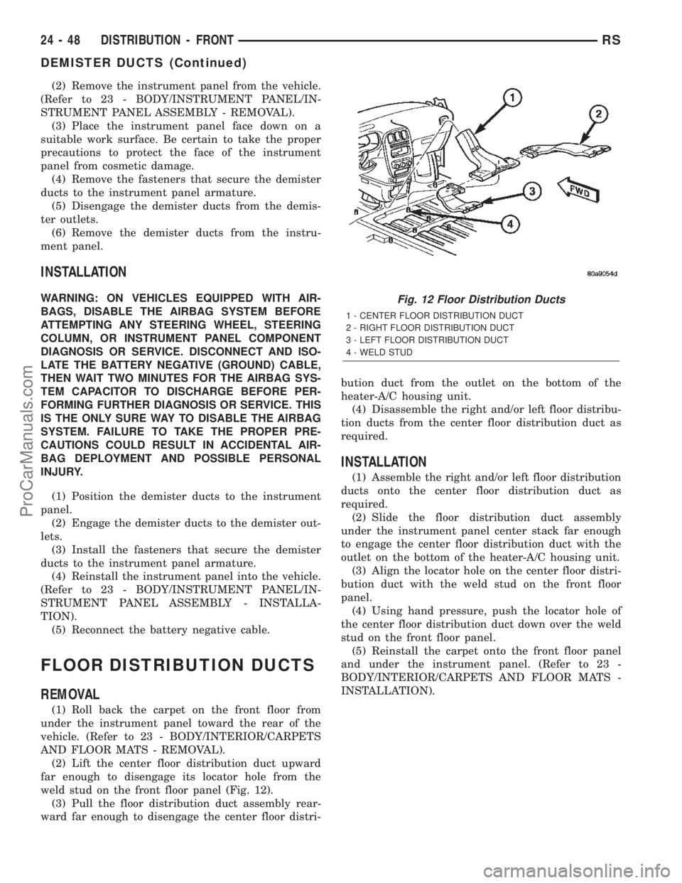
(2) Lift the center floor distribution duct upward
far enough to disengage its locator hole from the
weld stud on the front floor panel (Fig. 12).
(3) Pull the floor distribution duct assembly rear-
ward far enough to disengage the center floor distri-bution duct from the outlet on the bottom of the
heater-A/C housing unit.
(4) Disassemble the right and/or left floor distribu-
tion ducts from the center floor distribution duct as
required.
INSTALLATION
(1) Assemble the right and/or left floor distribution
ducts onto the center floor distribution duct as
required.
(2) Slide the floor distribution duct assembly
under the instrument panel center stack far enough
to engage the center floor distribution duct with the
outlet on the bottom of the heater-A/C housing unit.
(3) Align the locator hole on the center floor distri-
bution duct with the weld stud on the front floor
panel.
(4) Using hand pressure, push the locator hole of
the center floor distribution duct down over the weld
stud on the front floor panel.
(5) Reinstall the carpet onto the front floor panel
and under the instrument panel. (Refer to 23 -
BODY/INTERIOR/CARPETS AND FLOOR MATS -
INSTALLATION).
Fig. 12 Floor Distribution Ducts
1 - CENTER FLOOR DISTRIBUTION DUCT
2 - RIGHT FLOOR DISTRIBUTION DUCT
3 - LEFT FLOOR DISTRIBUTION DUCT
4 - WELD STUD
24 - 48 DISTRIBUTION - FRONTRS
DEMISTER DUCTS (Continued)
ProCarManuals.com
Page 2294 of 2399
DISTRIBUTION - REAR
TABLE OF CONTENTS
page page
AIR OUTLETS
DESCRIPTION.........................51
REMOVAL.............................51
INSTALLATION.........................51
A/C DISTRIBUTION DUCT
REMOVAL.............................52
INSTALLATION.........................52
BLOWER MOTOR
DESCRIPTION.........................52
OPERATION...........................52DIAGNOSIS AND TESTING - BLOWER
MOTOR .............................53
REMOVAL.............................53
INSTALLATION.........................55
REAR HEATER-A/C HOUSING
REMOVAL.............................55
INSTALLATION.........................56
REAR HEATER DISTRIBUTION DUCT
REMOVAL.............................58
INSTALLATION.........................58
AIR OUTLETS
DESCRIPTION
Based upon the system mode selected, conditioned
air can exit the rear heater-A/C unit housing through
one or a combination of the two main housing out-
lets: air conditioner, or heater. Once the conditioned
air exits the unit housing, it is directed through
molded plastic ducts to the various outlets in the
vehicle interior. These outlets and their locations are
as follows:
²Floor Outlets- Three floor outlets with fixed
vanes are located in the right quarter trim panel,
near the floor. These outlets distribute air from the
rear heater distribution duct to the intermediate and
rear seat occupants. The floor outlets are integral to
the right quarter trim panel and, if faulty or dam-
aged, the quarter trim panel must be replaced.
²Overhead Outlets- Four (two right side and
two left side) fully adjustable outlets along the roof
rails distribute air from the rear A/C distribution
duct and the headliner ducts to the intermediate and
rear seat occupants. The headliner ducts are integral
to the headliner panel. Each overhead outlet is
housed in a headliner bezel. The two forward head-
liner bezels also feature a courtesy lamp, a fold-away
coat hook, and a fold-away assist handle. The over-
head outlets can be removed from the headliner
bezels individually for service replacement.
REMOVAL
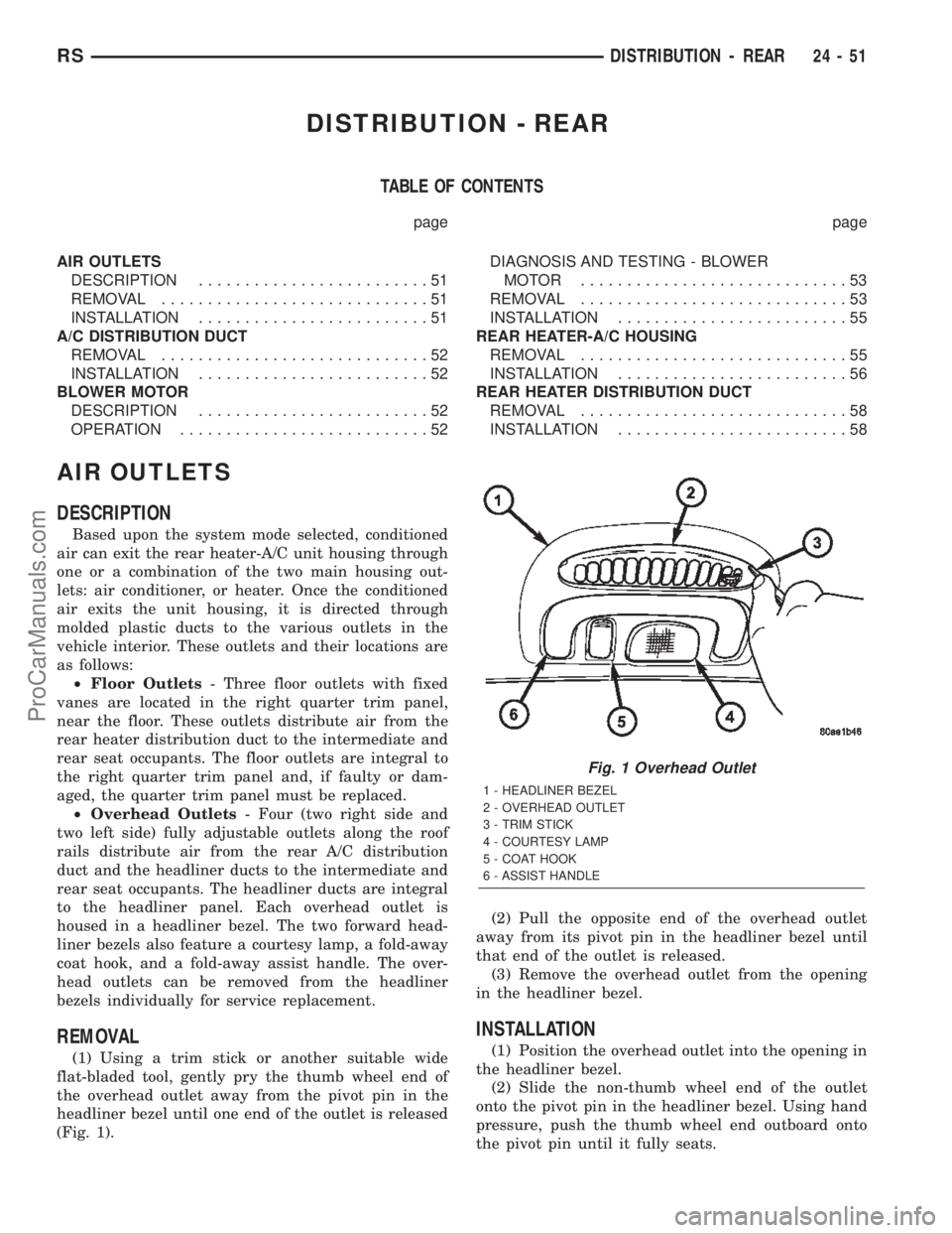
(1) Using a trim stick or another suitable wide
flat-bladed tool, gently pry the thumb wheel end of
the overhead outlet away from the pivot pin in the
headliner bezel until one end of the outlet is released
(Fig. 1).(2) Pull the opposite end of the overhead outlet
away from its pivot pin in the headliner bezel until
that end of the outlet is released.
(3) Remove the overhead outlet from the opening
in the headliner bezel.
INSTALLATION
(1) Position the overhead outlet into the opening in
the headliner bezel.
(2) Slide the non-thumb wheel end of the outlet
onto the pivot pin in the headliner bezel. Using hand
pressure, push the thumb wheel end outboard onto
the pivot pin until it fully seats.
Fig. 1 Overhead Outlet
1 - HEADLINER BEZEL
2 - OVERHEAD OUTLET
3 - TRIM STICK
4 - COURTESY LAMP
5 - COAT HOOK
6 - ASSIST HANDLE
RSDISTRIBUTION - REAR24-51
ProCarManuals.com
Page 2299 of 2399
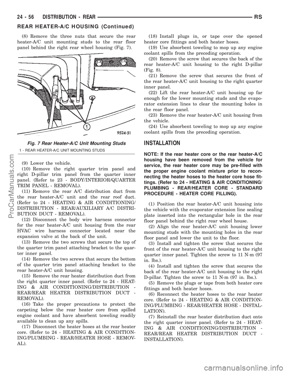
(8) Remove the three nuts that secure the rear
heater-A/C unit mounting studs to the rear floor
panel behind the right rear wheel housing (Fig. 7).
(9) Lower the vehicle.
(10) Remove the right quarter trim panel and
right D-pillar trim panel from the quarter inner
panel. (Refer to 23 - BODY/INTERIOR/QUARTER
TRIM PANEL - REMOVAL).
(11) Remove the rear A/C distribution duct from
the rear heater-A/C unit and the rear roof duct.
(Refer to 24 - HEATING & AIR CONDITIONING/
DISTRIBUTION - REAR/AUXILIARY A/C DISTRI-
BUTION DUCT - REMOVAL).
(12) Disconnect the body wire harness connector
for the rear heater-A/C unit housing from the rear
HVAC wire harness connector located near the
expansion valve at the back of the unit.
(13) Remove the two screws that secure the top of
the quarter trim panel attaching bracket to the quar-
ter inner panel.
(14) Remove the two screws that secure the bottom
of the quarter trim panel attaching bracket to the
rear heater-A/C unit housing.
(15) Remove the rear heater distribution duct from
the right quarter inner panel. (Refer to 24 - HEAT-
ING & AIR CONDITIONING/DISTRIBUTION -
REAR/REAR HEATER DISTRIBUTION DUCT -
REMOVAL).
(16) Take the proper precautions to protect the
carpeting below the rear heater core from spilled
engine coolant and have absorbent toweling readily
available to clean up any spills.
(17) Disconnect the heater hoses at the rear heater
core. (Refer to 24 - HEATING & AIR CONDITION-
ING/PLUMBING - REAR/HEATER HOSE - REMOV-
AL).(18) Install plugs in, or tape over the opened
heater core fittings and both heater hoses.
(19) Use absorbent toweling to mop up any engine
coolant spills from the preceding operation.
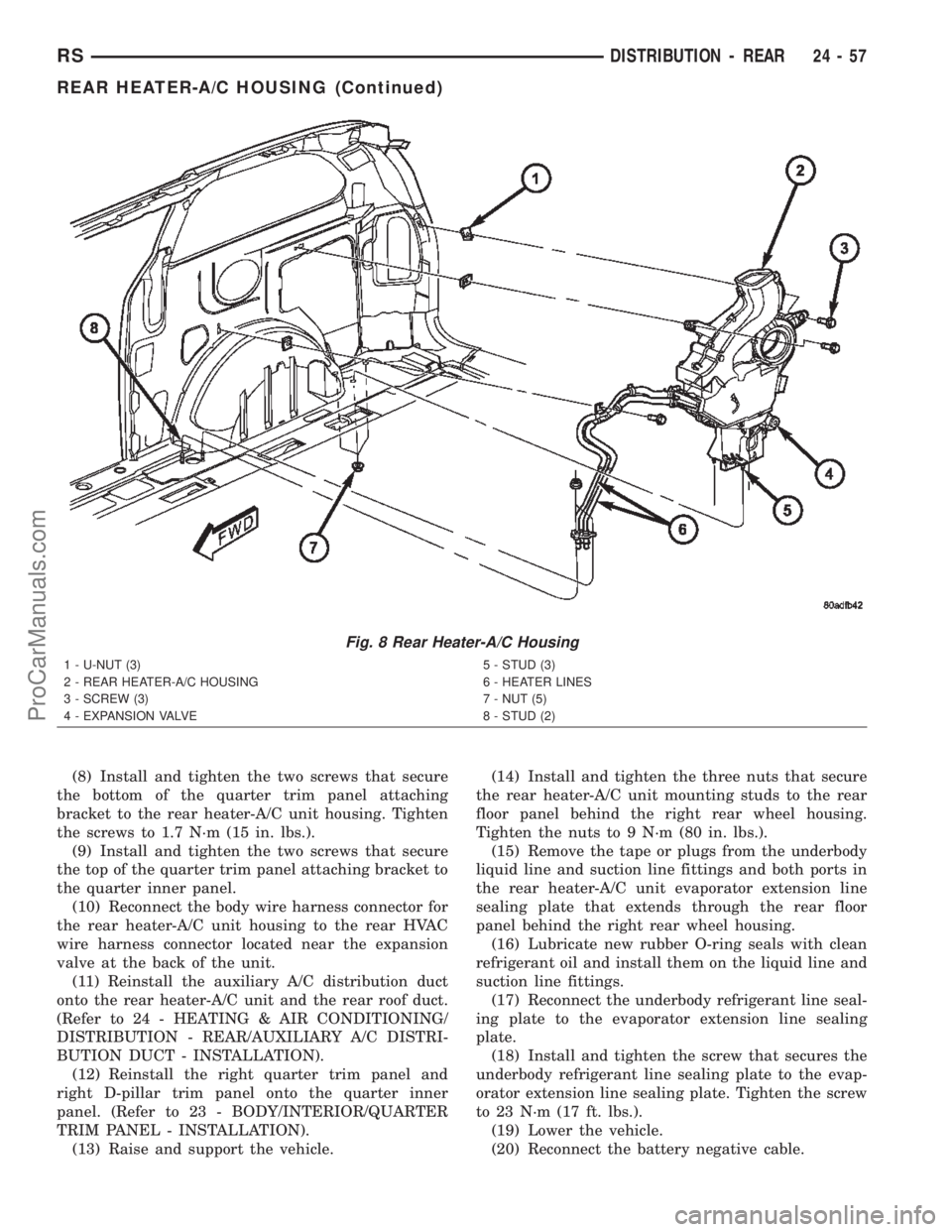
(20) Remove the screw that secures the back of the
rear heater-A/C unit housing to the right D-pillar
(Fig. 8).
(21) Remove the screw that secures the front of
the rear heater-A/C unit housing to the right quarter
inner panel.
(22) Lift the rear heater-A/C unit housing up far
enough for the lower mounting studs and the evapo-
rator extension lines to clear the mounting holes in
the rear floor panel.
(23) Remove the rear heater-A/C unit housing from
the vehicle.
(24) Use absorbent toweling to mop up any engine
coolant spills from the preceding operation.
INSTALLATION
NOTE: If the rear heater core or the rear heater-A/C
housing have been removed from the vehicle for
service, the rear heater core may be pre-filled with
the proper engine coolant mixture prior to recon-
necting the heater hoses to the heater core hose fit-
tings. (Refer to 24 - HEATING & AIR CONDITIONING/
PLUMBING - REAR/HEATER CORE - STANDARD
PROCEDURE - HEATER CORE FILLING).
(1) Position the rear heater-A/C unit housing into
the vehicle with the evaporator extension line sealing
plate inserted into the rectangular hole in the rear
floor panel behind the right rear wheel house.
(2) Align the rear heater-A/C unit housing lower
mounting studs with the mounting holes in the rear
floor panel and lower the unit to the floor.
(3) Install and tighten the screw that secures the
front of the rear heater-A/C unit housing to the right
quarter inner panel. Tighten the screw to 11 N´m (97
in. lbs.).
(4) Install and tighten the screw that secures the
back of the rear heater-A/C unit housing to the right
D-pillar. Tighten the screw to 11 N´m (97 in. lbs.).
(5) Remove the plugs or tape from both heater core
fittings and both heater hoses.
(6) Reconnect the heater hoses to the rear heater
core. (Refer to 24 - HEATING & AIR CONDITION-
ING/PLUMBING - REAR/HEATER HOSE - INSTAL-
LATION).
(7) Reinstall the rear heater distribution duct onto
the right quarter inner panel. (Refer to 24 - HEAT-
ING & AIR CONDITIONING/DISTRIBUTION -
REAR/REAR HEATER DISTRIBUTION DUCT -
INSTALLATION).
Fig. 7 Rear Heater-A/C Unit Mounting Studs
1 - REAR HEATER-A/C UNIT MOUNTING STUDS
24 - 56 DISTRIBUTION - REARRS
REAR HEATER-A/C HOUSING (Continued)
ProCarManuals.com
Page 2300 of 2399
(8) Install and tighten the two screws that secure
the bottom of the quarter trim panel attaching
bracket to the rear heater-A/C unit housing. Tighten
the screws to 1.7 N´m (15 in. lbs.).
(9) Install and tighten the two screws that secure
the top of the quarter trim panel attaching bracket to
the quarter inner panel.
(10) Reconnect the body wire harness connector for
the rear heater-A/C unit housing to the rear HVAC
wire harness connector located near the expansion
valve at the back of the unit.
(11) Reinstall the auxiliary A/C distribution duct
onto the rear heater-A/C unit and the rear roof duct.
(Refer to 24 - HEATING & AIR CONDITIONING/
DISTRIBUTION - REAR/AUXILIARY A/C DISTRI-
BUTION DUCT - INSTALLATION).
(12) Reinstall the right quarter trim panel and
right D-pillar trim panel onto the quarter inner
panel. (Refer to 23 - BODY/INTERIOR/QUARTER
TRIM PANEL - INSTALLATION).
(13) Raise and support the vehicle.(14) Install and tighten the three nuts that secure
the rear heater-A/C unit mounting studs to the rear
floor panel behind the right rear wheel housing.
Tighten the nuts to 9 N´m (80 in. lbs.).
(15) Remove the tape or plugs from the underbody
liquid line and suction line fittings and both ports in
the rear heater-A/C unit evaporator extension line
sealing plate that extends through the rear floor
panel behind the right rear wheel housing.
(16) Lubricate new rubber O-ring seals with clean
refrigerant oil and install them on the liquid line and
suction line fittings.
(17) Reconnect the underbody refrigerant line seal-
ing plate to the evaporator extension line sealing
plate.
(18) Install and tighten the screw that secures the
underbody refrigerant line sealing plate to the evap-
orator extension line sealing plate. Tighten the screw
to 23 N´m (17 ft. lbs.).
(19) Lower the vehicle.
(20) Reconnect the battery negative cable.
Fig. 8 Rear Heater-A/C Housing
1 - U-NUT (3)
2 - REAR HEATER-A/C HOUSING
3 - SCREW (3)
4 - EXPANSION VALVE5 - STUD (3)
6 - HEATER LINES
7 - NUT (5)
8 - STUD (2)
RSDISTRIBUTION - REAR24-57
REAR HEATER-A/C HOUSING (Continued)
ProCarManuals.com
Page 2301 of 2399
(21) Refill the engine cooling system. (Refer to 7 -
COOLING - STANDARD PROCEDURE - COOLING
SYSTEM REFILL).
(22) Evacuate the refrigerant system. (Refer to 24
- HEATING & AIR CONDITIONING/PLUMBING -
FRONT/REFRIGERANT - STANDARD PROCE-
DURE - REFRIGERANT SYSTEM EVACUATE).
(23) Charge the refrigerant system. (Refer to 24 -
HEATING & AIR CONDITIONING/PLUMBING -
FRONT/REFRIGERANT - STANDARD PROCE-
DURE - REFRIGERANT SYSTEM CHARGE).
(24) Run the HVAC Cooldown test to verify proper
operation(Refer to 24 - HEATING & AIR CONDI-
TIONING - DIAGNOSIS AND TESTING).
REAR HEATER DISTRIBUTION
DUCT
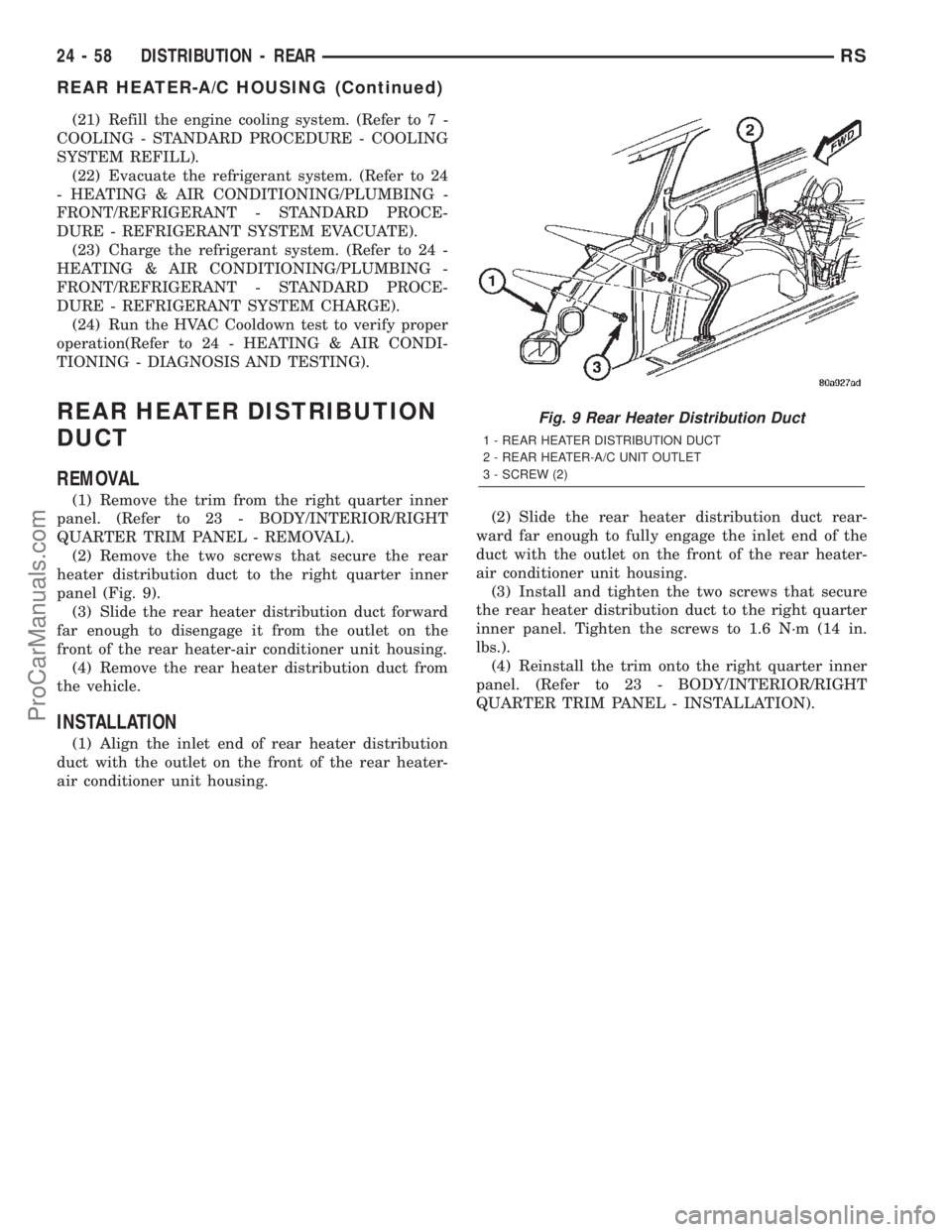
REMOVAL
(1) Remove the trim from the right quarter inner
panel. (Refer to 23 - BODY/INTERIOR/RIGHT
QUARTER TRIM PANEL - REMOVAL).
(2) Remove the two screws that secure the rear
heater distribution duct to the right quarter inner
panel (Fig. 9).
(3) Slide the rear heater distribution duct forward
far enough to disengage it from the outlet on the
front of the rear heater-air conditioner unit housing.
(4) Remove the rear heater distribution duct from
the vehicle.
INSTALLATION
(1) Align the inlet end of rear heater distribution
duct with the outlet on the front of the rear heater-
air conditioner unit housing.(2) Slide the rear heater distribution duct rear-
ward far enough to fully engage the inlet end of the
duct with the outlet on the front of the rear heater-
air conditioner unit housing.
(3) Install and tighten the two screws that secure
the rear heater distribution duct to the right quarter
inner panel. Tighten the screws to 1.6 N´m (14 in.
lbs.).
(4) Reinstall the trim onto the right quarter inner
panel. (Refer to 23 - BODY/INTERIOR/RIGHT
QUARTER TRIM PANEL - INSTALLATION).
Fig. 9 Rear Heater Distribution Duct
1 - REAR HEATER DISTRIBUTION DUCT
2 - REAR HEATER-A/C UNIT OUTLET
3 - SCREW (2)
24 - 58 DISTRIBUTION - REARRS
REAR HEATER-A/C HOUSING (Continued)
ProCarManuals.com
Page 2345 of 2399
(4) Carefully pour the proper pre-mixed engine
coolant solution into the rear heater core through a
funnel until coolant begins to appear at the lower
hose fitting of the heater core.
(5) Use absorbent toweling to clean up any engine
coolant spills from the preceding operation.
(6) Reconnect the heater hoses to the rear heater
core. (Refer to 24 - HEATING & AIR CONDITION-
ING/PLUMBING - REAR/HEATER HOSE - INSTAL-
LATION).
(7) Refill the engine cooling system. (Refer to 7 -
COOLING - STANDARD PROCEDURE - COOLING
SYSTEM REFILL).
THERMAL CYCLING
If the rear heater core was emptied and was not
pre-filled, it will be necessary to thermal cycle the
vehicle at least two times to ensure that the rear
heater core is properly filled.
(1) Refill the engine cooling system. (Refer to 7 -
COOLING - STANDARD PROCEDURE - COOLING
SYSTEM REFILL).
(2) Start the engine and allow it to operate until
the thermostat opens.
(3) Turn the engine off and allow it to cool.
(4) With the engine cold and not running, check
and top off the engine coolant level as necessary.
(Refer to 7 - COOLING - STANDARD PROCEDURE
- COOLANT LEVEL CHECK) and (Refer to 7 -
COOLING - STANDARD PROCEDURE - COOLANT
- ADDING).
(5) Start the engine and allow it to operate until
the thermostat opens again.
(6) Turn the engine off and allow it to cool down
again.
(7) With the engine cold and not running, check
and top off the engine coolant level as necessary.
(Refer to 7 - COOLING - STANDARD PROCEDURE
- COOLANT LEVEL CHECK) and (Refer to 7 -
COOLING - STANDARD PROCEDURE - COOLANT
- ADDING).
(8) Check the performance of the rear heater.
Refer to REAR HEATER PERFORMANCE CHECK .
REAR HEATER PERFORMANCE CHECK
Successful completion of the rear heater perfor-
mance check will confirm that the rear heater core is
properly filled with engine coolant. If the check is not
successful, either there is still air trapped in the rear
heater core or the rear heater plumbing is restricted.
This check should be performed with the vehicle in a
shop where the ambient temperature is about 21É C
(70É F).
(1) Start the engine and allow it to idle until it
warms up to normal operating temperature.(2) Adjust the heater-A/C controls so that the front
heater is turned Off, the rear heater is set for full
Heat, and the rear blower motor is at its highest
speed setting.
(3) Use an accurate test thermometer to measure
the temperature of the air being discharged from the
rear heater outlet located at the base of the right
C-pillar.
(4) Proper discharge air temperature readings
should be from 57É to 63É C (135É to 145É F).
REMOVAL
WARNING: REFER TO THE APPLICABLE WARN-
INGS AND CAUTIONS FOR THIS SYSTEM BEFORE
PERFORMING THE FOLLOWING OPERATION.
(Refer to 24 - HEATING & AIR CONDITIONING/
PLUMBING FRONT - WARNING - HEATER PLUMB-
ING).
(1) Drain the engine cooling system. (Refer to 7 -
COOLING - STANDARD PROCEDURE - COOLING
SYSTEM DRAIN).
(2) Remove the right quarter trim panel and right
D-pillar trim panel from the quarter inner panel.
(Refer to 23 - BODY/INTERIOR/QUARTER TRIM
PANEL - REMOVAL).
(3) Remove the rear heater distribution duct from
the right quarter inner panel. (Refer to 24 - HEAT-
ING & AIR CONDITIONING/DISTRIBUTION -
REAR/REAR HEATER DISTRIBUTION DUCT -
REMOVAL).
(4) Remove the screw that secures the back of the
rear heater-A/C unit housing to the right D-pillar.
(5) Remove the screw that secures the front of the
rear heater-A/C unit housing to the right quarter
inner panel.
(6) Take the proper precautions to protect the car-
peting below the rear heater core from spilled engine
coolant and have absorbent toweling readily avail-
able to mop up any spills.
(7) Disconnect the heater hoses at the rear heater
core. (Refer to 24 - HEATING & AIR CONDITION-
ING/PLUMBING - REAR/HEATER HOSE - REMOV-
AL).
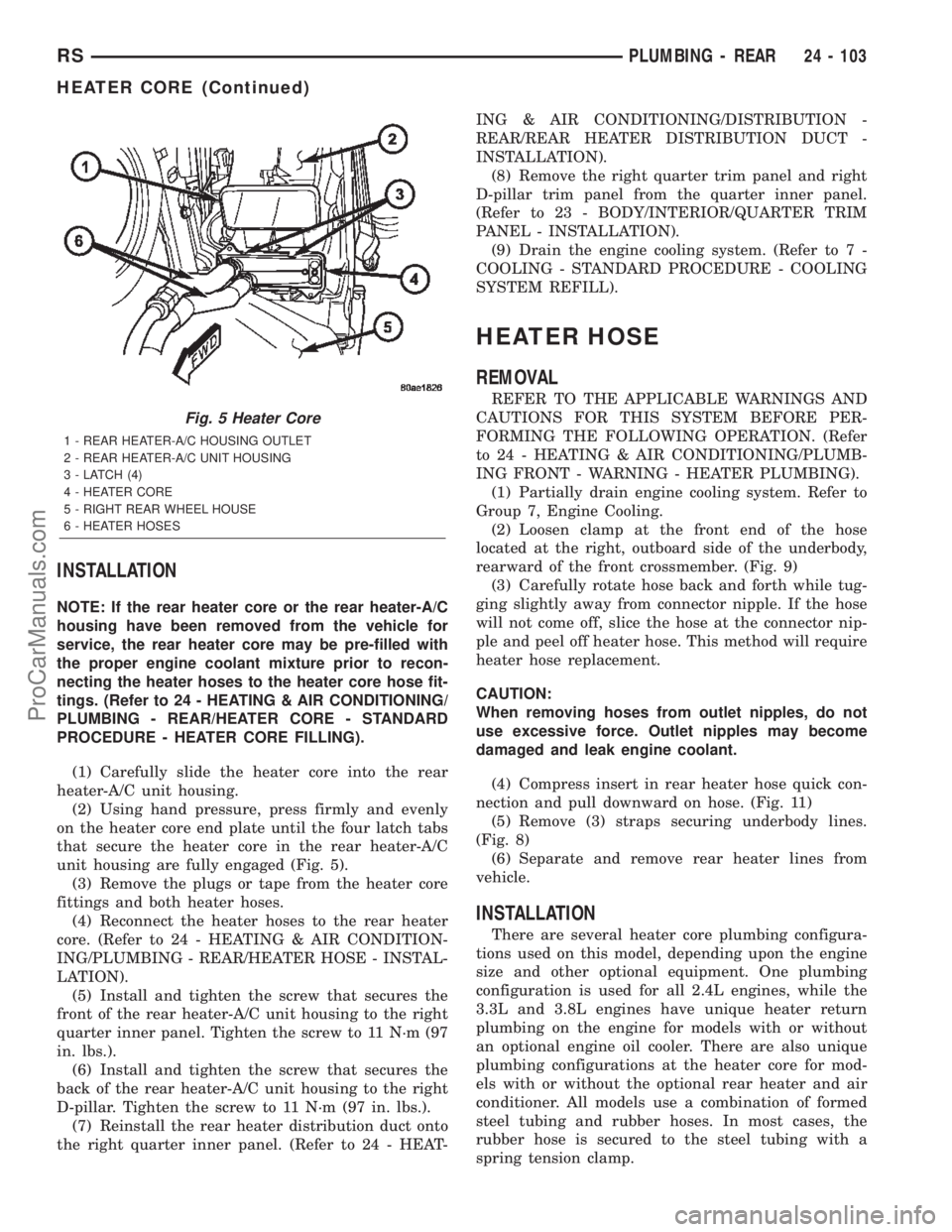
(8) Install plugs in, or tape over the opened heater
core fittings and both heater hoses (Fig. 5).
(9) Use absorbent toweling to clean up any engine
coolant spills from the preceding operation.
(10) Release the four latch tabs that secure the
heater core in the rear heater-A/C unit housing.
(11) Carefully pull the heater core straight out of
the rear heater-A/C unit housing.
(12) Use absorbent toweling to clean up any
engine coolant spills from the preceding operation.
24 - 102 PLUMBING - REARRS
HEATER CORE (Continued)
ProCarManuals.com
Page 2346 of 2399
INSTALLATION
NOTE: If the rear heater core or the rear heater-A/C
housing have been removed from the vehicle for
service, the rear heater core may be pre-filled with
the proper engine coolant mixture prior to recon-
necting the heater hoses to the heater core hose fit-
tings. (Refer to 24 - HEATING & AIR CONDITIONING/
PLUMBING - REAR/HEATER CORE - STANDARD
PROCEDURE - HEATER CORE FILLING).
(1) Carefully slide the heater core into the rear
heater-A/C unit housing.
(2) Using hand pressure, press firmly and evenly
on the heater core end plate until the four latch tabs
that secure the heater core in the rear heater-A/C
unit housing are fully engaged (Fig. 5).
(3) Remove the plugs or tape from the heater core
fittings and both heater hoses.
(4) Reconnect the heater hoses to the rear heater
core. (Refer to 24 - HEATING & AIR CONDITION-
ING/PLUMBING - REAR/HEATER HOSE - INSTAL-
LATION).
(5) Install and tighten the screw that secures the
front of the rear heater-A/C unit housing to the right
quarter inner panel. Tighten the screw to 11 N´m (97
in. lbs.).
(6) Install and tighten the screw that secures the
back of the rear heater-A/C unit housing to the right
D-pillar. Tighten the screw to 11 N´m (97 in. lbs.).
(7) Reinstall the rear heater distribution duct onto
the right quarter inner panel. (Refer to 24 - HEAT-ING & AIR CONDITIONING/DISTRIBUTION -
REAR/REAR HEATER DISTRIBUTION DUCT -
INSTALLATION).
(8) Remove the right quarter trim panel and right
D-pillar trim panel from the quarter inner panel.
(Refer to 23 - BODY/INTERIOR/QUARTER TRIM
PANEL - INSTALLATION).
(9) Drain the engine cooling system. (Refer to 7 -
COOLING - STANDARD PROCEDURE - COOLING
SYSTEM REFILL).
HEATER HOSE
REMOVAL
REFER TO THE APPLICABLE WARNINGS AND
CAUTIONS FOR THIS SYSTEM BEFORE PER-
FORMING THE FOLLOWING OPERATION. (Refer
to 24 - HEATING & AIR CONDITIONING/PLUMB-
ING FRONT - WARNING - HEATER PLUMBING).
(1) Partially drain engine cooling system. Refer to
Group 7, Engine Cooling.
(2) Loosen clamp at the front end of the hose
located at the right, outboard side of the underbody,
rearward of the front crossmember. (Fig. 9)
(3) Carefully rotate hose back and forth while tug-
ging slightly away from connector nipple. If the hose
will not come off, slice the hose at the connector nip-
ple and peel off heater hose. This method will require
heater hose replacement.
CAUTION:
When removing hoses from outlet nipples, do not
use excessive force. Outlet nipples may become
damaged and leak engine coolant.
(4) Compress insert in rear heater hose quick con-
nection and pull downward on hose. (Fig. 11)
(5) Remove (3) straps securing underbody lines.
(Fig. 8)
(6) Separate and remove rear heater lines from
vehicle.
INSTALLATION
There are several heater core plumbing configura-
tions used on this model, depending upon the engine
size and other optional equipment. One plumbing
configuration is used for all 2.4L engines, while the
3.3L and 3.8L engines have unique heater return
plumbing on the engine for models with or without
an optional engine oil cooler. There are also unique
plumbing configurations at the heater core for mod-
els with or without the optional rear heater and air
conditioner. All models use a combination of formed
steel tubing and rubber hoses. In most cases, the
rubber hose is secured to the steel tubing with a
spring tension clamp.
Fig. 5 Heater Core
1 - REAR HEATER-A/C HOUSING OUTLET
2 - REAR HEATER-A/C UNIT HOUSING
3 - LATCH (4)
4 - HEATER CORE
5 - RIGHT REAR WHEEL HOUSE
6 - HEATER HOSES
RSPLUMBING - REAR24 - 103
HEATER CORE (Continued)
ProCarManuals.com