2002 CHRYSLER VOYAGER Interior
[x] Cancel search: InteriorPage 2064 of 2399
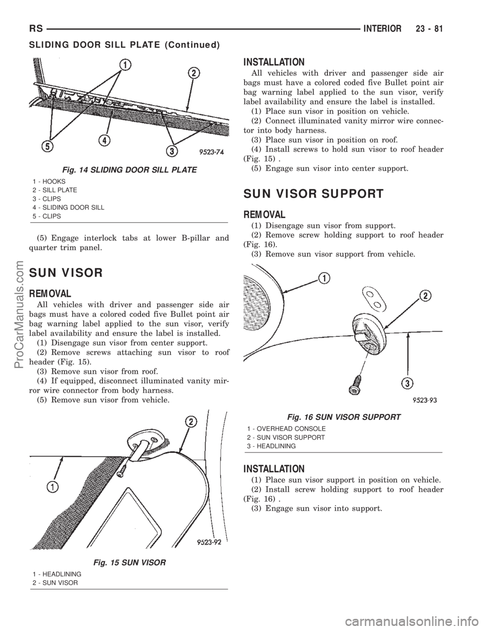
(5) Engage interlock tabs at lower B-pillar and
quarter trim panel.
SUN VISOR
REMOVAL
All vehicles with driver and passenger side air
bags must have a colored coded five Bullet point air
bag warning label applied to the sun visor, verify
label availability and ensure the label is installed.
(1) Disengage sun visor from center support.
(2) Remove screws attaching sun visor to roof
header (Fig. 15).
(3) Remove sun visor from roof.
(4) If equipped, disconnect illuminated vanity mir-
ror wire connector from body harness.
(5) Remove sun visor from vehicle.
INSTALLATION
All vehicles with driver and passenger side air
bags must have a colored coded five Bullet point air
bag warning label applied to the sun visor, verify
label availability and ensure the label is installed.
(1) Place sun visor in position on vehicle.
(2) Connect illuminated vanity mirror wire connec-
tor into body harness.
(3) Place sun visor in position on roof.
(4) Install screws to hold sun visor to roof header
(Fig. 15) .
(5) Engage sun visor into center support.
SUN VISOR SUPPORT
REMOVAL
(1) Disengage sun visor from support.
(2) Remove screw holding support to roof header
(Fig. 16).
(3) Remove sun visor support from vehicle.
INSTALLATION
(1) Place sun visor support in position on vehicle.
(2) Install screw holding support to roof header
(Fig. 16) .
(3) Engage sun visor into support.
Fig. 14 SLIDING DOOR SILL PLATE
1 - HOOKS
2 - SILL PLATE
3 - CLIPS
4 - SLIDING DOOR SILL
5 - CLIPS
Fig. 15 SUN VISOR
1 - HEADLINING
2 - SUN VISOR
Fig. 16 SUN VISOR SUPPORT
1 - OVERHEAD CONSOLE
2 - SUN VISOR SUPPORT
3 - HEADLINING
RSINTERIOR23-81
SLIDING DOOR SILL PLATE (Continued)
ProCarManuals.com
Page 2065 of 2399
FLOOR CONSOLE TRAY
REMOVAL
(1) Remove the floor console. Refer to the Owner's
Manual for proper procedures.
(2) Remove the four screws and remove the tray.
INSTALLATION
(1) Install the floor console tray and install the
screws.
(2) Install the floor console. Refer to the Owner's
Manual for proper procedures.
FLOOR CONSOLE TRAY -
BRACKET ASSEMBLY
REMOVAL
(1) Remove the floor carpet. (Refer to 23 - BODY/
INTERIOR/CARPETS AND FLOOR MATS -
REMOVAL)
(2) Disconnect the electrical connector.
(3) Remove the four screws and remove the
bracket assembly.
INSTALLATION
(1) Install the bracket assembly and install the
four screws.
(2) Connect the electrical connector.
(3) Install the floor carpet. (Refer to 23 - BODY/
INTERIOR/CARPETS AND FLOOR MATS -
INSTALLATION)
23 - 82 INTERIORRS
ProCarManuals.com
Page 2066 of 2399
PAINT
TABLE OF CONTENTS
page page
PAINT
SPECIFICATIONS - COLOR CODE CHARTS . . 83
BASE COAT/CLEARCOAT FINISH
DESCRIPTION.........................83
PAINT CODE
DESCRIPTION.........................84PAINTED TOUCH-UP
DESCRIPTION.........................84
FINESSE SANDING/BUFFING & POLISHING
DESCRIPTION.........................84
PAINT
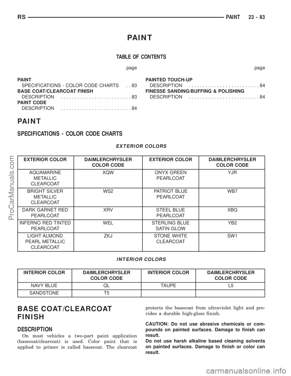
SPECIFICATIONS - COLOR CODE CHARTS
EXTERIOR COLORS
EXTERIOR COLOR DAIMLERCHRYSLER
COLOR CODEEXTERIOR COLOR DAIMLERCHRYSLER
COLOR CODE
AQUAMARINE
METALLIC
CLEARCOATXQW ONYX GREEN
PEARLCOATYJR
BRIGHT SILVER
METALLIC
CLEARCOATWS2 PATRIOT BLUE
PEARLCOATWB7
DARK GARNET RED
PEARLCOATXRV STEEL BLUE
PEARLCOATXBQ
INFERNO RED TINTED
PEARLCOATWEL STERLING BLUE
SATIN GLOWYB2
LIGHT ALMOND
PEARL METALLIC
CLEARCOATZKJ STONE WHITE
CLEARCOATSW1
INTERIOR COLORS
INTERIOR COLOR DAIMLERCHRYSLER
COLOR CODEINTERIOR COLOR DAIMLERCHRYSLER
COLOR CODE
NAVY BLUE QL TAUPE L5
SANDSTONE T5
BASE COAT/CLEARCOAT
FINISH
DESCRIPTION
On most vehicles a two-part paint application
(basecoat/clearcoat) is used. Color paint that is
applied to primer is called basecoat. The clearcoatprotects the basecoat from ultraviolet light and pro-
vides a durable high-gloss finish.
CAUTION: Do not use abrasive chemicals or com-
pounds on painted surfaces. Damage to finish can
result.
Do not use harsh alkaline based cleaning solvents
on painted surfaces. Damage to finish or color can
result.
RSPAINT23-83
ProCarManuals.com
Page 2090 of 2399
STATIONARY GLASS
TABLE OF CONTENTS
page page
WINDSHIELD
DESCRIPTION........................107
WARNING
WINDSHIELD SAFETY PRECAUTIONS....107
REMOVAL............................107
INSTALLATION........................108
SLIDING DOOR GLASS
REMOVAL............................109INSTALLATION........................109
QUARTER WINDOW
REMOVAL............................110
INSTALLATION........................110
REAR DOOR GLASS
REMOVAL............................110
INSTALLATION........................110
WINDSHIELD
DESCRIPTION
The windshield is attached to the window frame
with urethane adhesive. The urethane adhesive is
applied cold and seals the surface area between the
window opening and the glass. The primer adheres
the urethane adhesive to the windshield.
It is difficult to salvage a windshield during the
removal operation. The windshield is part of the
structural support for the roof. The urethane bonding
used to secure the windshield to the fence is difficult
to cut or clean from any surface. If the moldings are
set in urethane, it would also be unlikely they could
be salvaged. Before removing the windshield, check
the availability of the windshield and moldings from
the parts supplier.
WARNING
WINDSHIELD SAFETY PRECAUTIONS
WARNING: DO NOT OPERATE THE VEHICLE
WITHIN 24 HOURS OF WINDSHIELD INSTALLATION.
IT TAKES AT LEAST 24 HOURS FOR URETHANE
ADHESIVE TO CURE. IF IT IS NOT CURED, THE
WINDSHIELD MAY NOT PERFORM PROPERLY IN
AN ACCIDENT.
URETHANE ADHESIVES ARE APPLIED AS A SYS-
TEM. USE GLASS CLEANER, GLASS PREP SOL-
VENT, GLASS PRIMER, PVC (VINYL) PRIMER AND
PINCH WELD (FENCE) PRIMER PROVIDED BY THE
ADHESIVE MANUFACTURER. IF NOT, STRUCTURAL
INTEGRITY COULD BE COMPROMISED.
DAIMLERCHRYSLER DOES NOT RECOMMEND
GLASS ADHESIVE BY BRAND. TECHNICIANS
SHOULD REVIEW PRODUCT LABELS AND TECHNI-
CAL DATA SHEETS, AND USE ONLY ADHESIVESTHAT THEIR MANUFACTURES WARRANT WILL
RESTORE A VEHICLE TO THE REQUIREMENTS OF
FMVSS 212. TECHNICIANS SHOULD ALSO INSURE
THAT PRIMERS AND CLEANERS ARE COMPATIBLE
WITH THE PARTICULAR ADHESIVE USED.
BE SURE TO REFER TO THE URETHANE MANU-
FACTURER'S DIRECTIONS FOR CURING TIME
SPECIFICATIONS, AND DO NOT USE ADHESIVE
AFTER ITS EXPIRATION DATE.
VAPORS THAT ARE EMITTED FROM THE URE-
THANE ADHESIVE OR PRIMER COULD CAUSE
PERSONAL INJURY. USE THEM IN A WELL-VENTI-
LATED AREA.
SKIN CONTACT WITH URETHANE ADHESIVE
SHOULD BE AVOIDED. PERSONAL INJURY MAY
RESULT.
ALWAYS WEAR EYE AND HAND PROTECTION
WHEN WORKING WITH GLASS.
CAUTION: Protect all painted and trimmed surfaces
from coming in contact with urethane or primers.
Be careful not to damage painted surfaces when
removing moldings or cutting urethane around
windshield.
REMOVAL
WINDSHIELD REMOVAL ± EXTERIOR METHOD
The urethane adhesive holding the windshield to
the opening pinch weld (fence) can be cut using a
sharp cold knife from the exterior of the vehicle.
Using the cold knife method is effective if the wind-
shield is already broken. If the glass must be sal-
vaged, cutting the urethane adhesive from the
interior of the vehicle using a reciprocating or oscil-
lating power knife is recommended.
(1) Remove inside rear view mirror.
(2) Remove windshield wiper arms.
(3) Remove cowl cover.
RSSTATIONARY GLASS23 - 107
ProCarManuals.com
Page 2091 of 2399

(4) Remove A-pillar trim panels.
(5) Disconnect wire connectors to windshield
defroster grid.
(6) Place protective covers over instrument panel
and hood.
(7) Remove windshield molding. Using pliers, pull
outward on molding at the bottom of A-pillars.
(8) Using a sharp cold knife, cut urethane adhe-
sive holding the windshield to the A-pillars, roof
header and cowl pinch weld fences (Fig. 1). A power
cutting device can be used if available.
(9) Remove windshield from vehicle.
WINDSHIELD REMOVAL ± INTERIOR METHOD
(1) Remove inside rear view mirror.
(2) Remove instrument panel top cover. Refer to
Group 8E, Instrument Panel and Systems.
(3) Remove A-pillar trim covers.
(4) Disconnect wire connectors to windshield
defroster grid.
(5) Place protective covers over instrument panel
and hood.
(6) Using a reciprocating or oscillating power
knife, cut urethane adhesive holding the windshield
to the A-pillars, roof header and cowl pinch weld
fences. Refer to instructions provided with the equip-
ment being used.
(7) Remove windshield from vehicle.
INSTALLATION
The urethane adhesive holding the windshield to
the opening pinch weld (fence) can be cut using a
sharp cold knife from the exterior of the vehicle.
Using the cold knife method is effective if the wind-
shield is already broken. If the glass must be sal-
vaged, cutting the urethane adhesive from the
interior of the vehicle using a reciprocating or oscil-
lating power knife is recommended.
CAUTION: Open the left front door glass before
installing windshield to avoid pressurizing the pas-senger compartment. If a door is slammed before
urethane bonding is cured, water leaks can result.
Allow the urethane at least 24 hours to cure before
returning the vehicle to use.
To avoid stressing the replacement windshield, the
urethane bonding material on the windshield fence
should be smooth and consistent to the shape of
the replacement windshield . The support spacers
should be cleaned and properly installed on weld
studs or repair screws at bottom of windshield
opening.
(1) Place replacement windshield into windshield
opening and position glass in the center of the open-
ing against the compression spacers.
(2) Verify the glass lays evenly against the pinch
weld fence at the sides, top and bottom of the
replacement windshield. If not, the pinch weld fence
must be formed to the shape of the new glass.
(3) Remove replacement windshield from wind-
shield opening.
(4) Position the windshield inside up on a suitable
work surface with two padded, wood 10 cm by 10 cm
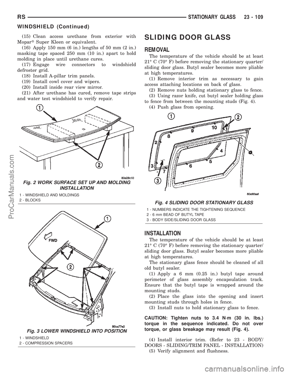
by 50 cm (4 in. by 4 in. by 20 in.) blocks, placed par-
allel 75 cm (2.5 ft.) apart (Fig. 2).
WARNING: DO NOT USE SOLVENT BASED GLASS
CLEANER TO CLEAN WINDSHIELD BEFORE
APPLYING GLASS PREP AND PRIMER. POOR
ADHESION CAN RESULT.
(5) Clean inside of windshield with ammonia based
glass cleaner and lint-free cloth.
(6) Install molding to perimeter of windshield.
(7) Apply Glass Prep adhesion promoter 25 mm (1
in.) wide around perimeter of windshield and wipe
with clean/dry lint-free cloth until no streaks are vis-
ible.
(8) Apply Glass Primer 25 mm (1 in.) wide around
perimeter of windshield. Allow at least three minutes
drying time.
(9) Using a razor knife, remove as much original
urethane as possible. Do not damage paint on wind-
shield fence.
(10) Apply pinch weld primer 19 mm (0.75 in.)
wide around the windshield fence. Allow at least
three minutes drying time.
(11) If a low viscosity urethane adhesive is used,
install compression spacers on the fence around the
windshield opening (Fig. 3).
(12) Apply a 10 mm (0.4 in.) bead of urethane on
center line of windshield fence.
(13) With the aid of a helper, position the wind-
shield over the windshield opening.
(14) Slowly lower windshield glass to windshield
opening fence. Guide the molding into proper position
as necessary. Push windshield inward until molding
is flush to roof line and A-pillars (Fig. 3).
Fig. 1 CUT URETHANE AROUND WINDSHIELD
1 - COLD KNIFE
2 - WINDSHIELD
23 - 108 STATIONARY GLASSRS
WINDSHIELD (Continued)
ProCarManuals.com
Page 2092 of 2399
(15) Clean access urethane from exterior with
MopartSuper Kleen or equivalent.
(16) Apply 150 mm (6 in.) lengths of 50 mm (2 in.)
masking tape spaced 250 mm (10 in.) apart to hold
molding in place until urethane cures.
(17) Engage wire connectors to windshield
defroster grid.
(18) Install A-pillar trim panels.
(19) Install cowl cover and wipers.
(20) Install inside rear view mirror.
(21) After urethane has cured, remove tape strips
and water test windshield to verify repair.SLIDING DOOR GLASS
REMOVAL
The temperature of the vehicle should be at least
21É C (70É F) before removing the stationary quarter/
sliding door glass. Butyl sealer becomes more pliable
at high temperatures.
(1) Remove interior trim as necessary to gain
access attaching locations on back of glass.
(2) Remove nuts holding stationary glass to fence.
(3)
Using razor knife, cut butyl sealer holding glass
to fence from between the mounting studs (Fig. 4).
(4) Push glass from opening.
INSTALLATION
The temperature of the vehicle should be at least
21É C (70É F) before removing the stationary quarter/
sliding door glass. Butyl sealer becomes more pliable
at high temperatures.
The stationary glass fence should be cleaned of all
old butyl sealer.
(1) Applya6mm(0.25 in.) butyl tape around
perimeter of glass assembly encapsulation track.
Ensure that the butyl tape is wrapped around the
mounting studs.
(2) Place the glass into the opening and insert
mounting studs through holes in fence.
(3) Install nuts to hold stationary glass to fence.
CAUTION: Tighten nuts to 3.4 N´m (30 in. lbs.)
torque in the sequence indicated. Do not over
torque, or glass breakage may result (Fig. 4).
(4) Install interior trim. (Refer to 23 - BODY/
DOORS - SLIDING/TRIM PANEL - INSTALLATION)
(5) Verify alignment and flushness.
Fig. 2 WORK SURFACE SET UP AND MOLDING
INSTALLATION
1 - WINDSHIELD AND MOLDINGS
2 - BLOCKS
Fig. 3 LOWER WINDSHIELD INTO POSITION
1 - WINDSHIELD
2 - COMPRESSION SPACERS
Fig. 4 SLIDING DOOR STATIONARY GLASS
1 - NUMBERS INDICATE THE TIGHTENING SEQUENCE
2-6mmBEAD OF BUTYL TAPE
3 - BODY SIDE/SLIDING DOOR GLASS
RSSTATIONARY GLASS23 - 109
WINDSHIELD (Continued)
ProCarManuals.com
Page 2093 of 2399
QUARTER WINDOW
REMOVAL
(1) Remove C-pillar trim.
(2) Open quarter glass to vent position.
(3) Disengage quarter window retainer from vent
motor arm.
(4) Remove nuts attaching quarter glass to C-pillar
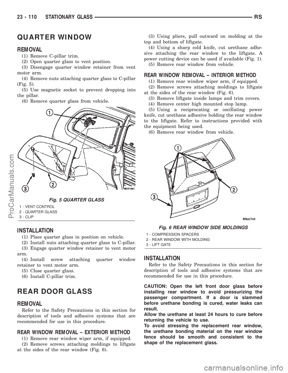
(Fig. 5).
(5) Use magnetic socket to prevent dropping into
the pillar.
(6) Remove quarter glass from vehicle.
INSTALLATION
(1) Place quarter glass in position on vehicle.
(2) Install nuts attaching quarter glass to C-pillar.
(3) Engage quarter window retainer to vent motor
arm.
(4) Install screw attaching quarter window
retainer to vent motor arm.
(5) Close quarter glass.
(6) Install C-pillar trim.
REAR DOOR GLASS
REMOVAL
Refer to the Safety Precautions in this section for
description of tools and adhesive systems that are
recommended for use in this procedure.
REAR WINDOW REMOVAL ± EXTERIOR METHOD
(1) Remove rear window wiper arm, if equipped.
(2) Remove screws attaching moldings to liftgate
at the sides of the rear window (Fig. 6).(3) Using pliers, pull outward on molding at the
top and bottom of liftgate.
(4) Using a sharp cold knife, cut urethane adhe-
sive attaching the rear window to the liftgate. A
power cutting device can be used if available (Fig. 1).
(5) Remove rear window from vehicle.
REAR WINDOW REMOVAL ± INTERIOR METHOD
(1) Remove rear window wiper arm, if equipped.
(2) Remove screws attaching moldings to liftgate
at the sides of the rear window (Fig. 6).
(3) Remove liftgate inside lamps and trim covers.
(4) Remove center high mounted stop lamp.
(5) Using a reciprocating or oscillating power
knife, cut urethane adhesive holding the rear window
to the liftgate. Refer to instructions provided with
the equipment being used.
(6) Remove rear window from vehicle.
INSTALLATION
Refer to the Safety Precautions in this section for
description of tools and adhesive systems that are
recommended for use in this procedure.
CAUTION: Open the left front door glass before
installing rear window to avoid pressurizing the
passenger compartment. If a door is slammed
before urethane bonding is cured, water leaks can
result.
Allow the urethane at least 24 hours to cure before
returning the vehicle to use.
To avoid stressing the replacement rear window,
the urethane bonding material on the rear window
fence should be smooth and consistent to the
shape of the replacement glass.
Fig. 5 QUARTER GLASS
1 - VENT CONTROL
2 - QUARTER GLASS
3 - CLIP
Fig. 6 REAR WINDOW SIDE MOLDINGS
1 - COMPRESSION SPACERS
2 - REAR WINDOW WITH MOLDING
3 - LIFT GATE
23 - 110 STATIONARY GLASSRS
ProCarManuals.com
Page 2094 of 2399

(1) Place replacement glass into rear window open-
ing.
(2) Verify the glass lays evenly against the pinch
weld fence at the sides, top and bottom of the
replacement rear window. If not, the fence must be
formed to the shape of the new glass.
(3) Using a grease pencil, mark the glass and lift-
gate in several locations to aid installation.
(4) Remove replacement glass from liftgate open-
ing.
(5) Position the rear window inside up on a suit-
able work surface with two padded, wood 10 cm by
10 cm by 50 cm (4 in. by 4 in. by 20 in.) blocks,
placed parallel 75 cm (2.5 ft.) apart (Fig. 2).
WARNING: DO NOT USE SOLVENT BASED GLASS
CLEANER TO CLEAN REAR WINDOW BEFORE
APPLYING GLASS PREP AND PRIMER. POOR
ADHESION CAN RESULT.
(6) Clean inside of rear window with ammonia
based glass cleaner and lint-free cloth.
(7) Apply molding to top and bottom of rear win-
dow.
(8) Apply Glass Prep adhesion promoter 25 mm (1
in.) wide around perimeter of rear window and wipe
with clean/dry lint-free cloth until no streaks are vis-
ible.
(9) Apply Glass Primer 25 mm (1 in.) wide around
perimeter of rear window. Allow at least three min-
utes drying time.
(10) Apply Pinch weld Primer 19 mm (0.75 in.)
wide around the rear window fence. Allow at least
three minutes drying time.
(11) If a low viscosity urethane adhesive is used,
install compression spacers on the fence around the
rear window opening (Fig. 7).(12) Apply a 10 mm (0.4 in.) bead of urethane
along center line of rear window fence.
(13) With the aid of a helper, position the rear
window over the rear window opening and align the
reference marks.
(14) Slowly lower the glass to rear window opening
fence. Guide the molding into proper position as nec-
essary. Push glass inward until molding is flush to
liftgate surface (Fig. 7).
(15) Clean excess urethane from exterior with
MopartSuper Kleen, or equivalent.
(16) Apply 150 mm (6 in.) lengths of 50 mm (2 in.)
masking tape spaced 250 mm (10 in.) apart to hold
molding in place until urethane cures.
(17) Install rear window side moldings and wiper
arm (Fig. 6).
(18) Install interior trim.
(19) After urethane has cured, remove tape strips
and water test rear window to verify repair.
Fig. 7 LOWER REAR WINDOW INTO POSITION
1 - REAR WINDOW WITH MOLDING
2 - LIFTGATE
RSSTATIONARY GLASS23 - 111
REAR DOOR GLASS (Continued)
ProCarManuals.com