2002 CHRYSLER VOYAGER Interior
[x] Cancel search: InteriorPage 2246 of 2399
pressed, the set temp value will become 55 but the
display will show LO. If the set temp is 85 and the
up button is pressed, the set temp value will become
90 but the display will show HIGH. Temperatures
can be displayed in either metric or Fahrenheit,
which is controlled from the overhead console.
²A rocker switch that selects a cool-down rate.
LO-AUTO or HI-AUTO are displayed when the sys-
tem is in automatic operation.
²A defroster button which turns on the defroster
independently during full automatic control. A
defroster symbol illuminates in the display when the
button is pressed.
²Air recirculation button. A Recirculation symbol
appears in the display when the button is pressed, or
when the system exceeds 80 percent circulated air
under automatic control due to high air conditioning
demand.
²Rear window defogger on/off switch. A graphic
symbol shows when the defroster is on.
²An air conditioning button that allows the com-
pressor to be turned off. A Snowflake symbol is illu-
minated when air conditioning is on, whether under
manual or automatic control.
²Rotary knob for front fan speed selection can
override the automatic controls. LEDs surrounding
the knob show the current setting.
²Rotary knob for control of the Rear system.
²A rotary knob for mode control can override the
automatic controls. LEDs surrounding the knob show
the current setting.
²Computer logic remembers the settings of the
controls when the ignition is turned off and retains
those settings after a restart. If the system is off
when the ignition is turned off it will be off when the
engine is restarted, etc.
²Computer logic provides variable air recircula-
tion under high temperature and humidity condi-
tions. Because recirculation is generally accompanied
by increased fan noise, the proportion of recirculated
to outside air gradually approaches full recirculation
over a broad temperature range.
²A graphic symbol of the windshield that illumi-
nates when the windshield wiper deicer is active.
REAR CONTROL PANEL
A rear control panel centrally mounted on the
headliner includes a vacuum-flourescent digital dis-
play, a rocker control for temperature and rotary con-
trols for adjustment of mode and fan speed control of
the rear unit by intermediate seat passengers.
OPERATION
OPERATION - DUAL ZONE
²The mode control knob enables continously vari-
able proportioning of air flow between modes but has
detents adjacent to each icon.
²The blower control provides five separate speeds.
²When the fan is off, the HVAC computer closes
the recirculation door to prevent outside air from
entering the passenger compartment.
²Interior air may be recirculated to speed up
heating or cooling in all modes except defrost and
mix by pressing the Recirculate button on the control
panel.
²To reduce humidity for rapid defogging the A/C
compressor runs automatically in modes from ªmix'
to full defrost when outside temperatures are above
freezing.
²Air conditioning is available in any mode by
pressing the snowflake, A/C on/off, button.
OPERATION - MANUAL THREE ZONE
FRONT CONTROL PANEL
²Primary control of the rear compartment unit is
on the instrument panel. This control allows the
driver to set the rear compartment fan speed, to turn
the rear unit off, or to give control to the intermedi-
ate seat occupants by switching to the REAR posi-
tion. When the rear unit is controlled from the
instrument panel, rear air temperature is based on
the driver-side temperature control position, and the
mode (floor or overhead air) is based on the front
control's mode position.
²The mode control knob enables continously vari-
able proportioning of air flow between modes but has
detents adjacent to each icon.
²The blower control provides five separate speeds
and Off. When the fan is off, the HVAC computer
closes the recirculation door to prevent outside air
from entering the passenger compartment.
²Interior air may be recirculated to speed up
heating or cooling in all modes exccept defrost and
mix by pressing the Recirculate button on the control
panel.
²To reduce humidity for rapid defogging the A/C
compressor runs automatically in modes from ªmix'
to full defrost when outside temperatures are above
freezing.
²Air conditioning is available in any mode by
pressing the snowflake, A/C on/off, button.
RSHEATING & AIR CONDITIONING24-3
HEATING & AIR CONDITIONING (Continued)
ProCarManuals.com
Page 2274 of 2399
high and the other connection low, the blend air door
will move in one direction. When the module reverses
the polarity of the voltage to the motor, the blend air
door moves in the opposite direction. When the mod-
ule makes the voltage to both connections high or
both connections low, the blend air door stops and
will not move. These same motor connections also
provide a feedback signal to the front heater-A/C con-
trol module. This feedback signal allows the module
to monitor the operation and relative positions of the
blend door actuator and the blend air door. The front
heater-A/C control module learns the blend air door
stop positions during the calibration procedure and
will store a Diagnostic Trouble Code (DTC) for any
problems it detects in the blend door actuator cir-
cuits. A DTC can be retrieved and the blend door
actuator can be diagnosed using a DRBIIItscan tool.
Refer to the appropriate diagnostic information.
REMOVAL
(1) Disconnect and isolate the battery negative
cable.
(2) Remove the right quarter trim panel and right
D-pillar trim panel from the quarter inner panel.
(Refer to 23 - BODY/INTERIOR/QUARTER TRIM
PANEL - REMOVAL).
(3) Remove the two screws that secure the top of
the quarter trim panel attaching bracket to the quar-
ter inner panel.
(4) Remove the screw that secures the back of the
rear heater-A/C unit housing to the right D-pillar.
(5) Remove the screw that secures the front of the
rear heater-A/C unit housing to the right quarter
inner panel.
(6) Carefully pull the top of the rear heater-A/C
unit housing away from the right quarter inner panel
far enough to reach between the rear heater-A/C unit
housing and the quarter inner panel to access the
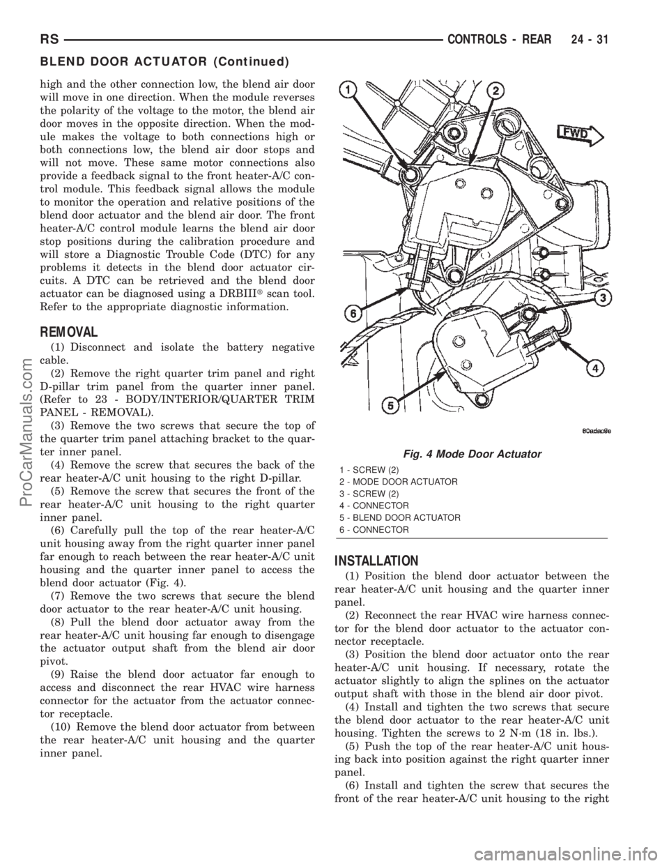
blend door actuator (Fig. 4).
(7) Remove the two screws that secure the blend
door actuator to the rear heater-A/C unit housing.
(8) Pull the blend door actuator away from the
rear heater-A/C unit housing far enough to disengage
the actuator output shaft from the blend air door
pivot.
(9) Raise the blend door actuator far enough to
access and disconnect the rear HVAC wire harness
connector for the actuator from the actuator connec-
tor receptacle.
(10) Remove the blend door actuator from between
the rear heater-A/C unit housing and the quarter
inner panel.
INSTALLATION
(1) Position the blend door actuator between the
rear heater-A/C unit housing and the quarter inner
panel.
(2) Reconnect the rear HVAC wire harness connec-
tor for the blend door actuator to the actuator con-
nector receptacle.
(3) Position the blend door actuator onto the rear
heater-A/C unit housing. If necessary, rotate the
actuator slightly to align the splines on the actuator
output shaft with those in the blend air door pivot.
(4) Install and tighten the two screws that secure
the blend door actuator to the rear heater-A/C unit
housing. Tighten the screws to 2 N´m (18 in. lbs.).
(5) Push the top of the rear heater-A/C unit hous-
ing back into position against the right quarter inner
panel.
(6) Install and tighten the screw that secures the
front of the rear heater-A/C unit housing to the right
Fig. 4 Mode Door Actuator
1 - SCREW (2)
2 - MODE DOOR ACTUATOR
3 - SCREW (2)
4 - CONNECTOR
5 - BLEND DOOR ACTUATOR
6 - CONNECTOR
RSCONTROLS - REAR24-31
BLEND DOOR ACTUATOR (Continued)
ProCarManuals.com
Page 2275 of 2399
quarter inner panel. Tighten the screw to 11 N´m (97
in. lbs.).
(7) Install and tighten the screw that secures the
back of the rear heater-A/C unit housing to the right
D-pillar. Tighten the screw to 11 N´m (97 in. lbs.).
(8) Install and tighten the two screws that secure
the top of the quarter trim panel attaching bracket to
the quarter inner panel. Tighten the screws to 1.7
N´m (15 in. lbs.).
(9) Reinstall the right quarter trim panel and
right D-pillar trim panel onto the quarter inner
panel. (Refer to 23 - BODY/INTERIOR/QUARTER
TRIM PANEL - INSTALLATION).
(10) Reconnect the battery negative cable.
(11) Perform the heater-A/C control calibration
procedure. (Refer to 24 - HEATING & AIR CONDI-
TIONING/CONTROLS - FRONT/A/C-HEATER CON-
TROL - STANDARD PROCEDURE - HEATER-A/C
CONTROL CALIBRATION).
BLOWER MOTOR RELAY
DESCRIPTION
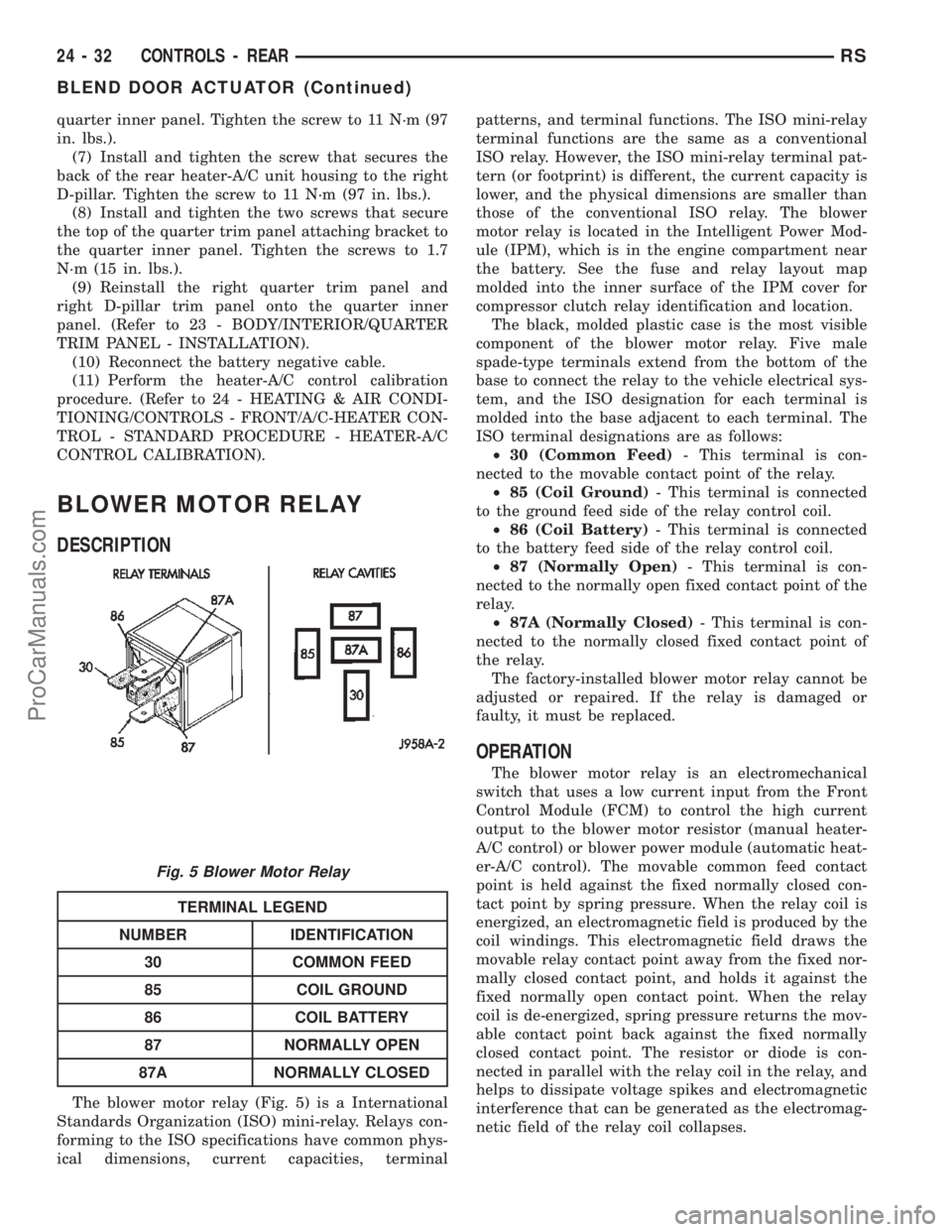
TERMINAL LEGEND
NUMBER IDENTIFICATION
30 COMMON FEED
85 COIL GROUND
86 COIL BATTERY
87 NORMALLY OPEN
87A NORMALLY CLOSED
The blower motor relay (Fig. 5) is a International
Standards Organization (ISO) mini-relay. Relays con-
forming to the ISO specifications have common phys-
ical dimensions, current capacities, terminalpatterns, and terminal functions. The ISO mini-relay
terminal functions are the same as a conventional
ISO relay. However, the ISO mini-relay terminal pat-
tern (or footprint) is different, the current capacity is
lower, and the physical dimensions are smaller than
those of the conventional ISO relay. The blower
motor relay is located in the Intelligent Power Mod-
ule (IPM), which is in the engine compartment near
the battery. See the fuse and relay layout map
molded into the inner surface of the IPM cover for
compressor clutch relay identification and location.
The black, molded plastic case is the most visible
component of the blower motor relay. Five male
spade-type terminals extend from the bottom of the
base to connect the relay to the vehicle electrical sys-
tem, and the ISO designation for each terminal is
molded into the base adjacent to each terminal. The
ISO terminal designations are as follows:
²30 (Common Feed)- This terminal is con-
nected to the movable contact point of the relay.
²85 (Coil Ground)- This terminal is connected
to the ground feed side of the relay control coil.
²86 (Coil Battery)- This terminal is connected
to the battery feed side of the relay control coil.
²87 (Normally Open)- This terminal is con-
nected to the normally open fixed contact point of the
relay.
²87A (Normally Closed)- This terminal is con-
nected to the normally closed fixed contact point of
the relay.
The factory-installed blower motor relay cannot be
adjusted or repaired. If the relay is damaged or
faulty, it must be replaced.
OPERATION
The blower motor relay is an electromechanical
switch that uses a low current input from the Front
Control Module (FCM) to control the high current
output to the blower motor resistor (manual heater-
A/C control) or blower power module (automatic heat-
er-A/C control). The movable common feed contact
point is held against the fixed normally closed con-
tact point by spring pressure. When the relay coil is
energized, an electromagnetic field is produced by the
coil windings. This electromagnetic field draws the
movable relay contact point away from the fixed nor-
mally closed contact point, and holds it against the
fixed normally open contact point. When the relay
coil is de-energized, spring pressure returns the mov-
able contact point back against the fixed normally
closed contact point. The resistor or diode is con-
nected in parallel with the relay coil in the relay, and
helps to dissipate voltage spikes and electromagnetic
interference that can be generated as the electromag-
netic field of the relay coil collapses.
Fig. 5 Blower Motor Relay
24 - 32 CONTROLS - REARRS
BLEND DOOR ACTUATOR (Continued)
ProCarManuals.com
Page 2278 of 2399
DIAGNOSIS AND TESTING - BLOWER MOTOR
RESISTOR
Refer to the appropriate wiring information. The
wiring information includes wiring diagrams, proper
wire and connector repair procedures, details of wire
harness routing and retention, connector pin-out
information and location views for the various wire
harness connectors, splices and grounds.
(1) Disconnect and isolate the battery negative
cable.
(2) Disconnect the rear HVAC wire harness con-
nector for the blower motor resistor from the resistor
connector receptacle.
(3) Check for continuity between each of the
blower motor switch input terminals of the blower
motor resistor and the resistor output terminal. In
each case there should be continuity. If OK, repair
the wire harness circuits between the blower motor
switch and the blower motor resistor or the blower
motor pigtail wires as required. If not OK, replace
the faulty blower motor resistor.
REMOVAL
WARNING: THE BLOWER MOTOR RESISTOR MAY
GET VERY HOT DURING NORMAL OPERATION. IF
THE BLOWER MOTOR WAS TURNED ON, WAIT
FIVE MINUTES TO ALLOW THE BLOWER MOTOR
RESISTOR TO COOL BEFORE PERFORMING DIAG-
NOSIS OR SERVICE. FAILURE TO TAKE THIS PRE-
CAUTION CAN RESULT IN PERSONAL INJURY.
CAUTION: Do not operate the blower motor with the
blower motor resistor removed from the circuit.
Failure to take this precaution can result in vehicle
damage.
(1) Disconnect and isolate the battery negative
cable.
(2) Remove the right quarter trim panel and right
D-pillar trim panel from the quarter inner panel.
(Refer to 23 - BODY/INTERIOR/QUARTER TRIM
PANEL - REMOVAL).
(3) Disconnect the rear HVAC wire harness con-
nector for the blower motor resistor from the resistor
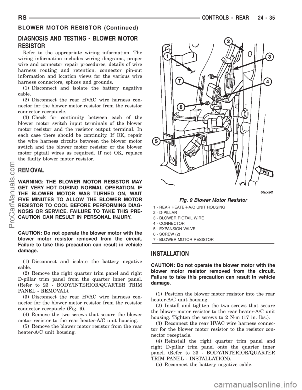
connector receptacle (Fig. 9).
(4) Remove the two screws that secure the blower
motor resistor to the rear heater-A/C unit housing.
(5) Remove the blower motor resistor from the rear
heater-A/C unit housing.
INSTALLATION
CAUTION: Do not operate the blower motor with the
blower motor resistor removed from the circuit.
Failure to take this precaution can result in vehicle
damage.
(1) Position the blower motor resistor into the rear
heater-A/C unit housing.
(2) Install and tighten the two screws that secure
the blower motor resistor to the rear heater-A/C unit
housing. Tighten the screws to 2 N´m (17 in. lbs.).
(3) Reconnect the rear HVAC wire harness connec-
tor for the blower motor resistor to the resistor con-
nector receptacle.
(4) Reinstall the right quarter trim panel and
right D-pillar trim panel onto the quarter inner
panel. (Refer to 23 - BODY/INTERIOR/QUARTER
TRIM PANEL - INSTALLATION).
(5) Reconnect the battery negative cable.
Fig. 9 Blower Motor Resistor
1 - REAR HEATER-A/C UNIT HOUSING
2 - D-PILLAR
3 - BLOWER PIGTAIL WIRE
4 - CONNECTOR
5 - EXPANSION VALVE
6 - SCREW (2)
7 - BLOWER MOTOR RESISTOR
RSCONTROLS - REAR24-35
BLOWER MOTOR RESISTOR (Continued)
ProCarManuals.com
Page 2279 of 2399
INFRARED TEMPERATURE
SENSOR
DESCRIPTION
The rear infrared temperature sensor consists of
an infrared transducer that is concealed behind the
lens of the rear heater-A/C control in the headliner.
This sensor is used only on models equipped with the
optional Automatic Temperature Control (ATC) heat-
ing and air conditioning system. The rear infrared
temperature sensor is integral to the rear heater-A/C
control. The infrared sensor cannot be adjusted or
repaired and, if faulty or damaged, the rear heater-
A/C control unit must be replaced.
OPERATION
The rear infrared temperature sensor provides an
independent measurement input to the Automatic
Temperature Control (ATC) heater-A/C control mod-
ule that indicates the surface temperature of the rear
seat occupants. By using a surface temperature mea-
surement, rather than an air temperature measure-
ment, the ATC system is able to adjust itself to the
comfort level as perceived by the occupant. This
allows the system to detect and compensate for other
ambient conditions affecting comfort levels, such as
solar heat gain or evaporative heat loss. The ATC
system logic responds to the infrared sensor input by
calculating and adjusting the air flow temperature
and air flow rate needed to properly obtain and
maintain the selected comfort level temperatures for
the rear seat occupants. The ATC heater-A/C control
module continually monitors the infrared sensor cir-
cuit, and will store a Diagnostic Trouble Code (DTC)
for any problem it detects. This DTC information can
be retrieved and the infrared temperature sensor
diagnosed using a DRBIIItscan tool. Refer to the
appropriate diagnostic information.
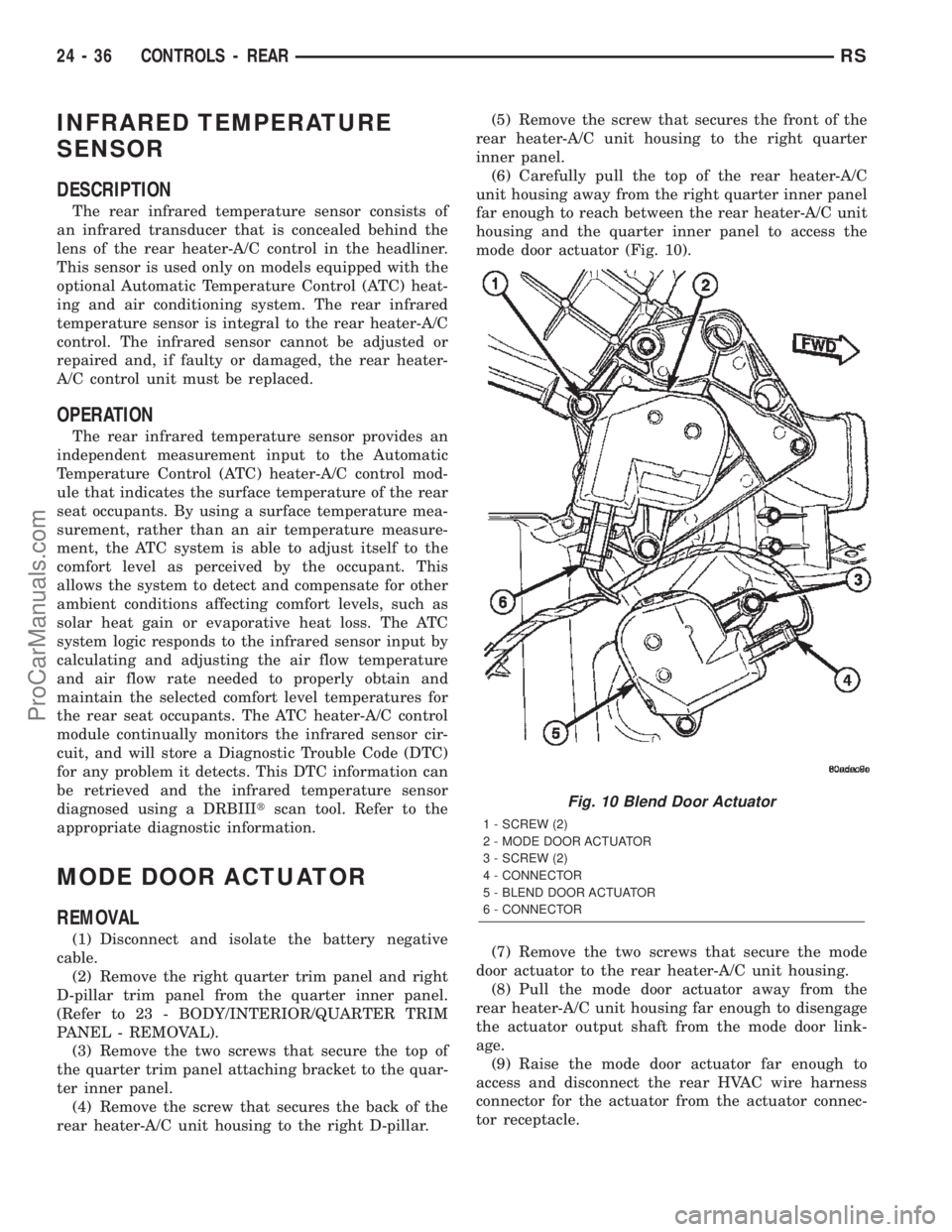
MODE DOOR ACTUATOR
REMOVAL
(1) Disconnect and isolate the battery negative
cable.
(2) Remove the right quarter trim panel and right
D-pillar trim panel from the quarter inner panel.
(Refer to 23 - BODY/INTERIOR/QUARTER TRIM
PANEL - REMOVAL).
(3) Remove the two screws that secure the top of
the quarter trim panel attaching bracket to the quar-
ter inner panel.
(4) Remove the screw that secures the back of the
rear heater-A/C unit housing to the right D-pillar.(5) Remove the screw that secures the front of the
rear heater-A/C unit housing to the right quarter
inner panel.
(6) Carefully pull the top of the rear heater-A/C
unit housing away from the right quarter inner panel
far enough to reach between the rear heater-A/C unit
housing and the quarter inner panel to access the
mode door actuator (Fig. 10).
(7) Remove the two screws that secure the mode
door actuator to the rear heater-A/C unit housing.
(8) Pull the mode door actuator away from the
rear heater-A/C unit housing far enough to disengage
the actuator output shaft from the mode door link-
age.
(9) Raise the mode door actuator far enough to
access and disconnect the rear HVAC wire harness
connector for the actuator from the actuator connec-
tor receptacle.
Fig. 10 Blend Door Actuator
1 - SCREW (2)
2 - MODE DOOR ACTUATOR
3 - SCREW (2)
4 - CONNECTOR
5 - BLEND DOOR ACTUATOR
6 - CONNECTOR
24 - 36 CONTROLS - REARRS
ProCarManuals.com
Page 2280 of 2399
(10) Remove the mode door actuator from between
the rear heater-A/C unit housing and the quarter
inner panel.
INSTALLATION
(1) Position the mode door actuator between the
rear heater-A/C unit housing and the quarter inner
panel.
(2) Reconnect the rear HVAC wire harness connec-
tor for the mode door actuator to the actuator connec-
tor receptacle.
(3) Position the mode door actuator onto the rear
heater-A/C unit housing. If necessary, rotate the
actuator slightly to align the splines on the actuator
output shaft with those in the mode door linkage.
(4) Install and tighten the two screws that secure
the mode door actuator to the rear heater-A/C unit
housing. Tighten the screws to 2 N´m (18 in. lbs.).
(5) Push the top of the rear heater-A/C unit hous-
ing back into position against the right quarter inner
panel.
(6) Install and tighten the screw that secures the
front of the rear heater-A/C unit housing to the right
quarter inner panel. Tighten the screw to 11 N´m (97
in. lbs.).
(7) Install and tighten the screw that secures the
back of the rear heater-A/C unit housing to the right
D-pillar. Tighten the screw to 11 N´m (97 in. lbs.).
(8) Install and tighten the two screws that secure
the top of the quarter trim panel attaching bracket to
the quarter inner panel. Tighten the screws to 1.7
N´m (15 in. lbs.).
(9) Reinstall the right quarter trim panel and
right D-pillar trim panel onto the quarter inner
panel. (Refer to 23 - BODY/INTERIOR/QUARTER
TRIM PANEL - INSTALLATION).
(10) Reconnect the battery negative cable.
(11) Perform the heater-A/C control calibration
procedure. (Refer to 24 - HEATING & AIR CONDI-
TIONING/CONTROLS - FRONT/A/C-HEATER CON-
TROL - STANDARD PROCEDURE - HEATER-A/C
CONTROL CALIBRATION).
POWER MODULE
DESCRIPTION
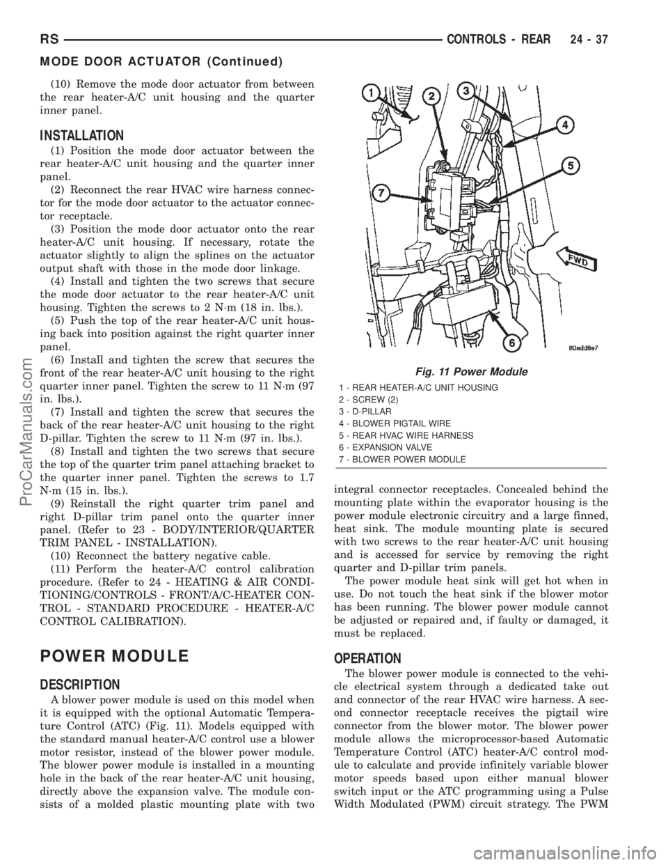
A blower power module is used on this model when
it is equipped with the optional Automatic Tempera-
ture Control (ATC) (Fig. 11). Models equipped with
the standard manual heater-A/C control use a blower
motor resistor, instead of the blower power module.
The blower power module is installed in a mounting
hole in the back of the rear heater-A/C unit housing,
directly above the expansion valve. The module con-
sists of a molded plastic mounting plate with twointegral connector receptacles. Concealed behind the
mounting plate within the evaporator housing is the
power module electronic circuitry and a large finned,
heat sink. The module mounting plate is secured
with two screws to the rear heater-A/C unit housing
and is accessed for service by removing the right
quarter and D-pillar trim panels.
The power module heat sink will get hot when in
use. Do not touch the heat sink if the blower motor
has been running. The blower power module cannot
be adjusted or repaired and, if faulty or damaged, it
must be replaced.
OPERATION
The blower power module is connected to the vehi-
cle electrical system through a dedicated take out
and connector of the rear HVAC wire harness. A sec-
ond connector receptacle receives the pigtail wire
connector from the blower motor. The blower power
module allows the microprocessor-based Automatic
Temperature Control (ATC) heater-A/C control mod-
ule to calculate and provide infinitely variable blower
motor speeds based upon either manual blower
switch input or the ATC programming using a Pulse
Width Modulated (PWM) circuit strategy. The PWM
Fig. 11 Power Module
1 - REAR HEATER-A/C UNIT HOUSING
2 - SCREW (2)
3 - D-PILLAR
4 - BLOWER PIGTAIL WIRE
5 - REAR HVAC WIRE HARNESS
6 - EXPANSION VALVE
7 - BLOWER POWER MODULE
RSCONTROLS - REAR24-37
MODE DOOR ACTUATOR (Continued)
ProCarManuals.com
Page 2281 of 2399

voltage is applied to a comparator circuit which com-
pares the PWM signal voltage to the blower motor
feedback voltage. The resulting output drives the
power module circuitry, which adjusts the voltage
output received from the blower motor relay to
change or maintain the desired blower speed. The
blower power module is diagnosed using a DRBIIIt
scan tool. Refer to the appropriate diagnostic infor-
mation.
REMOVAL
(1) Disconnect and isolate the battery negative
cable.
(2) Remove the right quarter trim panel and right
D-pillar trim panel from the quarter inner panel.
(Refer to 23 - BODY/INTERIOR/QUARTER TRIM
PANEL - REMOVAL).
(3) Disconnect the rear HVAC wire harness con-
nector for the blower power module from the resistor
connector receptacle (Fig. 12).
(4) Disconnect the blower motor pigtail wire con-
nector from the blower power module connector
receptacle.
(5) Remove the two screws that secure the blower
power module to the rear heater-A/C unit housing.
(6) Remove the blower power module from the rear
heater-A/C unit housing.
INSTALLATION
(1) Position the blower power module into the rear
heater-A/C unit housing.
(2) Install and tighten the two screws that secure
the blower power module to the rear heater-A/C unit
housing. Tighten the screws to 2 N´m (17 in. lbs.).
(3) Reconnect the blower motor pigtail wire to the
blower power module connector receptacle.
(4) Reconnect the rear HVAC wire harness connec-
tor for the blower power module to the module con-
nector receptacle.(5) Reinstall the right quarter trim panel and
right D-pillar trim panel onto the quarter inner
panel. (Refer to 23 - BODY/INTERIOR/QUARTER
TRIM PANEL - INSTALLATION).
(6) Reconnect the battery negative cable.
Fig. 12 Power Module
1 - REAR HEATER-A/C UNIT HOUSING
2 - SCREW (2)
3 - D-PILLAR
4 - BLOWER PIGTAIL WIRE
5 - REAR HVAC WIRE HARNESS
6 - EXPANSION VALVE
7 - BLOWER POWER MODULE
24 - 38 CONTROLS - REARRS
POWER MODULE (Continued)
ProCarManuals.com
Page 2283 of 2399
AIR FILTER
DESCRIPTION
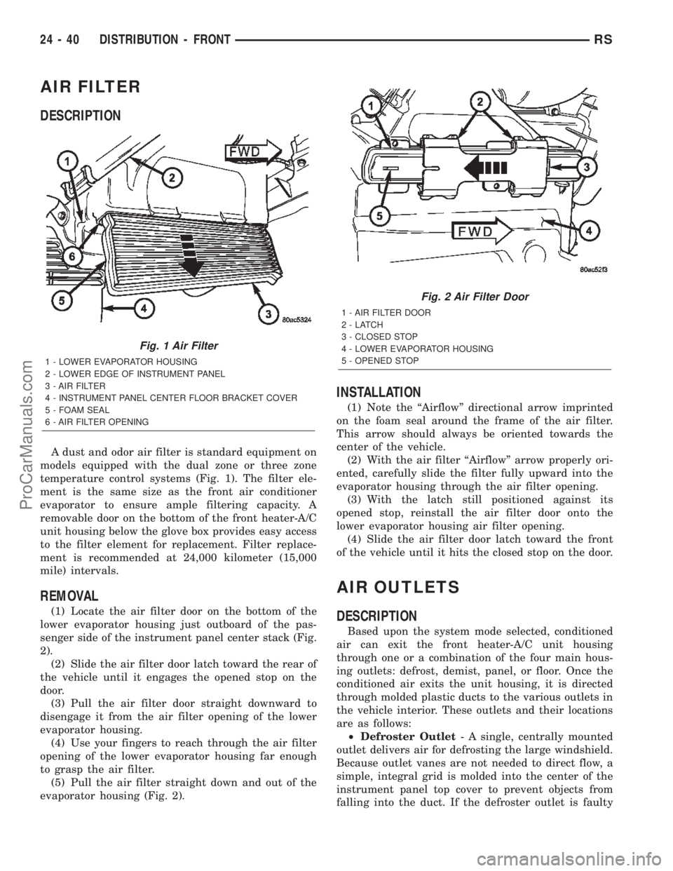
A dust and odor air filter is standard equipment on
models equipped with the dual zone or three zone
temperature control systems (Fig. 1). The filter ele-
ment is the same size as the front air conditioner
evaporator to ensure ample filtering capacity. A
removable door on the bottom of the front heater-A/C
unit housing below the glove box provides easy access
to the filter element for replacement. Filter replace-
ment is recommended at 24,000 kilometer (15,000
mile) intervals.
REMOVAL
(1) Locate the air filter door on the bottom of the
lower evaporator housing just outboard of the pas-
senger side of the instrument panel center stack (Fig.
2).
(2) Slide the air filter door latch toward the rear of
the vehicle until it engages the opened stop on the
door.
(3) Pull the air filter door straight downward to
disengage it from the air filter opening of the lower
evaporator housing.
(4) Use your fingers to reach through the air filter
opening of the lower evaporator housing far enough
to grasp the air filter.
(5) Pull the air filter straight down and out of the
evaporator housing (Fig. 2).
INSTALLATION
(1) Note the ªAirflowº directional arrow imprinted
on the foam seal around the frame of the air filter.
This arrow should always be oriented towards the
center of the vehicle.
(2) With the air filter ªAirflowº arrow properly ori-
ented, carefully slide the filter fully upward into the
evaporator housing through the air filter opening.
(3) With the latch still positioned against its
opened stop, reinstall the air filter door onto the
lower evaporator housing air filter opening.
(4) Slide the air filter door latch toward the front
of the vehicle until it hits the closed stop on the door.
AIR OUTLETS
DESCRIPTION
Based upon the system mode selected, conditioned
air can exit the front heater-A/C unit housing
through one or a combination of the four main hous-
ing outlets: defrost, demist, panel, or floor. Once the
conditioned air exits the unit housing, it is directed
through molded plastic ducts to the various outlets in
the vehicle interior. These outlets and their locations
are as follows:
²Defroster Outlet- A single, centrally mounted
outlet delivers air for defrosting the large windshield.
Because outlet vanes are not needed to direct flow, a
simple, integral grid is molded into the center of the
instrument panel top cover to prevent objects from
falling into the duct. If the defroster outlet is faulty
Fig. 1 Air Filter
1 - LOWER EVAPORATOR HOUSING
2 - LOWER EDGE OF INSTRUMENT PANEL
3 - AIR FILTER
4 - INSTRUMENT PANEL CENTER FLOOR BRACKET COVER
5 - FOAM SEAL
6 - AIR FILTER OPENING
Fig. 2 Air Filter Door
1 - AIR FILTER DOOR
2-LATCH
3 - CLOSED STOP
4 - LOWER EVAPORATOR HOUSING
5 - OPENED STOP
24 - 40 DISTRIBUTION - FRONTRS
ProCarManuals.com