2002 CHRYSLER TOWN AND COUNTRY transmission removal
[x] Cancel search: transmission removalPage 1579 of 2399
ASSEMBLY...........................115
SHIFT INTERLOCK SOLENOID
DESCRIPTION........................115
OPERATION..........................115
DIAGNOSIS AND TESTING - BRAKE/
TRANSMISSION SHIFT INTERLOCK
SOLENOID..........................117
REMOVAL............................117
INSTALLATION........................118
SOLENOID - TCC
DESCRIPTION........................119
OPERATION..........................119
REMOVAL............................119
INSTALLATION........................120
THROTTLE VALVE CABLE
REMOVAL............................120
INSTALLATION........................121
ADJUSTMENTS
THROTTLE VALVE LINKAGE
ADJUSTMENT.......................122
TORQUE CONVERTER
DESCRIPTION........................122
OPERATION..........................126
REMOVAL............................127
INSTALLATION........................127
TRANSFER SYSTEM - OUTPUT SHAFT/GEAR/
BEARING
REMOVAL............................128INSTALLATION........................131
ADJUSTMENTS
ADJUSTMENT - OUTPUT SHAFT BEARING . 135
TRANSFER SYSTEM - TRANSFER SHAFT/
GEAR/BEARING
REMOVAL............................137
INSTALLATION........................141
ADJUSTMENTS
ADJUSTMENT - TRANSFER SHAFT
BEARING...........................145
VALVE BODY
REMOVAL............................146
DISASSEMBLY........................148
CLEANING...........................154
INSPECTION.........................155
ASSEMBLY...........................155
INSTALLATION........................158
ADJUSTMENTS
HYDRAULIC CONTROL PRESSURE
ADJUSTMENTS......................160
VEHICLE SPEED SENSOR/PINION GEAR
REMOVAL............................160
INSTALLATION........................160
31TH AUTOMATIC
TRANSAXLE
DESCRIPTION
This transaxle combines torque converter, three
speed transmission, final drive gearing, and differen-
tial into a front wheel drive system.
Within this transaxle, there are three primary
areas:
(1) Main center line plus valve body.
(2) Transfer shaft center line (includes governor
and parking sprag).
(3) Differential center line.
Center distances between the main rotating parts
in these three areas are held precise to maintain a
low noise level.
The torque converter, transaxle area, and differen-
tial are housed in an integral aluminum die casting.
The differential oil sump is common with the
transaxle sump. Separate filling of the differen-
tial is NOT necessary.
The torque converter is attached to the crankshaft
through a flexible driving plate. Cooling of the con-
verter is accomplished by circulating the transaxle
fluid through a remote cooler. There are two types of
coolers used. An oil-to-water type cooler located in
the radiator side tank and/or an oil-to-air heatexchanger. The torque converter assembly is a sealed
unit that cannot be disassembled.
The transaxle fluid is filtered by an internal filter
attached to the lower side of the valve body assembly.
Engine torque is transmitted to the torque con-
verter and then through the input shaft to multiple-
disc clutches in the transaxle. The power flow
depends on the application of the clutches and bands.
Refer to Elements in Use Chart in Diagnosis and
Tests section.
The transaxle consists of:
²Two multiple-disc clutches
²An overrunning clutch
²Two servos
²A hydraulic accumulator
²Two bands
²Two planetary gear sets
This provides three forward ratios and a reverse
ratio. The common sun gear of the planetary gear
sets is connected to the front clutch by a driving
shell. The driving shell is splined to the sun gear and
front clutch retainer. The hydraulic system consists
of an oil pump and a single valve body which con-
tains all of the valves except the governor valves.
The transaxle sump and differential sump are both
vented through the dipstick. Output torque from the
main center line is delivered through helical gears to
the transfer shaft. This gear set is a factor in the
transaxle final drive (axle) ratio. The shaft also car-
21 - 22 31TH AUTOMATIC TRANSAXLERS
ProCarManuals.com
Page 1592 of 2399
DIAGNOSIS AND TESTING - TORQUE
CONVERTER HOUSING FLUID LEAKAGE
When diagnosing converter housing fluid leaks,
three actions must be taken before repair:
(1) Verify proper transmission fluid level.
(2) Verify that the leak originates from the con-
verter housing area and is transmission fluid.
(3) Determine the true source of the leak.
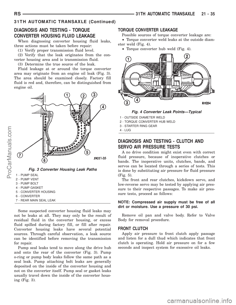
Fluid leakage at or around the torque converter
area may originate from an engine oil leak (Fig. 3).
The area should be examined closely. Factory fill
fluid is red and, therefore, can be distinguished from
engine oil.
Some suspected converter housing fluid leaks may
not be leaks at all. They may only be the result of
residual fluid in the converter housing, or excess
fluid spilled during factory fill, or fill after repair.
Converter housing leaks have several potential
sources. Through careful observation, a leak source
can be identified before removing the transmission
for repair.
Pump seal leaks tend to move along the drive hub
and onto the rear of the converter (Fig. 3). Pump
o-ring or pump body leaks follow the same path as a
seal leak. Pump attaching bolt leaks are generally
deposited on the inside of the converter housing and
not on the converter itself. Pump seal or gasket leaks
usually travel down the inside of the converter hous-
ing (Fig. 3).
TORQUE CONVERTER LEAKAGE
Possible sources of torque converter leakage are:
²Torque converter weld leaks at the outside diam-
eter weld (Fig. 4).
²Torque converter hub weld (Fig. 4).
DIAGNOSIS AND TESTING - CLUTCH AND
SERVO AIR PRESSURE TESTS
A no drive condition might exist even with correct
fluid pressure, because of inoperative clutches or
bands. The inoperative units, clutches, bands, and
servos can be located through a series of tests. This
is done by substituting air pressure for fluid pressure
(Fig. 5).
The front and rear clutches, kickdown servo, and
low-reverse servo may be tested by applying air pres-
sure to their respective passages. To make air pres-
sure tests, proceed as follows:
NOTE: Compressed air supply must be free of all
dirt or moisture. Use a pressure of 30 psi.
Remove oil pan and valve body. Refer to Valve
Body for removal procedure.
FRONT CLUTCH
Apply air pressure to front clutch apply passage
and listen for a dull thud which indicates that front
clutch is operating. Hold air pressure on for a few
seconds and inspect system for excessive oil leaks.
Fig. 3 Converter Housing Leak Paths
1 - PUMP SEAL
2 - PUMP VENT
3 - PUMP BOLT
4 - PUMP GASKET
5 - CONVERTER HOUSING
6 - CONVERTER
7 - REAR MAIN SEAL LEAK
Fig. 4 Converter Leak PointsÐTypical
1 - OUTSIDE DIAMETER WELD
2 - TORQUE CONVERTER HUB WELD
3 - STARTER RING GEAR
4 - LUG
RS31TH AUTOMATIC TRANSAXLE21-35
31TH AUTOMATIC TRANSAXLE (Continued)
ProCarManuals.com
Page 1603 of 2399
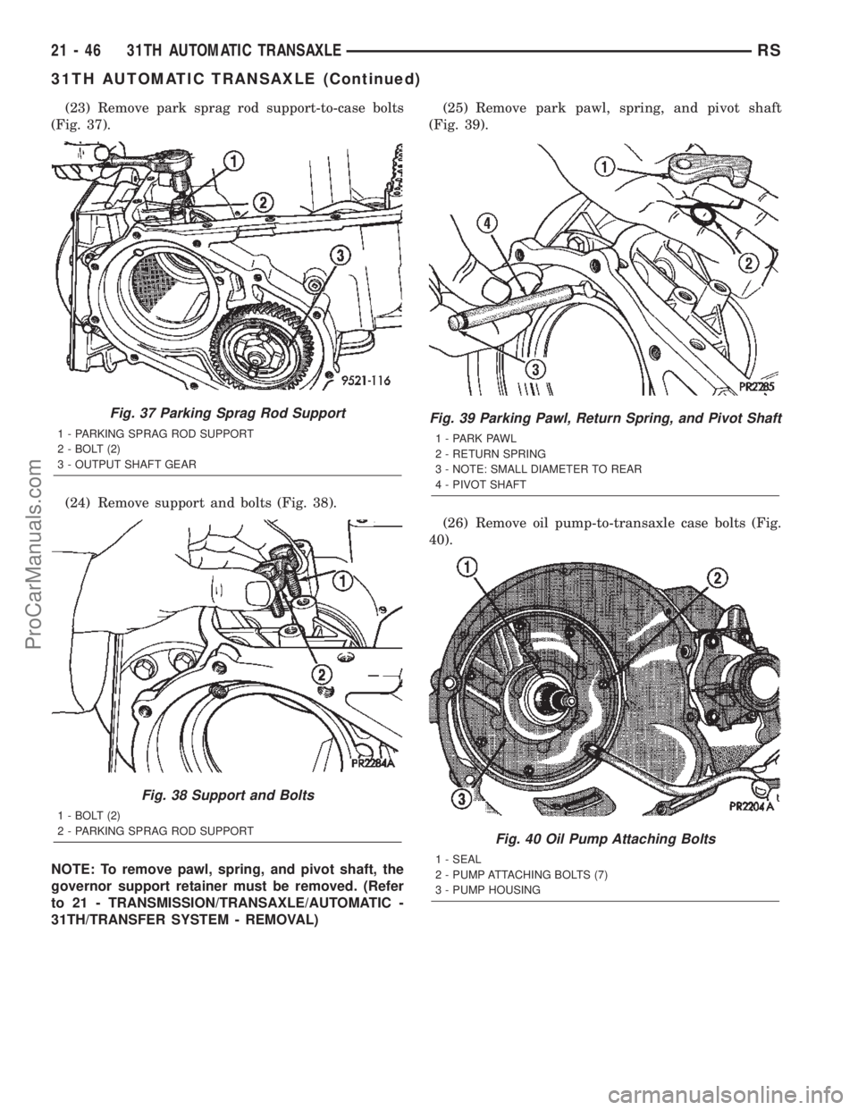
(23) Remove park sprag rod support-to-case bolts
(Fig. 37).
(24) Remove support and bolts (Fig. 38).
NOTE: To remove pawl, spring, and pivot shaft, the
governor support retainer must be removed. (Refer
to 21 - TRANSMISSION/TRANSAXLE/AUTOMATIC -
31TH/TRANSFER SYSTEM - REMOVAL)(25) Remove park pawl, spring, and pivot shaft
(Fig. 39).
(26) Remove oil pump-to-transaxle case bolts (Fig.
40).
Fig. 37 Parking Sprag Rod Support
1 - PARKING SPRAG ROD SUPPORT
2 - BOLT (2)
3 - OUTPUT SHAFT GEAR
Fig. 38 Support and Bolts
1 - BOLT (2)
2 - PARKING SPRAG ROD SUPPORT
Fig. 39 Parking Pawl, Return Spring, and Pivot Shaft
1 - PARK PAWL
2 - RETURN SPRING
3 - NOTE: SMALL DIAMETER TO REAR
4 - PIVOT SHAFT
Fig. 40 Oil Pump Attaching Bolts
1 - SEAL
2 - PUMP ATTACHING BOLTS (7)
3 - PUMP HOUSING
21 - 46 31TH AUTOMATIC TRANSAXLERS
31TH AUTOMATIC TRANSAXLE (Continued)
ProCarManuals.com
Page 1664 of 2399
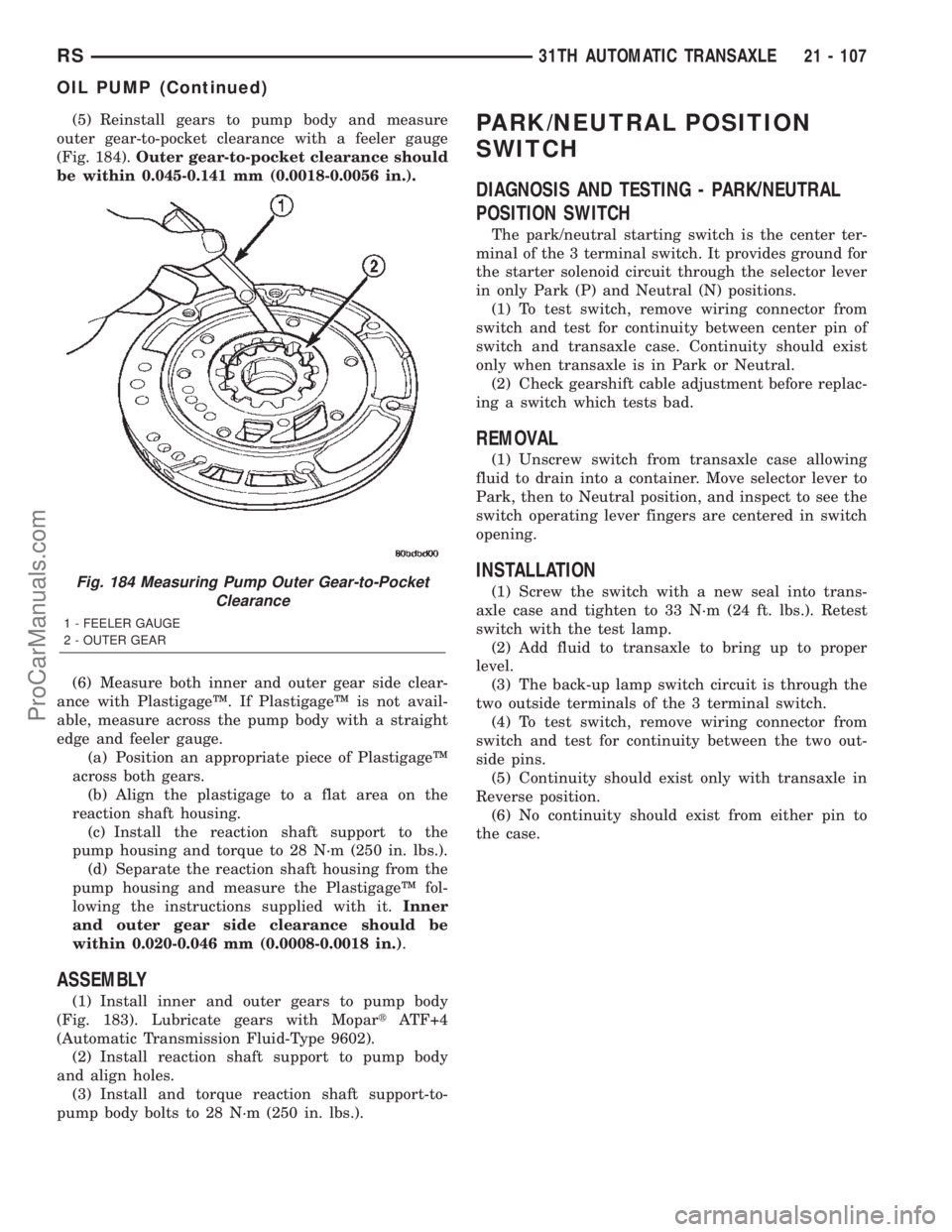
(5) Reinstall gears to pump body and measure
outer gear-to-pocket clearance with a feeler gauge
(Fig. 184).Outer gear-to-pocket clearance should
be within 0.045-0.141 mm (0.0018-0.0056 in.).
(6) Measure both inner and outer gear side clear-
ance with PlastigageŸ. If PlastigageŸ is not avail-
able, measure across the pump body with a straight
edge and feeler gauge.
(a) Position an appropriate piece of PlastigageŸ
across both gears.
(b) Align the plastigage to a flat area on the
reaction shaft housing.
(c) Install the reaction shaft support to the
pump housing and torque to 28 N´m (250 in. lbs.).
(d) Separate the reaction shaft housing from the
pump housing and measure the PlastigageŸ fol-
lowing the instructions supplied with it.Inner
and outer gear side clearance should be
within 0.020-0.046 mm (0.0008-0.0018 in.).
ASSEMBLY
(1) Install inner and outer gears to pump body
(Fig. 183). Lubricate gears with MopartATF+4
(Automatic Transmission Fluid-Type 9602).
(2) Install reaction shaft support to pump body
and align holes.
(3) Install and torque reaction shaft support-to-
pump body bolts to 28 N´m (250 in. lbs.).
PARK/NEUTRAL POSITION
SWITCH
DIAGNOSIS AND TESTING - PARK/NEUTRAL
POSITION SWITCH
The park/neutral starting switch is the center ter-
minal of the 3 terminal switch. It provides ground for
the starter solenoid circuit through the selector lever
in only Park (P) and Neutral (N) positions.
(1) To test switch, remove wiring connector from
switch and test for continuity between center pin of
switch and transaxle case. Continuity should exist
only when transaxle is in Park or Neutral.
(2) Check gearshift cable adjustment before replac-
ing a switch which tests bad.
REMOVAL
(1) Unscrew switch from transaxle case allowing
fluid to drain into a container. Move selector lever to
Park, then to Neutral position, and inspect to see the
switch operating lever fingers are centered in switch
opening.
INSTALLATION
(1) Screw the switch with a new seal into trans-
axle case and tighten to 33 N´m (24 ft. lbs.). Retest
switch with the test lamp.
(2) Add fluid to transaxle to bring up to proper
level.
(3) The back-up lamp switch circuit is through the
two outside terminals of the 3 terminal switch.
(4) To test switch, remove wiring connector from
switch and test for continuity between the two out-
side pins.
(5) Continuity should exist only with transaxle in
Reverse position.
(6) No continuity should exist from either pin to
the case.Fig. 184 Measuring Pump Outer Gear-to-Pocket
Clearance
1 - FEELER GAUGE
2 - OUTER GEAR
RS31TH AUTOMATIC TRANSAXLE21 - 107
OIL PUMP (Continued)
ProCarManuals.com
Page 1674 of 2399
DIAGNOSIS AND TESTING - BRAKE/
TRANSMISSION SHIFT INTERLOCK SOLENOID
For intended BTSI system operation, refer to the
following chart:
ACTION EXPECTED RESPONSE
1. Turn key to the9OFF9
position.1. Shifter CAN be shifted
out of park with brake
pedal applied.
2. Turn key to the
9ON/RUN9position.2. Shifter CANNOT be
shifted out of park.
3. Turn key to the
9ON/RUN9position and
depress the brake pedal.3. Shifter CAN be shifted
out of park.
4. Leave shifter in any
gear and try to return key
to the9LOCK9or9ACC9
position.4. Key cannot be
returned to the9LOCK9or
9ACC9position.
5. Return shifter to
9PARK9and try to remove
the key.5. Key can be removed
(after returning to9LOCK9
position).
6. With the key removed,
try to shift out of9PARK9.6. Shifter cannot be
shifted out of9PARK9.
NOTE: Any failure to meet these expected
responses requires system repair. Refer to the
appropriate Diagnostic Information.
REMOVAL
(1) Disconnect battery negative cable.
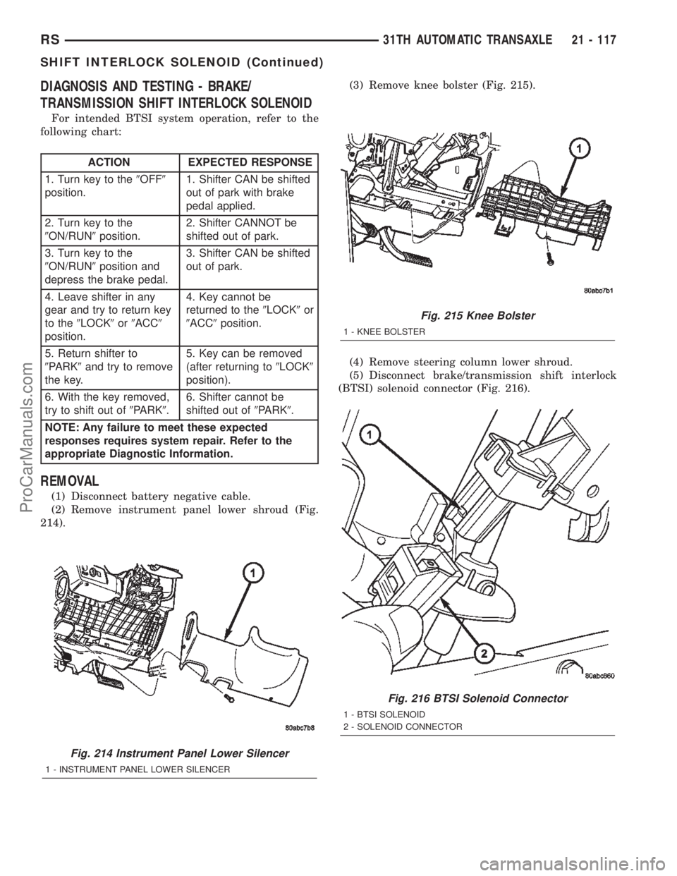
(2) Remove instrument panel lower shroud (Fig.
214).(3) Remove knee bolster (Fig. 215).
(4) Remove steering column lower shroud.
(5) Disconnect brake/transmission shift interlock
(BTSI) solenoid connector (Fig. 216).
Fig. 214 Instrument Panel Lower Silencer
1 - INSTRUMENT PANEL LOWER SILENCER
Fig. 215 Knee Bolster
1 - KNEE BOLSTER
Fig. 216 BTSI Solenoid Connector
1 - BTSI SOLENOID
2 - SOLENOID CONNECTOR
RS31TH AUTOMATIC TRANSAXLE21 - 117
SHIFT INTERLOCK SOLENOID (Continued)
ProCarManuals.com
Page 1676 of 2399
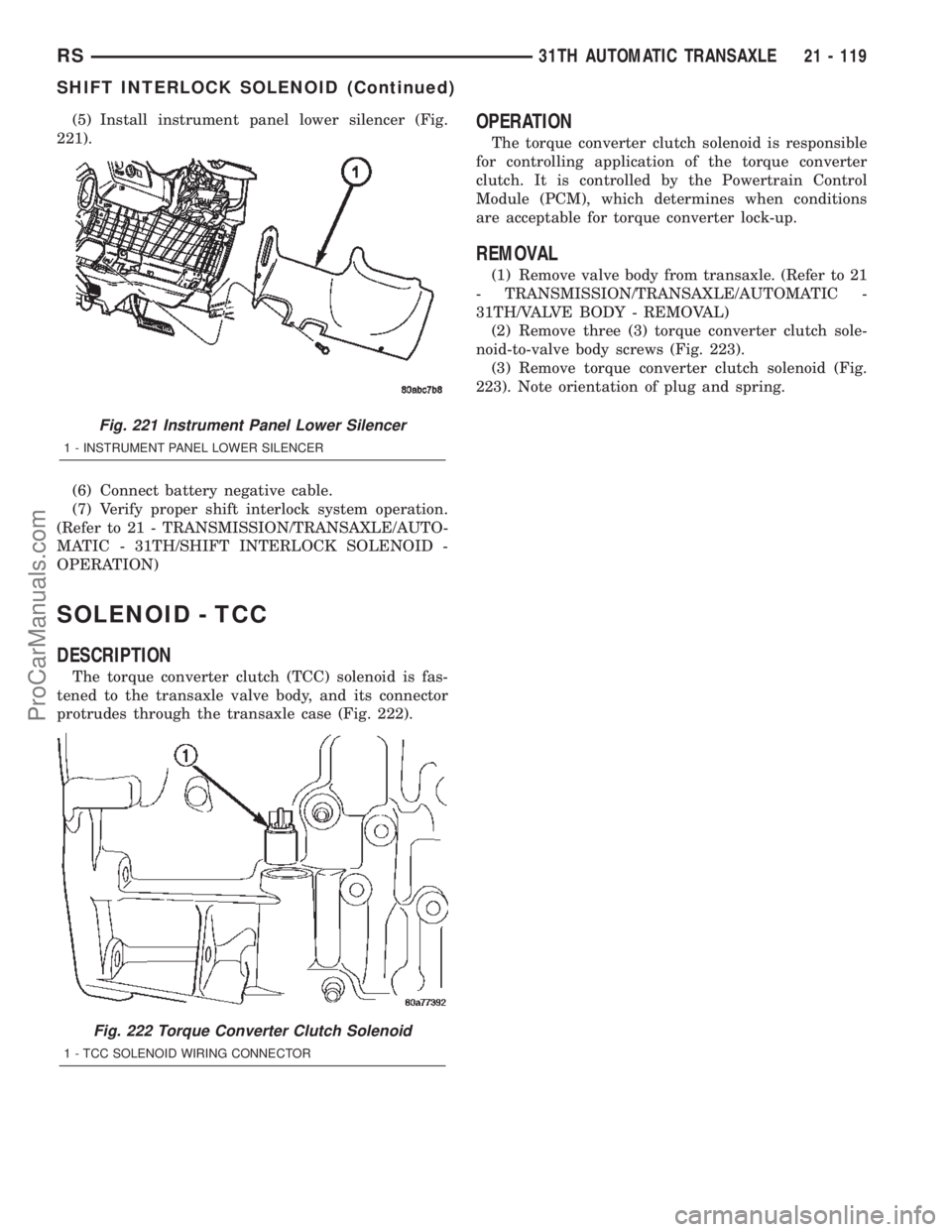
(5) Install instrument panel lower silencer (Fig.
221).
(6) Connect battery negative cable.
(7) Verify proper shift interlock system operation.
(Refer to 21 - TRANSMISSION/TRANSAXLE/AUTO-
MATIC - 31TH/SHIFT INTERLOCK SOLENOID -
OPERATION)
SOLENOID - TCC
DESCRIPTION
The torque converter clutch (TCC) solenoid is fas-
tened to the transaxle valve body, and its connector
protrudes through the transaxle case (Fig. 222).
OPERATION
The torque converter clutch solenoid is responsible
for controlling application of the torque converter
clutch. It is controlled by the Powertrain Control
Module (PCM), which determines when conditions
are acceptable for torque converter lock-up.
REMOVAL
(1) Remove valve body from transaxle. (Refer to 21
- TRANSMISSION/TRANSAXLE/AUTOMATIC -
31TH/VALVE BODY - REMOVAL)
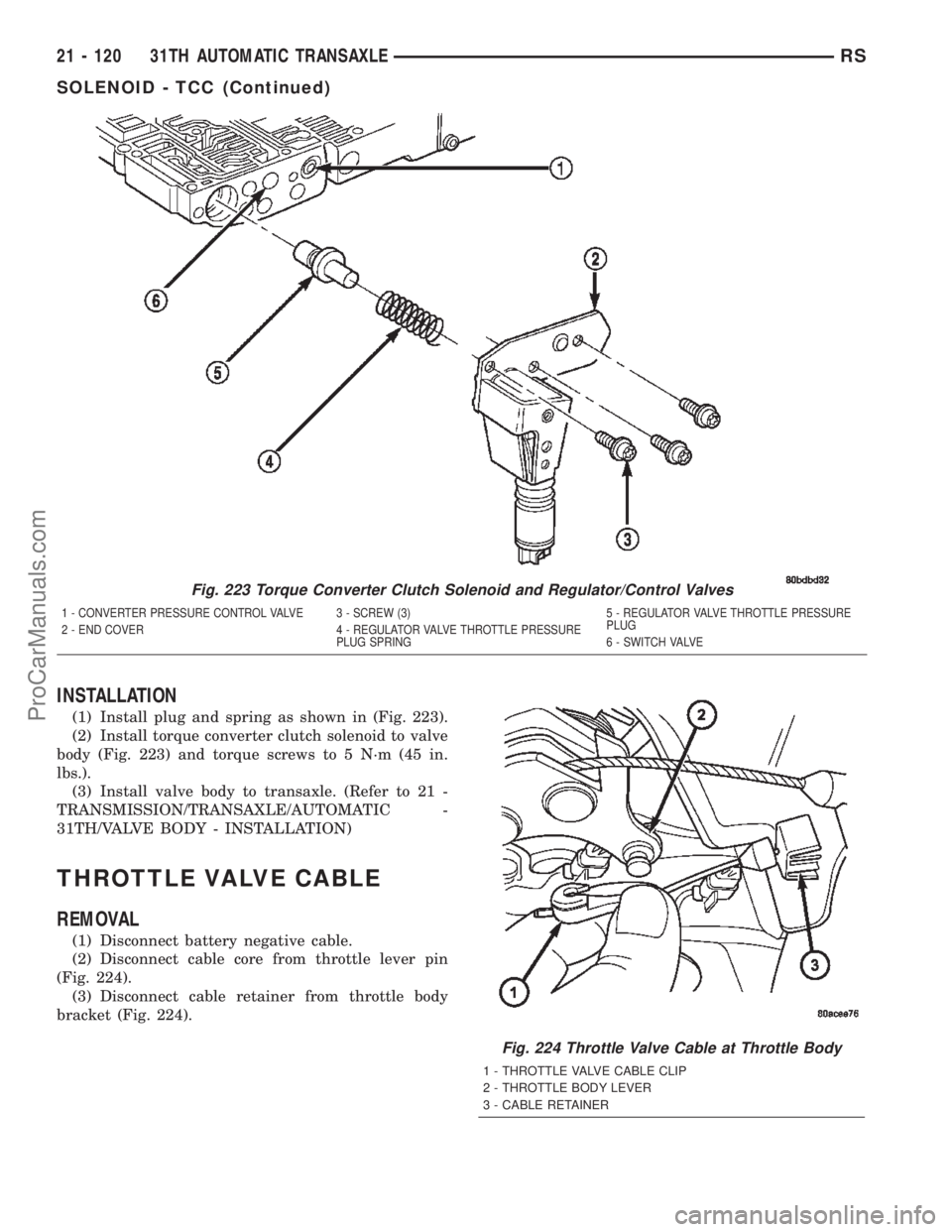
(2) Remove three (3) torque converter clutch sole-
noid-to-valve body screws (Fig. 223).
(3) Remove torque converter clutch solenoid (Fig.
223). Note orientation of plug and spring.
Fig. 221 Instrument Panel Lower Silencer
1 - INSTRUMENT PANEL LOWER SILENCER
Fig. 222 Torque Converter Clutch Solenoid
1 - TCC SOLENOID WIRING CONNECTOR
RS31TH AUTOMATIC TRANSAXLE21 - 119
SHIFT INTERLOCK SOLENOID (Continued)
ProCarManuals.com
Page 1677 of 2399
INSTALLATION
(1) Install plug and spring as shown in (Fig. 223).
(2) Install torque converter clutch solenoid to valve
body (Fig. 223) and torque screws to 5 N´m (45 in.
lbs.).
(3) Install valve body to transaxle. (Refer to 21 -
TRANSMISSION/TRANSAXLE/AUTOMATIC -
31TH/VALVE BODY - INSTALLATION)
THROTTLE VALVE CABLE
REMOVAL
(1) Disconnect battery negative cable.
(2) Disconnect cable core from throttle lever pin
(Fig. 224).
(3) Disconnect cable retainer from throttle body
bracket (Fig. 224).
Fig. 223 Torque Converter Clutch Solenoid and Regulator/Control Valves
1 - CONVERTER PRESSURE CONTROL VALVE 3 - SCREW (3) 5 - REGULATOR VALVE THROTTLE PRESSURE
PLUG
2 - END COVER 4 - REGULATOR VALVE THROTTLE PRESSURE
PLUG SPRING 6 - SWITCH VALVE
Fig. 224 Throttle Valve Cable at Throttle Body
1 - THROTTLE VALVE CABLE CLIP
2 - THROTTLE BODY LEVER
3 - CABLE RETAINER
21 - 120 31TH AUTOMATIC TRANSAXLERS
SOLENOID - TCC (Continued)
ProCarManuals.com
Page 1684 of 2399
STATOR
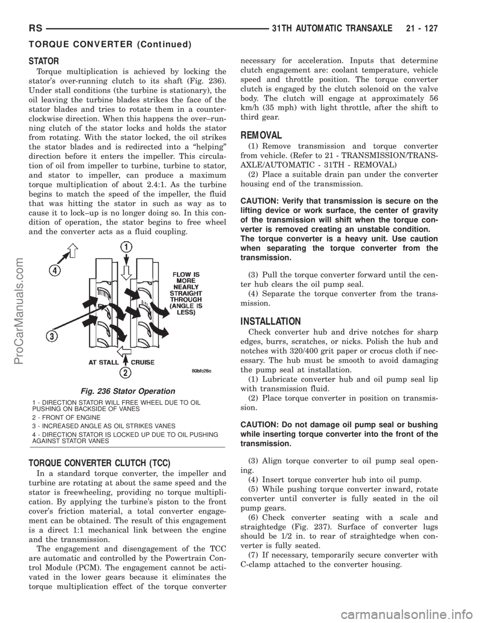
Torque multiplication is achieved by locking the
stator's over-running clutch to its shaft (Fig. 236).
Under stall conditions (the turbine is stationary), the
oil leaving the turbine blades strikes the face of the
stator blades and tries to rotate them in a counter-
clockwise direction. When this happens the over±run-
ning clutch of the stator locks and holds the stator
from rotating. With the stator locked, the oil strikes
the stator blades and is redirected into a ªhelpingº
direction before it enters the impeller. This circula-
tion of oil from impeller to turbine, turbine to stator,
and stator to impeller, can produce a maximum
torque multiplication of about 2.4:1. As the turbine
begins to match the speed of the impeller, the fluid
that was hitting the stator in such as way as to
cause it to lock±up is no longer doing so. In this con-
dition of operation, the stator begins to free wheel
and the converter acts as a fluid coupling.
TORQUE CONVERTER CLUTCH (TCC)
In a standard torque converter, the impeller and
turbine are rotating at about the same speed and the
stator is freewheeling, providing no torque multipli-
cation. By applying the turbine's piston to the front
cover's friction material, a total converter engage-
ment can be obtained. The result of this engagement
is a direct 1:1 mechanical link between the engine
and the transmission.
The engagement and disengagement of the TCC
are automatic and controlled by the Powertrain Con-
trol Module (PCM). The engagement cannot be acti-
vated in the lower gears because it eliminates the
torque multiplication effect of the torque converternecessary for acceleration. Inputs that determine
clutch engagement are: coolant temperature, vehicle
speed and throttle position. The torque converter
clutch is engaged by the clutch solenoid on the valve
body. The clutch will engage at approximately 56
km/h (35 mph) with light throttle, after the shift to
third gear.
REMOVAL
(1) Remove transmission and torque converter
from vehicle. (Refer to 21 - TRANSMISSION/TRANS-
AXLE/AUTOMATIC - 31TH - REMOVAL)
(2) Place a suitable drain pan under the converter
housing end of the transmission.
CAUTION: Verify that transmission is secure on the
lifting device or work surface, the center of gravity
of the transmission will shift when the torque con-
verter is removed creating an unstable condition.
The torque converter is a heavy unit. Use caution
when separating the torque converter from the
transmission.
(3) Pull the torque converter forward until the cen-
ter hub clears the oil pump seal.
(4) Separate the torque converter from the trans-
mission.
INSTALLATION
Check converter hub and drive notches for sharp
edges, burrs, scratches, or nicks. Polish the hub and
notches with 320/400 grit paper or crocus cloth if nec-
essary. The hub must be smooth to avoid damaging
the pump seal at installation.
(1) Lubricate converter hub and oil pump seal lip
with transmission fluid.
(2) Place torque converter in position on transmis-
sion.
CAUTION: Do not damage oil pump seal or bushing
while inserting torque converter into the front of the
transmission.
(3) Align torque converter to oil pump seal open-
ing.
(4) Insert torque converter hub into oil pump.
(5) While pushing torque converter inward, rotate
converter until converter is fully seated in the oil
pump gears.
(6) Check converter seating with a scale and
straightedge (Fig. 237). Surface of converter lugs
should be 1/2 in. to rear of straightedge when con-
verter is fully seated.
(7) If necessary, temporarily secure converter with
C-clamp attached to the converter housing.
Fig. 236 Stator Operation
1 - DIRECTION STATOR WILL FREE WHEEL DUE TO OIL
PUSHING ON BACKSIDE OF VANES
2 - FRONT OF ENGINE
3 - INCREASED ANGLE AS OIL STRIKES VANES
4 - DIRECTION STATOR IS LOCKED UP DUE TO OIL PUSHING
AGAINST STATOR VANES
RS31TH AUTOMATIC TRANSAXLE21 - 127
TORQUE CONVERTER (Continued)
ProCarManuals.com