2002 CHRYSLER TOWN AND COUNTRY transmission removal
[x] Cancel search: transmission removalPage 1905 of 2399
AXLE SEALS
REMOVAL
(1) Raise vehicle on hoist.
(2) Remove one or both front halfshaft assemblies.
(Refer to 3 - DIFFERENTIAL & DRIVELINE/HALF
SHAFT - REMOVAL)
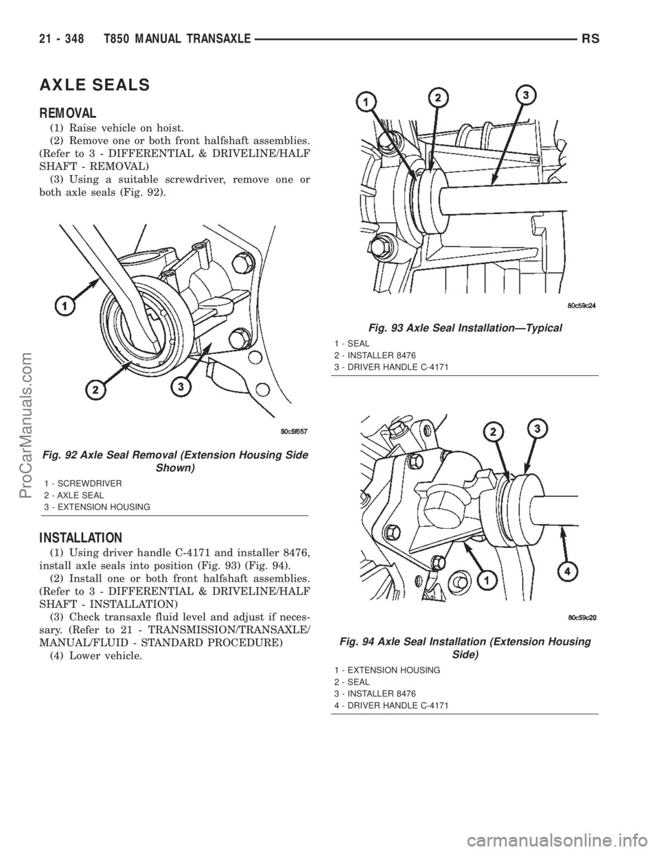
(3) Using a suitable screwdriver, remove one or
both axle seals (Fig. 92).
INSTALLATION
(1) Using driver handle C-4171 and installer 8476,
install axle seals into position (Fig. 93) (Fig. 94).
(2) Install one or both front halfshaft assemblies.
(Refer to 3 - DIFFERENTIAL & DRIVELINE/HALF
SHAFT - INSTALLATION)
(3) Check transaxle fluid level and adjust if neces-
sary. (Refer to 21 - TRANSMISSION/TRANSAXLE/
MANUAL/FLUID - STANDARD PROCEDURE)
(4) Lower vehicle.
Fig. 92 Axle Seal Removal (Extension Housing Side
Shown)
1 - SCREWDRIVER
2 - AXLE SEAL
3 - EXTENSION HOUSING
Fig. 93 Axle Seal InstallationÐTypical
1 - SEAL
2 - INSTALLER 8476
3 - DRIVER HANDLE C-4171
Fig. 94 Axle Seal Installation (Extension Housing
Side)
1 - EXTENSION HOUSING
2 - SEAL
3 - INSTALLER 8476
4 - DRIVER HANDLE C-4171
21 - 348 T850 MANUAL TRANSAXLERS
ProCarManuals.com
Page 1916 of 2399
STANDARD PROCEDURE - FLUID DRAIN AND
FILL
NOTE: For proper fluid change intervals, (Refer to
LUBRICATION & MAINTENANCE/MAINTENANCE
SCHEDULES - DESCRIPTION)
The fluid required in this transaxle is Mopart
ATF+4 (Automatic Transmission FluidÐType 9602).
Use of substitute fluids may result in improper
transaxle operation and/or failure.
FLUID DRAIN
(1) Raise vehicle on hoist.
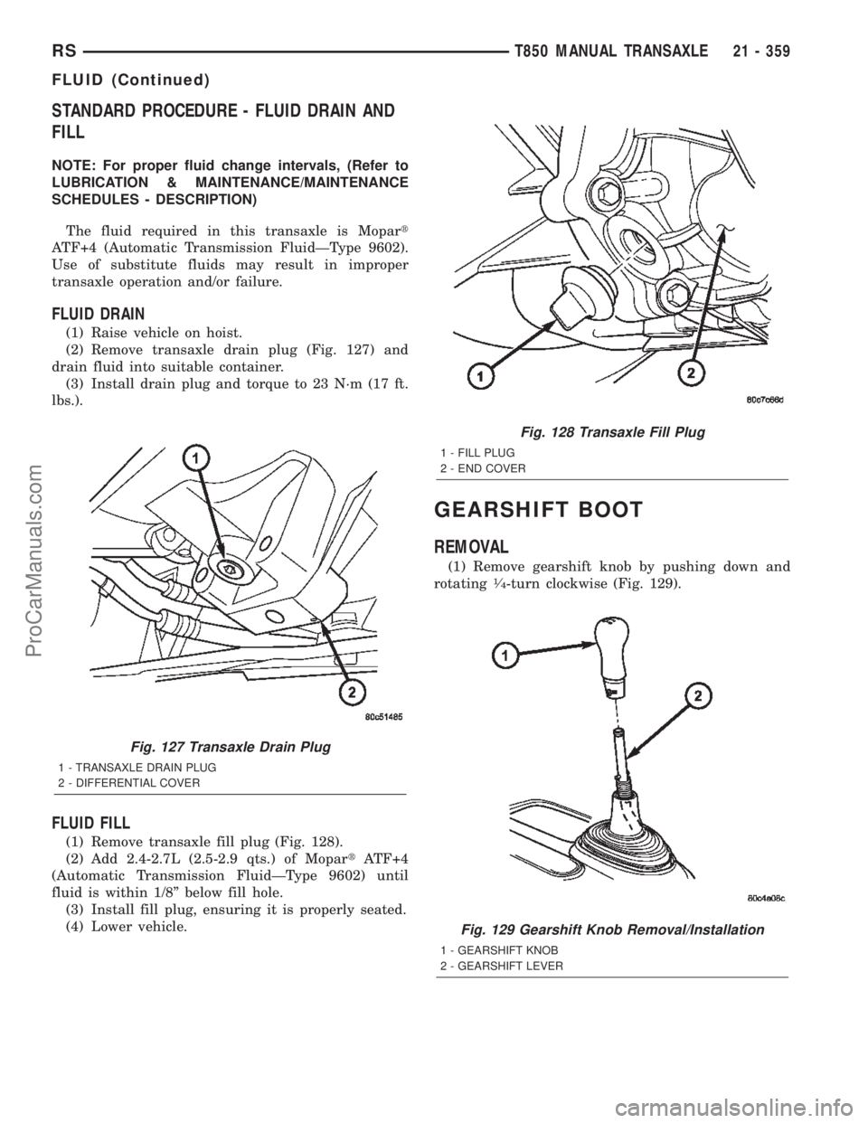
(2) Remove transaxle drain plug (Fig. 127) and
drain fluid into suitable container.
(3) Install drain plug and torque to 23 N´m (17 ft.
lbs.).
FLUID FILL
(1) Remove transaxle fill plug (Fig. 128).
(2) Add 2.4-2.7L (2.5-2.9 qts.) of MopartATF+4
(Automatic Transmission FluidÐType 9602) until
fluid is within 1/8º below fill hole.
(3) Install fill plug, ensuring it is properly seated.
(4) Lower vehicle.
GEARSHIFT BOOT
REMOVAL
(1) Remove gearshift knob by pushing down and
rotating1¤4-turn clockwise (Fig. 129).
Fig. 127 Transaxle Drain Plug
1 - TRANSAXLE DRAIN PLUG
2 - DIFFERENTIAL COVER
Fig. 128 Transaxle Fill Plug
1 - FILL PLUG
2 - END COVER
Fig. 129 Gearshift Knob Removal/Installation
1 - GEARSHIFT KNOB
2 - GEARSHIFT LEVER
RST850 MANUAL TRANSAXLE21 - 359
FLUID (Continued)
ProCarManuals.com
Page 2048 of 2399
INSTALLATION
(1) Install the glove box latch striker.
(2) Install the screws holding latch striker to
instrument panel.
(3) Close glove box door.
INSTRUMENT PANEL
ASSEMBLY
REMOVAL
(1) Disconnect and isolate the battery negative
cable.
(2) Remove the lower console:
(a) Remove six retaining screws.
(b) Pull rearward and disconnect the auxiliary
power outlet.
(c) Remove lower console from vehicle.
(3) Remove the bolts attaching the lower supports
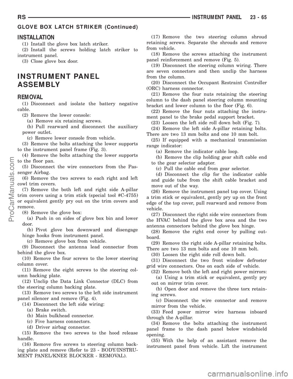
to the instrument panel frame (Fig. 3).
(4) Remove the bolts attaching the lower supports
to the floor pan.
(5) Disconnect the wire connectors from the Pas-
senger Airbag.
(6) Remove the two screws to each right and left
cowl trim covers.
(7) Remove the both left and right side A-pillar
trim covers using a trim stick (special tool #C-4755)
or equivalent gently pry out on the trim covers and
remove.
(8) Remove the glove box:
(a) Push in on sides of glove box bin and lower
door.
(b) Pivot glove box downward and disengage
hinge hooks from instrument panel.
(c) Remove glove box from vehicle.
(9) Disconnect the antenna lead connector from
behind the glove box.
(10) Remove the four screws to the lower steering
column cover.
(11) Remove the eight screws to the steering col-
umn backing plate.
(12) Unclip the Data Link Connector (DLC) from
the steering column backing plate.
(13) Remove two screws to the left side instrument
panel silencer and remove (Fig. 4).
(14) Disconnect the left side wiring:
(a) Brake switch.
(b) Main bulkhead connector.
(c) Five harness connectors.
(d) Driver airbag connector.
(15) Remove the two screws to the hood release
handle.
(16) Remove five screws to steering column back-
ing plate and remove (Refer to 23 - BODY/INSTRU-
MENT PANEL/KNEE BLOCKER - REMOVAL).(17) Remove the two steering column shroud
retaining screws. Separate the shrouds and remove
from vehicle.
(18) Remove the screws attaching the instrument
panel reinforcement and remove (Fig. 5).
(19) Disconnect the steering column wiring. There
are seven connectors and then unclip the harness
from the column.
(20) Disconnect the Occupant Restraint Controller
(ORC) harness connector.
(21) Remove the four nuts retaining the steering
column to the dash panel steering column mounting
bracket and lower column to the floor (Fig. 6).
(22) Remove the four nuts attaching the instru-
ment panel to the brake pedal support bracket.
(23) Loosen the left side roll down bolt (Fig. 7).
(24) Remove the left side A-pillar retaining bolts.
There are two 13 mm bolts and one 10 mm bolt.
(25) If equipped with a mechanical transmission
range indicator:
(a) Remove the indicator cable loop.
(b) Remove the clip holding gear shift cable end
to the gear selector adapter.
(c) Pull the cable end from gear selector.
(d) Disconnect the clip for the indicator cable
and guide tube from the shift cable bracket and
move out of the way.
(26) Remove the instrument panel top cover. Using
a trim stick or equivalent, gently pry up on the front
edge of the top cover, pull rearward and remove from
vehicle.
(27) Disconnect the right side wire connectors from
the HVAC behind the glove box area and the two
antenna connectors behind the glove box hinge.
(28) Remove the right end cover by pulling out-
board.
(29) Remove the right side A-pillar retaining bolts.
There are two 13 mm bolts and one 10 mm bolt.
(30) Loosen the right side roll down bolt.
(31) Disconnect the two front window defroster
grid wire connectors. One on each side of vehicle.
(32) Remove both the left and right power mirrors:
(a) Using a trim stick or equivalent, gently pry
out on mirror trim cover.
(b) Open door and remove the three torx retain-
ing screws.
(c) Disconnect the wire connector and remove
mirror from the vehicle.
(33) Feed power mirror wire harness inboard
through the A-pillar.
(34) Remove the bolts attaching the instrument
panel frame to the dash panel below windshield
opening.
(35) With the help of an assistant remove the
instrument panel from vehicle. Lift the instrument
RSINSTRUMENT PANEL23-65
GLOVE BOX LATCH STRIKER (Continued)
ProCarManuals.com
Page 2050 of 2399
INSTALLATION
(1) With the help of an assistant place the instru-
ment panel into vehicle on roll down bolts. As you
roll the instrument panel up, lift the instrument
panel up so the duct work does not bind or bend and
you can set it down on the HVAC housing to get the
proper seal at the distribution duct. Get one bolt
started in the dash panel.
(2) Install the left and right side A-pillar retaining
bolts. There are two 13 mm bolts and one 10 mm
bolt. The 10 mm bolts need to be installed first to
insure proper positioning of the Instrument panel in
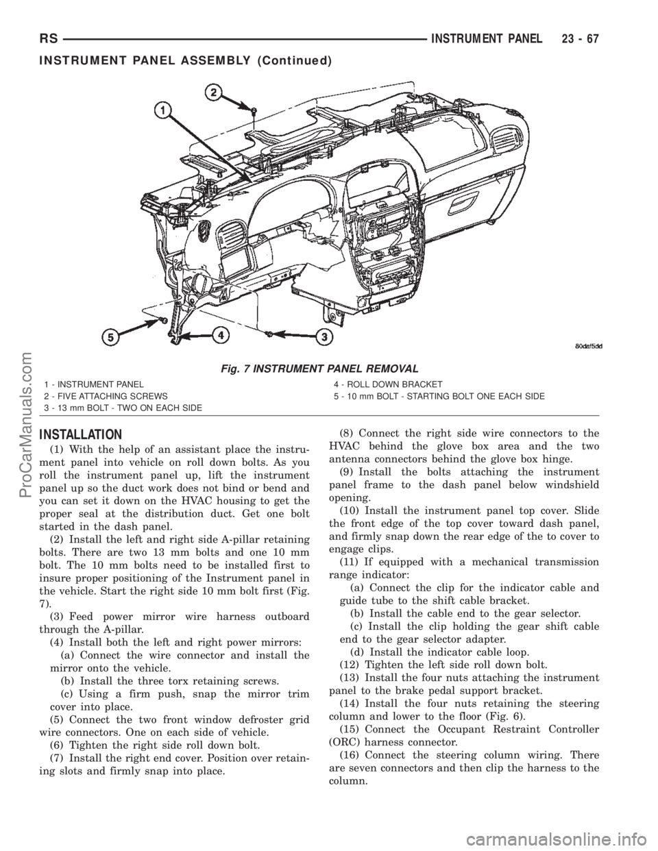
the vehicle. Start the right side 10 mm bolt first (Fig.
7).
(3) Feed power mirror wire harness outboard
through the A-pillar.
(4) Install both the left and right power mirrors:
(a) Connect the wire connector and install the
mirror onto the vehicle.
(b) Install the three torx retaining screws.
(c) Using a firm push, snap the mirror trim
cover into place.
(5) Connect the two front window defroster grid
wire connectors. One on each side of vehicle.
(6) Tighten the right side roll down bolt.
(7) Install the right end cover. Position over retain-
ing slots and firmly snap into place.(8) Connect the right side wire connectors to the
HVAC behind the glove box area and the two
antenna connectors behind the glove box hinge.
(9) Install the bolts attaching the instrument
panel frame to the dash panel below windshield
opening.
(10) Install the instrument panel top cover. Slide
the front edge of the top cover toward dash panel,
and firmly snap down the rear edge of the to cover to
engage clips.
(11) If equipped with a mechanical transmission
range indicator:
(a) Connect the clip for the indicator cable and
guide tube to the shift cable bracket.
(b) Install the cable end to the gear selector.
(c) Install the clip holding the gear shift cable
end to the gear selector adapter.
(d) Install the indicator cable loop.
(12) Tighten the left side roll down bolt.
(13) Install the four nuts attaching the instrument
panel to the brake pedal support bracket.
(14) Install the four nuts retaining the steering
column and lower to the floor (Fig. 6).
(15) Connect the Occupant Restraint Controller
(ORC) harness connector.
(16) Connect the steering column wiring. There
are seven connectors and then clip the harness to the
column.
Fig. 7 INSTRUMENT PANEL REMOVAL
1 - INSTRUMENT PANEL
2 - FIVE ATTACHING SCREWS
3 - 13 mm BOLT - TWO ON EACH SIDE4 - ROLL DOWN BRACKET
5 - 10 mm BOLT - STARTING BOLT ONE EACH SIDE
RSINSTRUMENT PANEL23-67
INSTRUMENT PANEL ASSEMBLY (Continued)
ProCarManuals.com
Page 2308 of 2399
FRONT/REFRIGERANT - STANDARD PROCE-
DURE - REFRIGERANT SYSTEM CHARGE).
INSTALLATION - COMPRESSOR MOUNTING
BRACKET - 2.4L ENGINE
(1) Position the compressor mounting bracket onto
the engine.
(2) Install and tighten the four screws that secure
the compressor mounting bracket to the engine.
Tighten the screws to 54 N´m (40 ft. lbs.).
(3) Reinstall the compressor onto the mounting
bracket. (Refer to 24 - HEATING & AIR CONDI-
TIONING/PLUMBING/COMPRESSOR - INSTALLA-
TION).
CONDENSER
DESCRIPTION
The condenser is integral to a cooling module
which includes the radiator, the electric cooling fan,
the fan shroud, air seals and an automatic transmis-
sion oil cooler. The cooling module is located in the
air flow in the front of the engine compartment
behind the radiator grille. The condenser cannot be
repaired or adjusted and, if faulty or damaged, it
must be replaced. The condenser may be removed
from the cooling module for service without removing
the cooling module from the vehicle.
OPERATION
The condenser is a heat exchanger that allows the
high-pressure refrigerant gas being discharged by the
compressor to give up its heat to the air passing over
the condenser fins. When the refrigerant gas gives up
its heat, it condenses. When the refrigerant leaves
the condenser, it has become a high-pressure liquid
refrigerant. The volume of air flowing over the con-
denser fins is critical to the proper cooling perfor-
mance of the air conditioning system. Therefore, it is
important that there are no objects placed in front of
the radiator grille openings in the front of the vehicle
or foreign material on the condenser fins that might
obstruct air flow. Also, any factory-installed air seals
or shrouds must be properly reinstalled following
radiator or condenser service.
REMOVAL
WARNING: REFER TO THE APPLICABLE WARN-
INGS AND CAUTIONS FOR THIS SYSTEM BEFORE
PERFORMING THE FOLLOWING OPERATION.
(Refer to 24 - HEATING & AIR CONDITIONING/
PLUMBING - FRONT - WARNING - A/C PLUMBING)
and (Refer to 24 - HEATING & AIR CONDITIONING/
PLUMBING - FRONT - CAUTION - A/C PLUMBING).NOTE: Before removing the condenser, note the
location of each of the radiator and condenser air
seals. These air seals are used to direct air through
the condenser and radiator. The air seals must be
reinstalled in their proper locations in order for the
air conditioning and engine cooling systems to per-
form as designed.
(1) Recover the refrigerant from the refrigerant
system. (Refer to 24 - HEATING & AIR CONDI-
TIONING/PLUMBING - FRONT/REFRIGERANT -
STANDARD PROCEDURE - REFRIGERANT
RECOVERY).
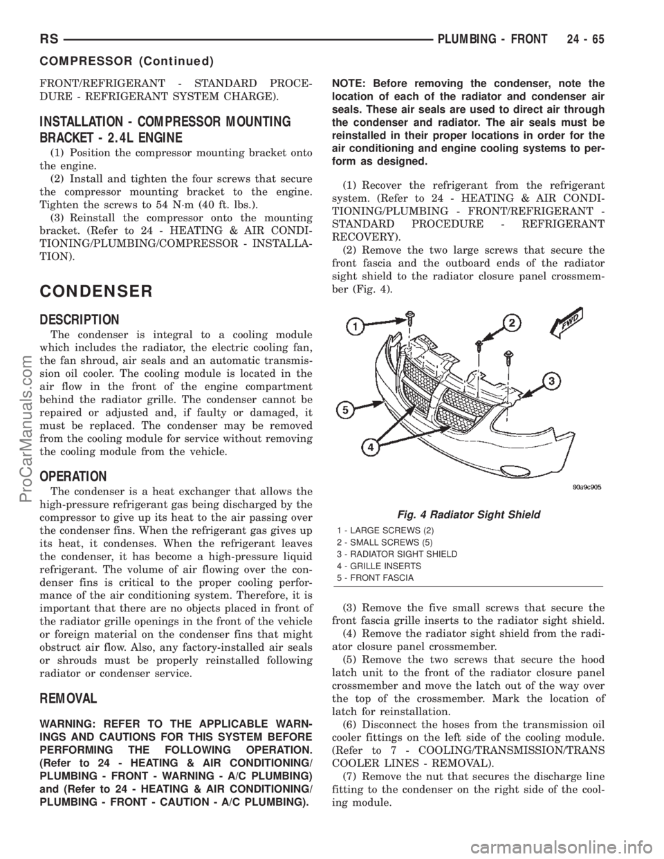
(2) Remove the two large screws that secure the
front fascia and the outboard ends of the radiator
sight shield to the radiator closure panel crossmem-
ber (Fig. 4).
(3) Remove the five small screws that secure the
front fascia grille inserts to the radiator sight shield.
(4) Remove the radiator sight shield from the radi-
ator closure panel crossmember.
(5) Remove the two screws that secure the hood
latch unit to the front of the radiator closure panel
crossmember and move the latch out of the way over
the top of the crossmember. Mark the location of
latch for reinstallation.
(6) Disconnect the hoses from the transmission oil
cooler fittings on the left side of the cooling module.
(Refer to 7 - COOLING/TRANSMISSION/TRANS
COOLER LINES - REMOVAL).
(7) Remove the nut that secures the discharge line
fitting to the condenser on the right side of the cool-
ing module.
Fig. 4 Radiator Sight Shield
1 - LARGE SCREWS (2)
2 - SMALL SCREWS (5)
3 - RADIATOR SIGHT SHIELD
4 - GRILLE INSERTS
5 - FRONT FASCIA
RSPLUMBING - FRONT24-65
COMPRESSOR (Continued)
ProCarManuals.com
Page 2310 of 2399
(10) Install and tighten the nut that secures the
liquid line fitting to the condenser. Tighten the nut to
23 N´m (17 ft. lbs.).
(11) Remove the tape or plugs from the condenser
inlet port and the discharge line fitting.
(12) Lubricate a new rubber O-ring seal with clean
refrigerant oil and install it on the discharge line fit-
ting.
(13) Reconnect the discharge line fitting to the
condenser inlet port on the right side of the cooling
module.
(14) Install and tighten the nut that secures the
discharge line fitting to the condenser. Tighten the
nut to 23 N´m (17 ft. lbs.).
(15) Reconnect the hoses to the transmission oil
cooler fittings on the left side of the cooling module.
(Refer to 7 - COOLING/TRANSMISSION/TRANS
COOLER LINES - INSTALLATION).
(16) Reposition the hood latch unit to the front of
the radiator closure panel crossmember.
(17) Install and tighten the two screws that secure
the hood latch unit to the front of the radiator clo-
sure panel crossmember. Check and adjust the hood
latch as needed. Tighten the screws to 14 N´m (123
in. lbs.).
(18) Position the radiator sight shield onto the
radiator closure panel crossmember.
(19) Install and tighten the five small screws that
secure the front fascia grille inserts to the radiator
sight shield. Tighten the screws to 2 N´m (18 in. lbs.).
(20) Install and tighten the two large screws that
secure the front fascia and the outboard ends of the
radiator sight shield to the radiator closure panel
crossmember. Tighten the screws to 6 N´m (53 in.
lbs.).
(21) Evacuate the refrigerant system. (Refer to 24
- HEATING & AIR CONDITIONING/PLUMBING -
FRONT/REFRIGERANT - STANDARD PROCE-
DURE - REFRIGERANT SYSTEM EVACUATE).
(22) Charge the refrigerant system. (Refer to 24 -
HEATING & AIR CONDITIONING/PLUMBING -
FRONT/REFRIGERANT - STANDARD PROCE-
DURE - REFRIGERANT SYSTEM CHARGE).
DISCHARGE LINE
REMOVAL
WARNING: REFER TO THE APPLICABLE WARN-
INGS AND CAUTIONS FOR THIS SYSTEM BEFORE
PERFORMING THE FOLLOWING OPERATION.
(Refer to 24 - HEATING & AIR CONDITIONING/
PLUMBING - FRONT - WARNING - A/C PLUMBING)
and (Refer to 24 - HEATING & AIR CONDITIONING/
PLUMBING - FRONT - CAUTION - A/C PLUMBING).(1) Recover the refrigerant from the refrigerant
system. (Refer to 24 - HEATING & AIR CONDI-
TIONING/PLUMBING - FRONT/REFRIGERANT -
STANDARD PROCEDURE - REFRIGERANT
RECOVERY).
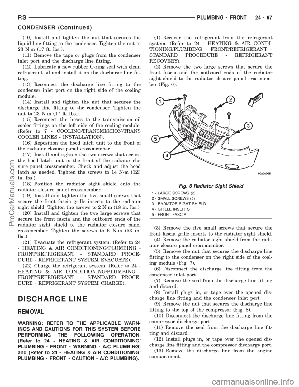
(2) Remove the two large screws that secure the
front fascia and the outboard ends of the radiator
sight shield to the radiator closure panel crossmem-
ber (Fig. 6).
(3) Remove the five small screws that secure the
front fascia grille inserts to the radiator sight shield.
(4) Remove the radiator sight shield from the radi-
ator closure panel crossmember.
(5) Remove the nut that secures the discharge line
fitting to the condenser on the right side of the cool-
ing module (Fig. 7).
(6) Disconnect the discharge line fitting from the
condenser inlet port.
(7) Remove the seal from the discharge line fitting
and discard.
(8) Install plugs in, or tape over the opened dis-
charge line fitting and the condenser inlet port.
(9) Remove the nut that secures the discharge line
fitting to the top of the compressor (Fig. 8).
(10) Disconnect the discharge line fitting from the
compressor discharge port.
(11) Remove the seal from the discharge line fit-
ting and discard.
(12) Install plugs in, or tape over the opened dis-
charge line fitting and the compressor discharge port.
(13) Remove the discharge line from the engine
compartment.
Fig. 6 Radiator Sight Shield
1 - LARGE SCREWS (2)
2 - SMALL SCREWS (5)
3 - RADIATOR SIGHT SHIELD
4 - GRILLE INSERTS
5 - FRONT FASCIA
RSPLUMBING - FRONT24-67
CONDENSER (Continued)
ProCarManuals.com