2002 CHRYSLER TOWN AND COUNTRY transmission removal
[x] Cancel search: transmission removalPage 1832 of 2399
SEAL - OIL PUMP
REMOVAL
(1) Remove transaxle from vehicle (Refer to 21 -
TRANSMISSION/TRANSAXLE/AUTOMATIC - 41TE
- REMOVAL).
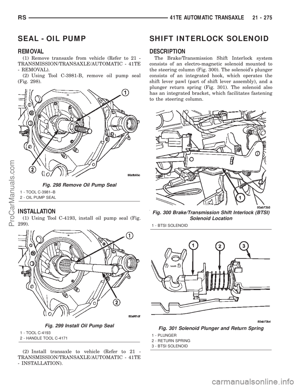
(2) Using Tool C-3981-B, remove oil pump seal
(Fig. 298).
INSTALLATION
(1) Using Tool C-4193, install oil pump seal (Fig.
299).
(2) Install transaxle to vehicle (Refer to 21 -
TRANSMISSION/TRANSAXLE/AUTOMATIC - 41TE
- INSTALLATION).
SHIFT INTERLOCK SOLENOID
DESCRIPTION
The Brake/Transmission Shift Interlock system
consists of an electro-magnetic solenoid mounted to
the steering column (Fig. 300). The solenoid's plunger
consists of an integrated hook, which operates the
shift lever pawl (part of shift lever assembly), and a
plunger return spring (Fig. 301). The solenoid also
has an integrated bracket, which facilitates fastening
to the steering column.
Fig. 298 Remove Oil Pump Seal
1 - TOOL C-3981±B
2 - OIL PUMP SEAL
Fig. 299 Install Oil Pump Seal
1 - TOOL C-4193
2 - HANDLE TOOL C-4171
Fig. 300 Brake/Transmission Shift Interlock (BTSI)
Solenoid Location
1 - BTSI SOLENOID
Fig. 301 Solenoid Plunger and Return Spring
1 - PLUNGER
2 - RETURN SPRING
3 - BTSI SOLENOID
RS41TE AUTOMATIC TRANSAXLE21 - 275
ProCarManuals.com
Page 1834 of 2399
A conventional mechanical interlock system is also
used. This system manually prohibits shifter move-
ment when the ignition switch is in the LOCK or
ACC positions. Solenoid operation is not required in
these key positions.
For intended BTSI system operation, refer to the
following chart:
ACTION EXPECTED RESPONSE
1. Turn key to the9OFF9
position.1. Shifter CAN be shifted
out of park with brake
pedal applied.
2. Turn key to the
9ON/RUN9position.2. Shifter CANNOT be
shifted out of park.
3. Turn key to the
9ON/RUN9position and
depress the brake pedal.3. Shifter CAN be shifted
out of park.
4. Leave shifter in any
gear and try to return key
to the9LOCK9or9ACC9
position.4. Key cannot be
returned to the9LOCK9or
9ACC9position.
5. Return shifter to
9PARK9and try to remove
the key.5. Key can be removed
(after returning to9LOCK9
position).
6. With the key removed,
try to shift out of9PARK9.6. Shifter cannot be
shifted out of9PARK9.
NOTE: Any failure to meet these expected
responses requires system adjustment or repair.
DIAGNOSIS AND TESTING - BRAKE/
TRANSMISSION SHIFT INTERLOCK SOLENOID
For intended BTSI system operation, refer to the
following chart:
ACTION EXPECTED RESPONSE
1. Turn key to the9OFF9
position.1. Shifter CAN be shifted
out of park with brake
pedal applied.
2. Turn key to the
9ON/RUN9position.2. Shifter CANNOT be
shifted out of park.
3. Turn key to the
9ON/RUN9position and
depress the brake pedal.3. Shifter CAN be shifted
out of park.
4. Leave shifter in any
gear and try to return key
to the9LOCK9or9ACC9
position.4. Key cannot be
returned to the9LOCK9or
9ACC9position.
5. Return shifter to
9PARK9and try to remove
the key.5. Key can be removed
(after returning to9LOCK9
position).
ACTION EXPECTED RESPONSE
6. With the key removed,
try to shift out of9PARK9.6. Shifter cannot be
shifted out of9PARK9.
NOTE: Any failure to meet these expected
responses requires system repair. Refer to the
appropriate Diagnostic Information.
REMOVAL
(1) Disconnect battery negative cable.
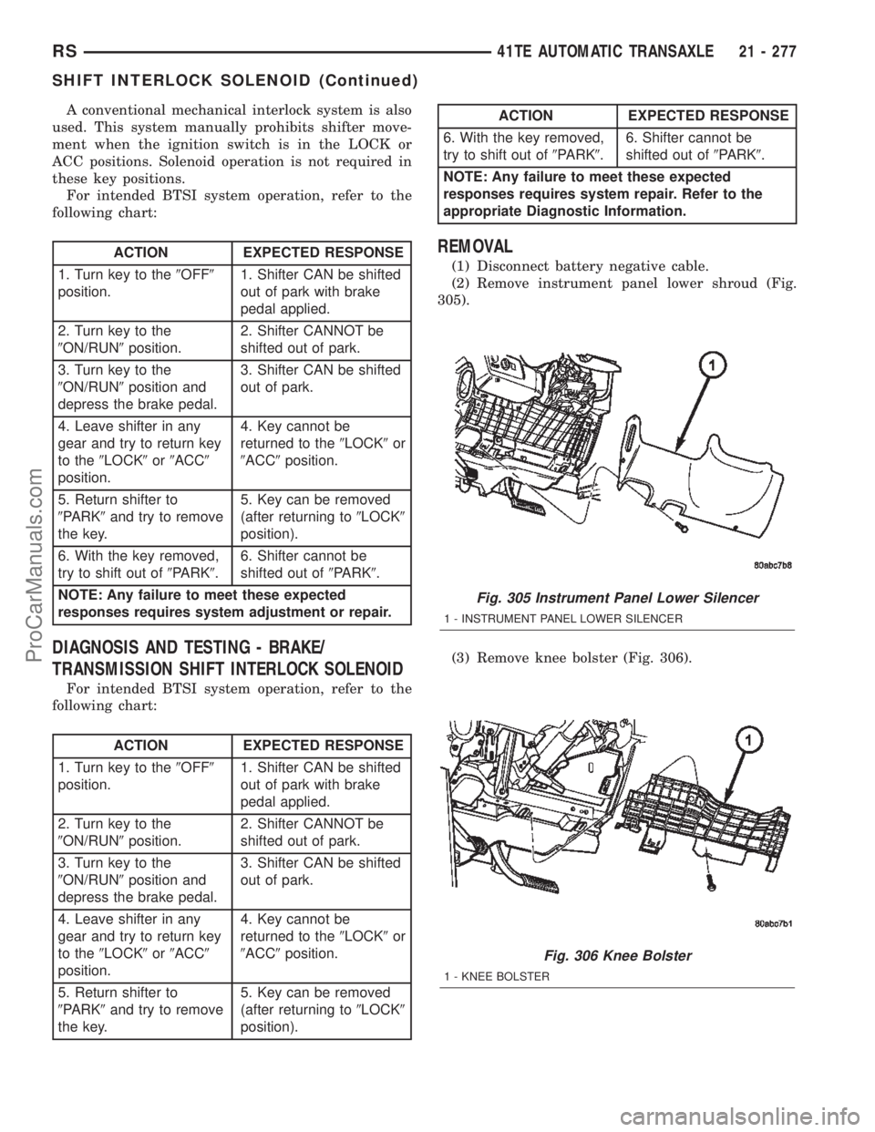
(2) Remove instrument panel lower shroud (Fig.
305).
(3) Remove knee bolster (Fig. 306).
Fig. 305 Instrument Panel Lower Silencer
1 - INSTRUMENT PANEL LOWER SILENCER
Fig. 306 Knee Bolster
1 - KNEE BOLSTER
RS41TE AUTOMATIC TRANSAXLE21 - 277
SHIFT INTERLOCK SOLENOID (Continued)
ProCarManuals.com
Page 1837 of 2399
OPERATION
SOLENOIDS
The solenoids receive electrical power from the
Transmission Control Relay through a single wire.
The TCM energizes or operates the solenoids individ-
ually by grounding the return wire of the solenoid
needed. When a solenoid is energized, the solenoid
valve shifts, and a fluid passage is opened or closed
(vented or applied), depending on its default operat-
ing state. The result is an apply or release of a fric-
tional element.
The 2/4 and UD solenoids are normally applied,
which by design allow fluid to pass through in their
relaxed or ªoffº state. This allows transaxle limp-in
(P,R,N,2) in the event of an electrical failure.
The continuity of the solenoids and circuits are
periodically tested. Each solenoid is turned on or off
depending on its current state. An inductive spike
should be detected by the TCM during this test. It no
spike is detected, the circuit is tested again to verify
the failure. In addition to the periodic testing, the
solenoid circuits are tested if a speed ratio or pres-
sure switch error occurs.
PRESSURE SWITCHES
The TCM relies on three pressure switches to mon-
itor fluid pressure in the L/R, 2/4, and OD hydraulic
circuits. The primary purpose of these switches is to
help the TCM detect when clutch circuit hydraulic
failures occur. The range for the pressure switch clos-
ing and opening points is 11-23 psi. Typically the
switch opening point will be approximately one psi
lower than the closing point. For example, a switch
may close at 18 psi and open at 17 psi. The switches
are continuously monitored by the TCM for the cor-
rect states (open or closed) in each gear as shown in
the following chart:
PRESSURE SWITCH STATES
GEAR L/R 2/4 OD
ROPOPOP
P/N CL OP OP
1st CL OP OP
2nd OP CL OP
DOPOPCL
OD OP CL CL
OP = OPEN
CL = CLOSED
A Diagnostic Trouble Code (DTC) will set if the
TCM senses any switch open or closed at the wrong
time in a given gear.The TCM also tests the 2/4 and OD pressure
switches when they are normally off (OD and 2/4 are
tested in 1st gear, OD in 2nd gear, and 2/4 in 3rd
gear). The test simply verifies that they are opera-
tional, by looking for a closed state when the corre-
sponding element is applied. Immediately after a
shift into 1st, 2nd, or 3rd gear with the engine speed
above 1000 rpm, the TCM momentarily turns on ele-
ment pressure to the 2/4 and/or OD clutch circuits to
identify that the appropriate switch has closed. If it
doesn't close, it is tested again. If the switch fails to
close the second time, the appropriate Diagnostic
Trouble Code (DTC) will set.
REMOVAL
NOTE: If solenoid/pressure switch assembly is
being replaced, it is necessary to perform the TCM
Quick Learn Procedure. (Refer to 8 - ELECTRICAL/
ELECTRONIC CONTROL MODULES/TRANSMISSION
CONTROL MODULE - STANDARD PROCEDURE)
(1) Disconnect battery negative cable.
(2) Remove air cleaner assembly.
(3) Disconnect solenoid/pressure switch assembly
connector.
(4) Disconnect input speed sensor connector.
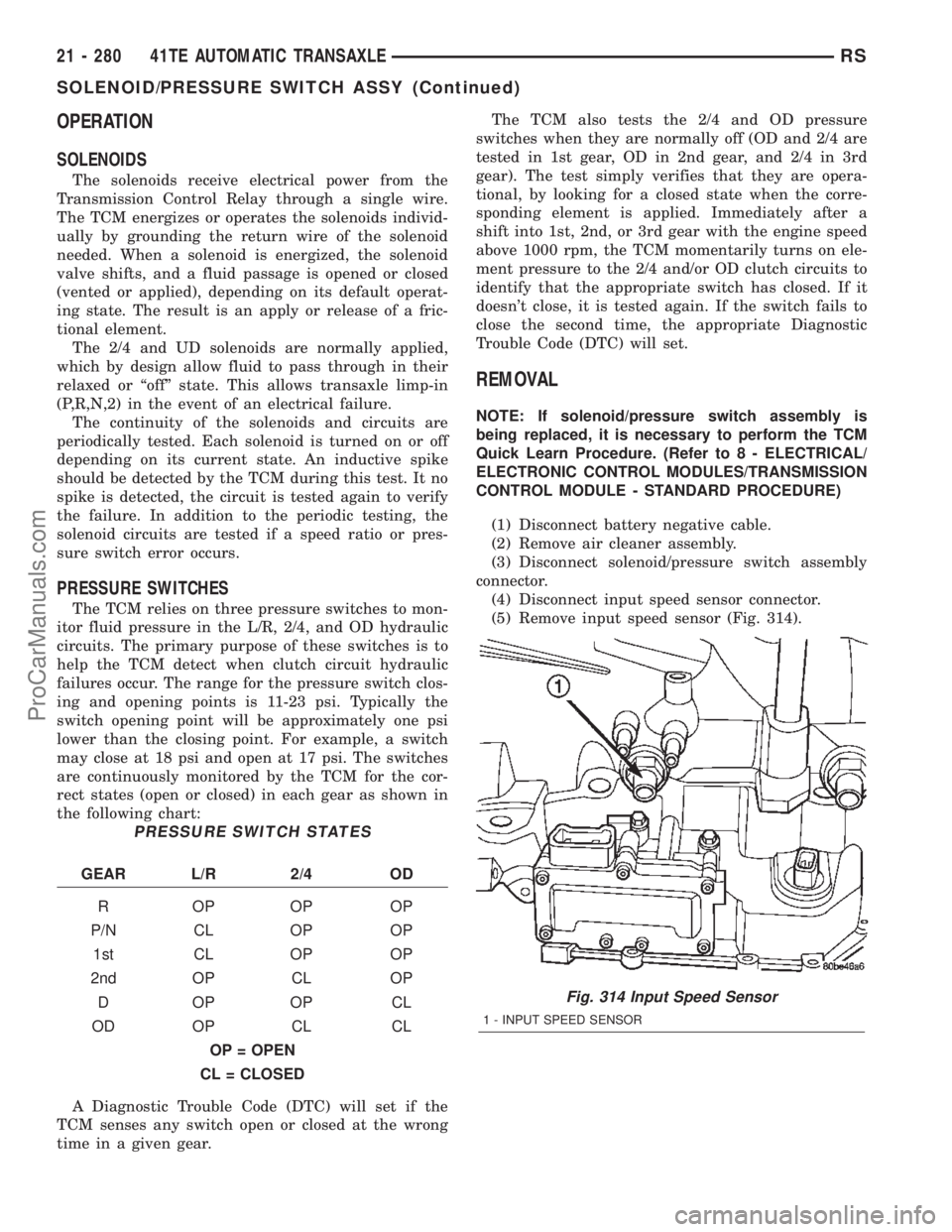
(5) Remove input speed sensor (Fig. 314).
Fig. 314 Input Speed Sensor
1 - INPUT SPEED SENSOR
21 - 280 41TE AUTOMATIC TRANSAXLERS
SOLENOID/PRESSURE SWITCH ASSY (Continued)
ProCarManuals.com
Page 1839 of 2399
OPERATION
The Input Speed Sensor provides information on
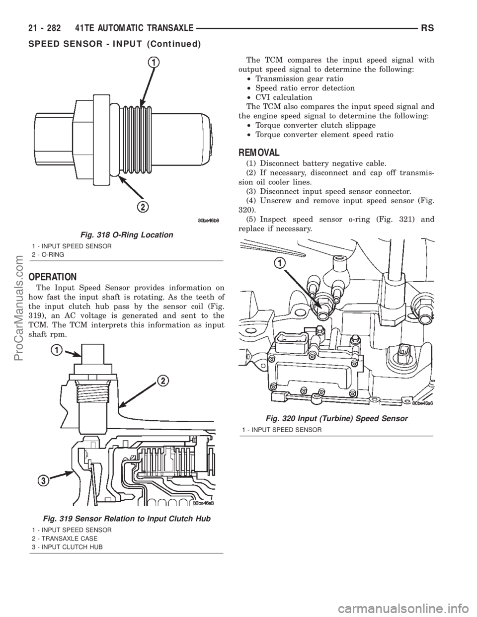
how fast the input shaft is rotating. As the teeth of
the input clutch hub pass by the sensor coil (Fig.
319), an AC voltage is generated and sent to the
TCM. The TCM interprets this information as input
shaft rpm.The TCM compares the input speed signal with
output speed signal to determine the following:
²Transmission gear ratio
²Speed ratio error detection
²CVI calculation
The TCM also compares the input speed signal and
the engine speed signal to determine the following:
²Torque converter clutch slippage
²Torque converter element speed ratio
REMOVAL
(1) Disconnect battery negative cable.
(2) If necessary, disconnect and cap off transmis-
sion oil cooler lines.
(3) Disconnect input speed sensor connector.
(4) Unscrew and remove input speed sensor (Fig.
320).
(5) Inspect speed sensor o-ring (Fig. 321) and
replace if necessary.
Fig. 318 O-Ring Location
1 - INPUT SPEED SENSOR
2 - O-RING
Fig. 319 Sensor Relation to Input Clutch Hub
1 - INPUT SPEED SENSOR
2 - TRANSAXLE CASE
3 - INPUT CLUTCH HUB
Fig. 320 Input (Turbine) Speed Sensor
1 - INPUT SPEED SENSOR
21 - 282 41TE AUTOMATIC TRANSAXLERS
SPEED SENSOR - INPUT (Continued)
ProCarManuals.com
Page 1847 of 2399
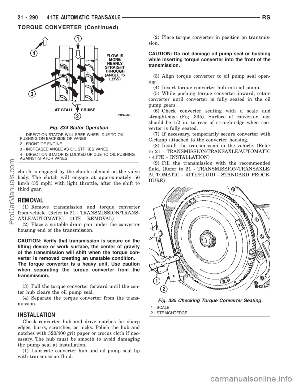
clutch is engaged by the clutch solenoid on the valve
body. The clutch will engage at approximately 56
km/h (35 mph) with light throttle, after the shift to
third gear.
REMOVAL
(1) Remove transmission and torque converter
from vehicle. (Refer to 21 - TRANSMISSION/TRANS-
AXLE/AUTOMATIC - 41TE - REMOVAL)
(2) Place a suitable drain pan under the converter
housing end of the transmission.
CAUTION: Verify that transmission is secure on the
lifting device or work surface, the center of gravity
of the transmission will shift when the torque con-
verter is removed creating an unstable condition.
The torque converter is a heavy unit. Use caution
when separating the torque converter from the
transmission.
(3) Pull the torque converter forward until the cen-
ter hub clears the oil pump seal.
(4) Separate the torque converter from the trans-
mission.
INSTALLATION
Check converter hub and drive notches for sharp
edges, burrs, scratches, or nicks. Polish the hub and
notches with 320/400 grit paper or crocus cloth if nec-
essary. The hub must be smooth to avoid damaging
the pump seal at installation.
(1) Lubricate converter hub and oil pump seal lip
with transmission fluid.(2) Place torque converter in position on transmis-
sion.
CAUTION: Do not damage oil pump seal or bushing
while inserting torque converter into the front of the
transmission.
(3) Align torque converter to oil pump seal open-
ing.
(4) Insert torque converter hub into oil pump.
(5) While pushing torque converter inward, rotate
converter until converter is fully seated in the oil
pump gears.
(6) Check converter seating with a scale and
straightedge (Fig. 335). Surface of converter lugs
should be 1/2 in. to rear of straightedge when con-
verter is fully seated.
(7) If necessary, temporarily secure converter with
C-clamp attached to the converter housing.
(8) Install the transmission in the vehicle. (Refer
to 21 - TRANSMISSION/TRANSAXLE/AUTOMATIC
- 41TE - INSTALLATION)
(9) Fill the transmission with the recommended
fluid. (Refer to 21 - TRANSMISSION/TRANSAXLE/
AUTOMATIC - 41TE/FLUID - STANDARD PROCE-
DURE)
Fig. 334 Stator Operation
1 - DIRECTION STATOR WILL FREE WHEEL DUE TO OIL
PUSHING ON BACKSIDE OF VANES
2 - FRONT OF ENGINE
3 - INCREASED ANGLE AS OIL STRIKES VANES
4 - DIRECTION STATOR IS LOCKED UP DUE TO OIL PUSHING
AGAINST STATOR VANES
Fig. 335 Checking Torque Converter Seating
1 - SCALE
2 - STRAIGHTEDGE
21 - 290 41TE AUTOMATIC TRANSAXLERS
TORQUE CONVERTER (Continued)
ProCarManuals.com
Page 1849 of 2399
OPERATION
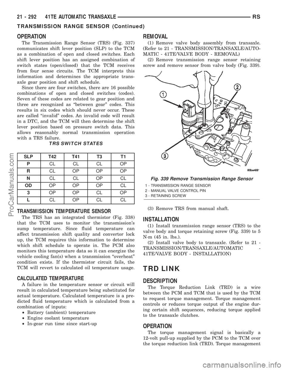
The Transmission Range Sensor (TRS) (Fig. 337)
communicates shift lever position (SLP) to the TCM
as a combination of open and closed switches. Each
shift lever position has an assigned combination of
switch states (open/closed) that the TCM receives
from four sense circuits. The TCM interprets this
information and determines the appropriate trans-
axle gear position and shift schedule.
Since there are four switches, there are 16 possible
combinations of open and closed switches (codes).
Seven of these codes are related to gear position and
three are recognized as ªbetween gearº codes. This
results in six codes which should never occur. These
are called ªinvalidº codes. An invalid code will result
in a DTC, and the TCM will then determine the shift
lever position based on pressure switch data. This
allows reasonably normal transmission operation
with a TRS failure.
TRS SWITCH STATES
SLP T42 T41 T3 T1
PCL CL CL OP
RCL OP OP OP
NCL CL OP CL
ODOP OP OP CL
3OP OP CL OP
LCL OP CL CL
TRANSMISSION TEMPERATURE SENSOR
The TRS has an integrated thermistor (Fig. 338)
that the TCM uses to monitor the transmission's
sump temperature. Since fluid temperature can
affect transmission shift quality and convertor lock
up, the TCM requires this information to determine
which shift schedule to operate in. The PCM also
monitors this temperature data so it can energize the
vehicle cooling fan(s) when a transmission ªoverheatº
condition exists. If the thermistor circuit fails, the
TCM will revert to calculated oil temperature usage.
CALCULATED TEMPERATURE
A failure in the temperature sensor or circuit will
result in calculated temperature being substituted for
actual temperature. Calculated temperature is a pre-
dicted fluid temperature which is calculated from a
combination of inputs:
²Battery (ambient) temperature
²Engine coolant temperature
²In-gear run time since start-up
REMOVAL
(1) Remove valve body assembly from transaxle.
(Refer to 21 - TRANSMISSION/TRANSAXLE/AUTO-
MATIC - 41TE/VALVE BODY - REMOVAL)
(2) Remove transmission range sensor retaining
screw and remove sensor from valve body (Fig. 339).
(3) Remove TRS from manual shaft.
INSTALLATION
(1) Install transmission range sensor (TRS) to the
valve body and torque retaining screw (Fig. 339) to 5
N´m (45 in. lbs.).
(2) Install valve body to transaxle. (Refer to 21 -
TRANSMISSION/TRANSAXLE/AUTOMATIC -
41TE/VALVE BODY - INSTALLATION)
TRD LINK
DESCRIPTION
The Torque Reduction Link (TRD) is a wire
between the PCM and TCM that is used by the TCM
to request torque management. Torque management
controls or reduces torque output of the engine dur-
ing certain shift sequences, reducing torque applied
to the transaxle clutches.
OPERATION
The torque management signal is basically a
12-volt pull-up supplied by the PCM to the TCM over
the torque reduction link (TRD). Torque management
Fig. 339 Remove Transmission Range Sensor
1 - TRANSMISSION RANGE SENSOR
2 - MANUAL VALVE CONTROL PIN
3 - RETAINING SCREW
21 - 292 41TE AUTOMATIC TRANSAXLERS
TRANSMISSION RANGE SENSOR (Continued)
ProCarManuals.com
Page 1851 of 2399
SOLENOID SWITCH VALVE
The solenoid switch valve controls line pressure
from the LR/CC solenoid. In one position, it allows
the low/reverse clutch to be pressurized. In the other,
it directs line pressure to the converter control and
converter clutch valves.
MANUAL VALVE
The manual valve is operated by the mechanical
shift linkage. Its primary responsibility is to send
line pressure to the appropriate hydraulic circuits
and solenoids. The valve has three operating ranges
or positions.
CONVERTER CLUTCH SWITCH VALVE
The main responsibility of the converter clutch switch
valve is to control hydraulic pressure applied to the front
(off) side of the converter clutch piston. Line pressure
from the regulator valve is fed to the torque converter
regulator valve, where it passes through the valve, and is
slightly regulated. The pressure is then directed to the
converter clutch switch valve and to the front side of the
converter clutch piston. This pressure pushes the piston
back and disengages the converter clutch.
CONVERTER CLUTCH CONTROL VALVE
The converter clutch control valve controls the
back (on) side of the torque converter clutch. When
the TCM energizes or modulates the LR/CC solenoid
to apply the converter clutch piston, both the con-
verter clutch control valve and the converter control
valve move, allowing pressure to be applied to the
back side of the clutch.
T/C REGULATOR VALVE
The torque converter regulator valve slightly regu-
lates the flow of fluid to the torque converter.
LOW/REVERSE SWITCH VALVE
The low/reverse clutch is applied from different
sources, depending on whether low (1st) gear or
reverse is selected. The low/reverse switch valve
alternates positions depending on from which direc-
tion fluid pressure is applied. By design, when the
valve is shifted by fluid pressure from one channel,
the opposing channel is blocked. The switch valve
alienates the possibility of a sticking ball check, thus
providing consistent application of the low/reverse
clutch under all operating conditions.
REMOVAL
REMOVAL
NOTE: If valve body is replaced or reconditioned,
the TCM Quick Learn Procedure must be per-formed. (Refer to 8 - ELECTRICAL/ELECTRONIC
CONTROL MODULES/TRANSMISSION CONTROL
MODULE - STANDARD PROCEDURE)
(1) Disconnect battery negative cable.
(2) Disconnect gearshift cable from manual valve
lever.
(3) Remove manual valve lever from manual shaft.
(4) Raise vehicle on hoist.
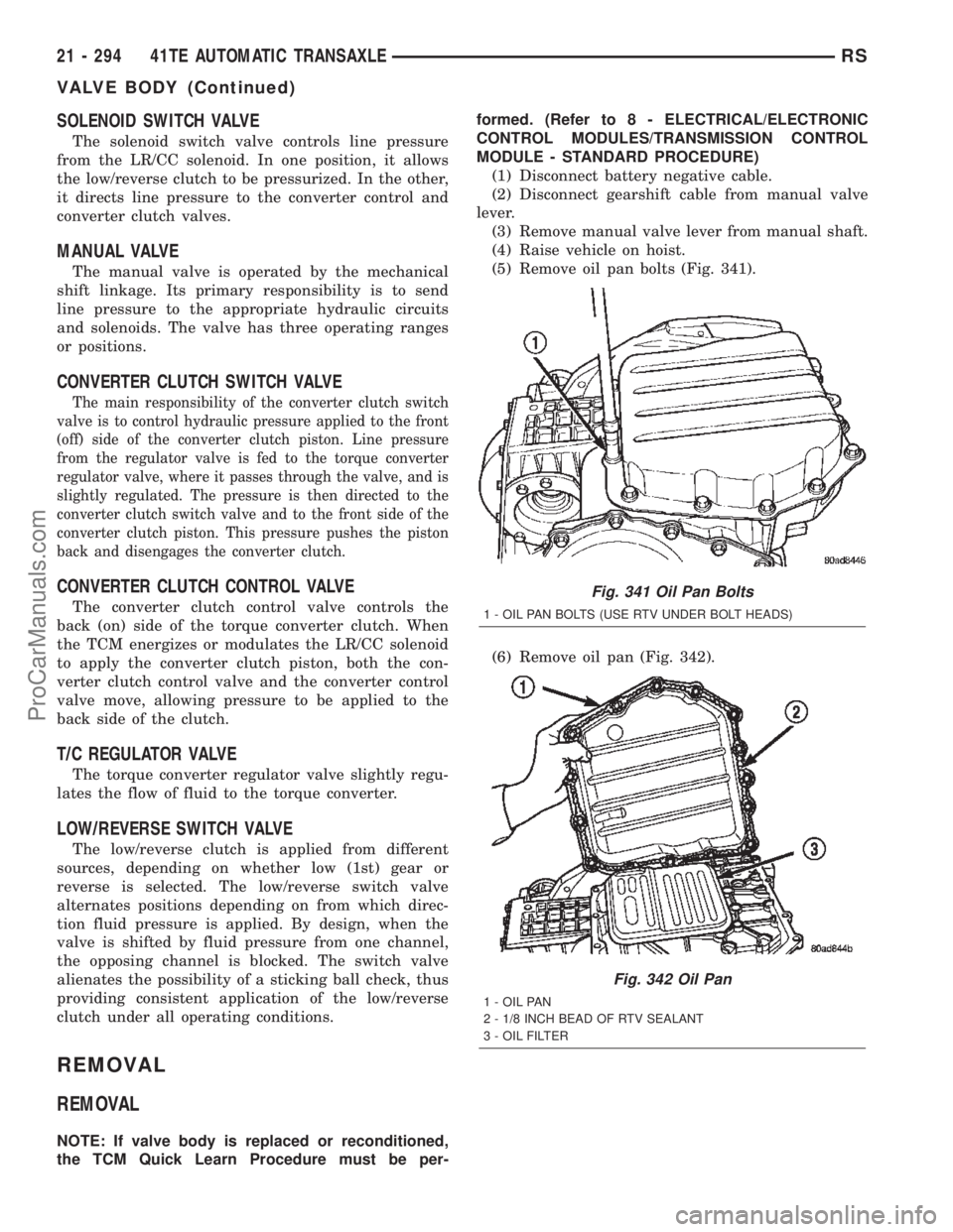
(5) Remove oil pan bolts (Fig. 341).
(6) Remove oil pan (Fig. 342).
Fig. 341 Oil Pan Bolts
1 - OIL PAN BOLTS (USE RTV UNDER BOLT HEADS)
Fig. 342 Oil Pan
1 - OIL PAN
2 - 1/8 INCH BEAD OF RTV SEALANT
3 - OIL FILTER
21 - 294 41TE AUTOMATIC TRANSAXLERS
VALVE BODY (Continued)
ProCarManuals.com
Page 1853 of 2399
REMOVAL
NOTE: If valve body is replaced or reconditioned,
the TCM Quick Learn Procedure must be per-
formed. (Refer to 8 - ELECTRICAL/ELECTRONIC
CONTROL MODULES/TRANSMISSION CONTROL
MODULE - STANDARD PROCEDURE)
(1) Disconnect battery negative cable.
(2) Disconnect gearshift cable from manual valve
lever.
(3) Remove manual valve lever from manual shaft.
(4) Raise vehicle on hoist.
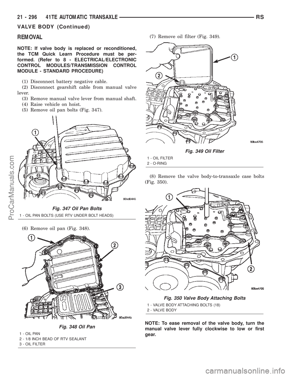
(5) Remove oil pan bolts (Fig. 347).
(6) Remove oil pan (Fig. 348).(7) Remove oil filter (Fig. 349).
(8) Remove the valve body-to-transaxle case bolts
(Fig. 350).
NOTE: To ease removal of the valve body, turn the
manual valve lever fully clockwise to low or first
gear.
Fig. 347 Oil Pan Bolts
1 - OIL PAN BOLTS (USE RTV UNDER BOLT HEADS)
Fig. 348 Oil Pan
1 - OIL PAN
2 - 1/8 INCH BEAD OF RTV SEALANT
3 - OIL FILTER
Fig. 349 Oil Filter
1 - OIL FILTER
2 - O-RING
Fig. 350 Valve Body Attaching Bolts
1 - VALVE BODY ATTACHING BOLTS (18)
2 - VALVE BODY
21 - 296 41TE AUTOMATIC TRANSAXLERS
VALVE BODY (Continued)
ProCarManuals.com