2002 CHRYSLER TOWN AND COUNTRY transmission removal
[x] Cancel search: transmission removalPage 488 of 2399

INSTRUMENT CLUSTER
TABLE OF CONTENTS
page page
INSTRUMENT CLUSTER
DESCRIPTION..........................1
OPERATION............................1
DIAGNOSIS AND TESTING
DIAGNOSIS AND TESTING - SELF-
DIAGNOSTICS.........................2
DIAGNOSIS AND TESTING - CLUSTER
DIAGNOSIS...........................2
REMOVAL.............................11
INSTALLATION.........................12CLUSTER LENS
REMOVAL.............................12
INSTALLATION.........................12
MECHANICAL TRANSMISSION RANGE
INDICATOR
REMOVAL.............................12
INSTALLATION.........................12
RED BRAKE WARNING INDICATOR
DESCRIPTION.........................13
OPERATION...........................13
INSTRUMENT CLUSTER
DESCRIPTION
The instrumentation gauges are contained in a
subdial assembly within the instrument cluster. The
individual gauges are not serviceable. If one of the
cluster gauges becomes faulty, the entire cluster
would require replacement.
The mechanical instrument cluster with a tachom-
eter is equipped with a electronic vacuum fluorescent
transmission range indicator (PRND3L), odometer,
and trip odometer display.
The mechanical instrument cluster without a
tachometer is equipped with a cable operated trans-
mission range indicator (PRND21) and a vacuum flu-
orescent odometer display. It also has the following
indicators:
²Turn Signals
²High Beam
²Oil Pressure
²MIL
The instrument cluster is equipped with the follow-
ing warning lamps.
²Lift Gate Ajar
²Low Fuel Level
²Low Windshield Washer Fluid Level
²Cruise
²Battery Voltage
²Fasten Seat Belt
²Door Ajar
²Coolant Temperature
²Anti-Lock Brake
²Brake
²Airbag
²Traction Control
²AutostickThe mechanical instrument cluster without a
tachometer also has the following warning lamps:
²Turns Signals
²High Beam
²Oil Pressure
²Malfunction Indicator Lamp (MIL)
WATER IN FUEL LAMP - EXPORT
The Water In Fuel Lamp is located in the instru-
ment cluster. When moisture is found within the fuel
system, the sensor sends a message via the PCI data
bus to the instrument cluster. The sensor is located
underneath the vehicle, directly above the rear axle.
The sensor is housed within the fuel filter/water sep-
arator assembly cover. The sensor is not serviced sep-
arately. If found defective, the entire assembly cover
must be replaced.
OPERATION
Refer to the vehicle Owner's Manual for operation
instructions and conditions for the Instrument Clus-
ter Gauges.
WATER IN FUEL LAMP - EXPORT
The Water In Fuel Sensor is a resistive type
switch. It is calibrated to sense the different resis-
tance between diesel fuel and water. When water
enters the fuel system, it is caught in the bottom of
the fuel filter/water separator assembly, where the
sensor is located. Water has less resistance than die-
sel fuel. The sensor then sends a PCI data bus mes-
sage to the instrument cluster to illuminate the
lamp.
If the lamp is inoperative, perform the self diag-
nostic test on the instrument cluster to check the
lamp operation before continuing diagnosis.
RSINSTRUMENT CLUSTER8J-1
ProCarManuals.com
Page 498 of 2399
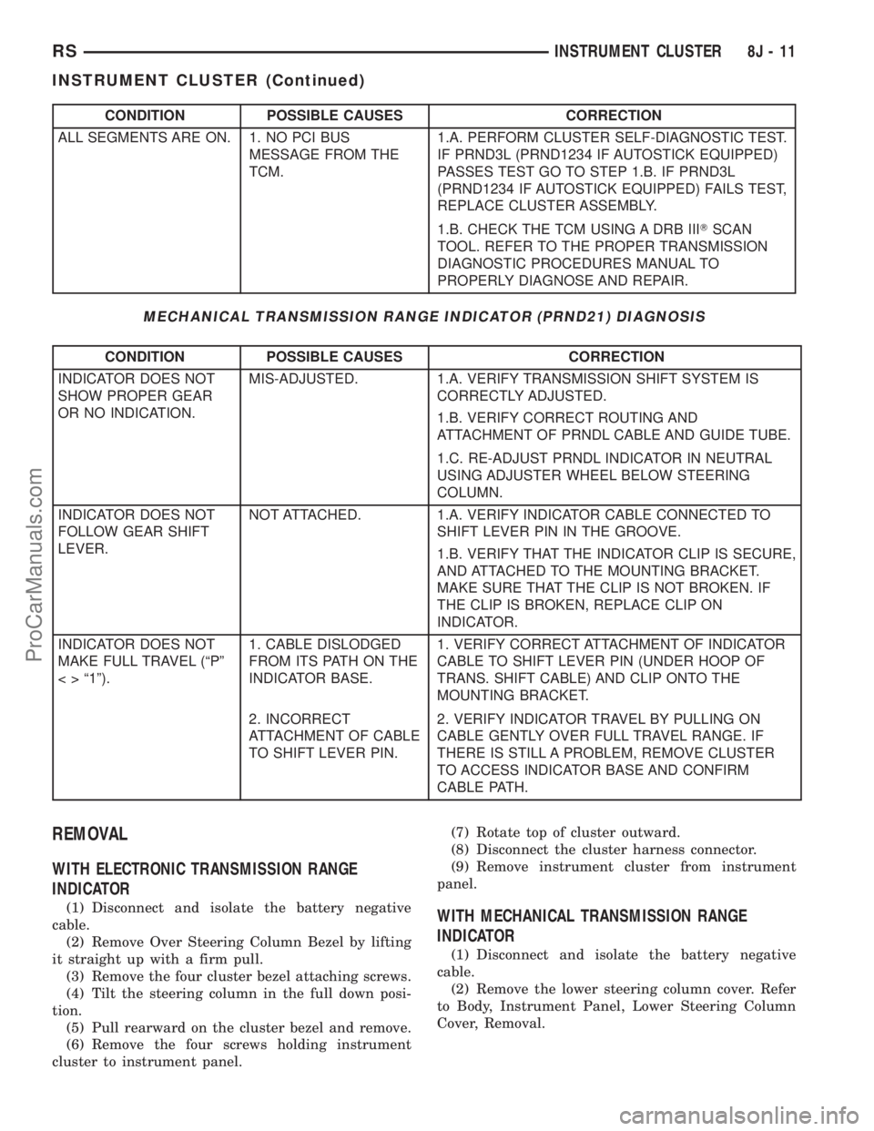
CONDITION POSSIBLE CAUSES CORRECTION
ALL SEGMENTS ARE ON. 1. NO PCI BUS
MESSAGE FROM THE
TCM.1.A. PERFORM CLUSTER SELF-DIAGNOSTIC TEST.
IF PRND3L (PRND1234 IF AUTOSTICK EQUIPPED)
PASSES TEST GO TO STEP 1.B. IF PRND3L
(PRND1234 IF AUTOSTICK EQUIPPED) FAILS TEST,
REPLACE CLUSTER ASSEMBLY.
1.B. CHECK THE TCM USING A DRB IIITSCAN
TOOL. REFER TO THE PROPER TRANSMISSION
DIAGNOSTIC PROCEDURES MANUAL TO
PROPERLY DIAGNOSE AND REPAIR.
MECHANICAL TRANSMISSION RANGE INDICATOR (PRND21) DIAGNOSIS
CONDITION POSSIBLE CAUSES CORRECTION
INDICATOR DOES NOT
SHOW PROPER GEAR
OR NO INDICATION.MIS-ADJUSTED. 1.A. VERIFY TRANSMISSION SHIFT SYSTEM IS
CORRECTLY ADJUSTED.
1.B. VERIFY CORRECT ROUTING AND
ATTACHMENT OF PRNDL CABLE AND GUIDE TUBE.
1.C. RE-ADJUST PRNDL INDICATOR IN NEUTRAL
USING ADJUSTER WHEEL BELOW STEERING
COLUMN.
INDICATOR DOES NOT
FOLLOW GEAR SHIFT
LEVER.NOT ATTACHED. 1.A. VERIFY INDICATOR CABLE CONNECTED TO
SHIFT LEVER PIN IN THE GROOVE.
1.B. VERIFY THAT THE INDICATOR CLIP IS SECURE,
AND ATTACHED TO THE MOUNTING BRACKET.
MAKE SURE THAT THE CLIP IS NOT BROKEN. IF
THE CLIP IS BROKEN, REPLACE CLIP ON
INDICATOR.
INDICATOR DOES NOT
MAKE FULL TRAVEL (ªPº
< > ª1º).1. CABLE DISLODGED
FROM ITS PATH ON THE
INDICATOR BASE.1. VERIFY CORRECT ATTACHMENT OF INDICATOR
CABLE TO SHIFT LEVER PIN (UNDER HOOP OF
TRANS. SHIFT CABLE) AND CLIP ONTO THE
MOUNTING BRACKET.
2. INCORRECT
ATTACHMENT OF CABLE
TO SHIFT LEVER PIN.2. VERIFY INDICATOR TRAVEL BY PULLING ON
CABLE GENTLY OVER FULL TRAVEL RANGE. IF
THERE IS STILL A PROBLEM, REMOVE CLUSTER
TO ACCESS INDICATOR BASE AND CONFIRM
CABLE PATH.
REMOVAL
WITH ELECTRONIC TRANSMISSION RANGE
INDICATOR
(1) Disconnect and isolate the battery negative
cable.
(2) Remove Over Steering Column Bezel by lifting
it straight up with a firm pull.
(3) Remove the four cluster bezel attaching screws.
(4) Tilt the steering column in the full down posi-
tion.
(5) Pull rearward on the cluster bezel and remove.
(6) Remove the four screws holding instrument
cluster to instrument panel.(7) Rotate top of cluster outward.
(8) Disconnect the cluster harness connector.
(9) Remove instrument cluster from instrument
panel.WITH MECHANICAL TRANSMISSION RANGE
INDICATOR
(1) Disconnect and isolate the battery negative
cable.
(2) Remove the lower steering column cover. Refer
to Body, Instrument Panel, Lower Steering Column
Cover, Removal.
RSINSTRUMENT CLUSTER8J-11
INSTRUMENT CLUSTER (Continued)
ProCarManuals.com
Page 499 of 2399
(3) Remove the plastic knee blocker reinforcement.
Refer to Body, Instrument Panel, Knee Blocker Rein-
forcement, Removal.
(4) Disconnect the transmission range indicator
cable end from shift lever by flexing the HOOP on
the transmission shift cable rearward and slip the
indicator cable loop off the lever pin.
(5) Disconnect the clip holding the indicator cable
to the mounting bracket.
(6) Remove Over Steering Column Bezel by lifting
it straight up with a firm pull.
(7) Remove the four bezel attaching screws.
(8) Tilt the steering column in the full down posi-
tion.
(9) Pull rearward on the cluster bezel and remove.
(10) Remove the four cluster attaching screws.
(11) Rotate top of the cluster rearward.
(12) Disconnect the cluster harness connector.
(13) Remove the instrument cluster carefully while
guiding the range indicator cable and guide tube
through the opening to avoid any damage.
INSTALLATION
WITH ELECTRONIC TRANSMISSION RANGE
INDICATOR
(1) Connect the instrument cluster wire connector.
(2) Rotate top of cluster inward as placing into
instrument panel opening.
(3) Install the four screws holding instrument clus-
ter to instrument panel.
(4) Position cluster bezel into place.
(5) Install the four bezel attaching screws.
(6) Install the Over Steering Column Bezel by
firmly snapping into place.
(7) Connect the battery negative cable.
WITH MECHANICAL TRANSMISSION RANGE
INDICATOR
(1) Guide the range indicator cable and guide tube
through the opening of instrument panel.
(2) Connect the instrument cluster wire connector.
(3) Rotate top of cluster inward as placing into
instrument panel opening.
(4) Install the four screws holding instrument clus-
ter to instrument panel.
(5) Position cluster bezel into place.
(6) Install the four bezel attaching screws.
(7) Install the Over Steering Column Bezel by
firmly snapping into place.
(8) Connect the clip holding the indicator cable to
the mounting bracket.(9) Connect the transmission range indicator cable
end to the shift lever by flexing the HOOP on the
transmission shift cable forward and slip the indica-
tor cable loop on the lever pin.
(10) Install the plastic knee blocker reinforcement.
Refer to Body, Instrument Panel, Knee Blocker Rein-
forcement, Installation.
(11) Install the lower steering column cover. Refer
to Body, Instrument Panel, Lower Steering Column
Cover, Installation.
(12) Connect the battery negative cable.
CLUSTER LENS
REMOVAL
(1) Remove the instrument cluster. Refer to Elec-
trical, Instrument Cluster, Removal.
(2) Remove the screws holding the lens to the
instrument cluster.
(3) Press down on the snap features of the lens
and remove the lens from the cluster.
INSTALLATION
(1) Insert the lens snap features into the cluster.
(2) Install the screws holding the lens to the
instrument cluster.
(3) Install the instrument cluster. Refer to Electri-
cal, Instrument Cluster, Installation.
MECHANICAL TRANSMISSION
RANGE INDICATOR
REMOVAL
(1) Remove the instrument cluster and disconnect
the range indicator cable at both attaching points.
Refer to Electrical, Instrument Cluster, Removal.
(2) From the backside of the cluster, remove two
screws holding the mechanical transmission range
indicator and then remove it fromt instrument clus-
ter.
INSTALLATION
(1) Insert the mechanical transmission range indi-
cator into the backside of the instrument cluster and
install the two screws.
(2) Install the instrument cluster. Refer to Electri-
cal, Instrument Cluster, Installation.
8J - 12 INSTRUMENT CLUSTERRS
INSTRUMENT CLUSTER (Continued)
ProCarManuals.com
Page 580 of 2399
POWER LOCKS
TABLE OF CONTENTS
page page
POWER LOCKS
DESCRIPTION.........................39
OPERATION...........................40
DOOR CYLINDER LOCK SWITCH
DESCRIPTION.........................41
OPERATION...........................41
DIAGNOSIS AND TESTING - DOOR
CYLINDER LOCK SWITCH..............41
REMOVAL.............................42
INSTALLATION.........................42
DOOR LOCK MOTOR
DIAGNOSIS AND TESTING - DOOR LOCK
MOTOR .............................42
DOOR LOCK SWITCH
DIAGNOSIS AND TESTING - DOOR LOCK
SWITCH............................42
REMOVAL.............................43
INSTALLATION.........................43
KEYLESS ENTRY TRANSMITTER
STANDARD PROCEDURE
STANDARD PROCEDURE - HORN CHIRP
PREFERENCE........................43STANDARD PROCEDURE - BATTERY
REPLACEMENT.......................43
SPECIFICATIONS
RANGE.............................43
BATTERY...........................43
REMOTE KEYLESS ENTRY MODULE
DESCRIPTION.........................44
OPERATION...........................44
DIAGNOSIS AND TESTING - REMOTE
KEYLESS ENTRY MODULE..............44
STANDARD PROCEDURE - PROGRAMMING
RKE MODULE........................44
REMOVAL.............................44
INSTALLATION.........................45
SLIDING DOOR LOCK MOTOR
REMOVAL.............................45
INSTALLATION.........................45
POWER LOCKS
DESCRIPTION
POWER DOOR LOCK SYSTEM
The front doors, sliding door(s) and liftgate are
equipped with actuator motors to lock or unlock the
latch mechanisms. The door lock actuator motor is
not serviced separately from the door latch, except
for the sliding door(s).
AUTOMATIC DOOR LOCK
The vehicle comes with two options for power door
locks:
²Rolling automatic lock (ENABLE), doors auto-
matically lock at approximately at 25.7 Km/h (16
mph).
²No rolling automatic lock (DISABLE), doors do
not automatically lock when the vehicle is moving.
AUTOMATIC DOOR UNLOCK
The doors will unlock automatically on vehicles
equipped with power door locks if:
²Auto door locks feature is enabled and automatic
unlock is enabled.²The transmission was in gear and speed is above
zero.
²The transmission in park or neutral and speed
is zero.
²Any door (excluding liftgate) opens.
DOOR LOCK INHIBIT
The BCM cancels out the door lock switch actua-
tion, when the key is in the Ignition Switch and
either front door is open.
Pressing the key fob RKE lock/unlock under these
conditions results in normal lock/unlock activation.
CENTRAL LOCKING
If equipped with Vehicle Theft Security System
(VTSS), all the doors can be locked with the key by
using any of the door lock cylinders. Turning the key
to the lock position will lock all the doors.
DOOR LOCK CIRCUIT PROTECTION
The door lock system is protected by a 40 amp fuse
located in the IPM. The BCM receives lock/unlock
input and will turn on the appropriate drivers and
provide a voltage level to the door lock motor for a
specific time. The IPM is located along the side of the
vehicle battery in the engine compartment.
RSPOWER LOCKS8N-39
ProCarManuals.com
Page 600 of 2399
(7) Remove the power seat switch from the out-
board seat cushion side shield.
INSTALLATION
(1) Position the power seat switch onto the out-
board seat cushion side shield.
(2) Install and tighten the screws that secure the
power seat switch to the inside of the outboard seat
cushion side shield. Tighten the screws to 1.5 N´m
(14 in. lbs.).
(3) Reconnect the power seat wire harness connec-
tor to the power seat switch connector receptacle.
(4) Position the outboard seat cushion side shield
onto the seat cushion frame
(5) Install and tighten the screws that secure the
outboard seat cushion side shield to the seat cushion
frame. Tighten the screws to 1.5 N´m (14 in. lbs.).
(6) Install the switch knobs on the switch control
levers, if equipped.
(7) Reconnect the battery negative cable.
MEMORY MIRROR/SEAT
MODULE
DESCRIPTION
Vehicles equipped with the memory mirror/seat
option, utilize a memory module located under the
drivers front seat. This module is basically wired in-
line between the power seat switch and the power
seat track/adjuster motors, or in-line between the
power mirror switch and the power side view mirror.
The MSMM contains a central processing unit that
communicates with other modules on the Program-
mable Communications Interface (PCI) data bus net-
work.
The Memory Seat/Mirror Module (MSMM) receives
hard wired inputs from the driver power seat switch
and the potentiometers on each of the driver side
power seat track motors, or from the power mirror
switch and the potentiometers on the side view mir-
ror. The MSMM receives messages over the PCI data
bus from the Body Control Module (BCM) (memory
switch status), the Powertrain Control Module (PCM)
(vehicle speed status). The MSMM will prevent the
seat memory recall function from being initiated if
the driver side seat belt is buckled, if the transmis-
sion gear selector lever is not in the Park or Neutral
positions, or if the vehicle is moving.
For diagnosis of the MSMM or the PCI data bus, a
DRBIIItscan tool and the proper Diagnostic Proce-
dures manual are recommended. The MSMM cannot
be repaired and, if faulty or damaged, it must be
replaced. Refer toMemory Systemin the Power
Seat or Power Mirror section of this manual for more
information on the memory system option.
OPERATION
When memory system operation is requested
(depressing of the memory switch), a resistor multi-
plexed signal is sent from the memory switch to the
body control module (BCM). The body control module
will then send the appropriate signals out to the
memory/mirror seat module, the memory/mirror seat
module then applies the voltage supply to the power
seat track or side-view mirror if the proper require-
ments are met. The vehicle speed must equal zero
and the transmission must be in park or neutral in
order for the memory system to function.
DIAGNOSIS AND TESTING - MEMORY
MIRROR/SEAT MODULE
Visually inspect the related wiring harness connec-
tors. Look for broken, bent, pushed out, or corroded
terminals. If any of the above conditions are present,
repair as necessary. If not, use a DRB IIItscan tool
and the proper Diagnostic Procedures Manual to test
the memory/mirror seat module. For complete circuit
diagrams, refer toWiring Diagrams.
REMOVAL
(1) Disconnect and isolate the battery negative
cable.
(2) Remove the driver side front bucket seat
retaining nuts from under the vehicle (Refer to 23 -
BODY/SEATS/SEAT - REMOVAL).
(3) Lift the drivers seat up and out of the mount-
ing holes in the floor pan and lay the seat rearward
to access the module located under the seat. It is not
necessary to disconnect the seat electrical, just use
care not to damage the wiring by over-extending.
(4) Disconnect the memory/mirror seat module
electrical connectors. Depress the retaining tab and
pull straight apart.
(5) Remove the module retaining bolts and remove
the module from the bracket.
INSTALLATION
(1) Position and install the module retaining bolts.
(2) Connect the memory/mirror seat module elec-
trical connectors.
(3) Position the drivers seat in the mounting holes
in the floor pan.
(4) Install the driver side front bucket seat retain-
ing nuts from under the vehicle (Refer to 23 - BODY/
SEATS/SEAT - INSTALLATION).
(5) Connect the battery negative cable.
RSPOWER SEAT SYSTEM8N-59
PASSENGER SEAT SWITCH (Continued)
ProCarManuals.com
Page 626 of 2399
SPEED CONTROL
TABLE OF CONTENTS
page page
SPEED CONTROL
DESCRIPTION..........................1
OPERATION
OPERATION..........................1
OPERATION - INTERACTIVE SPEED
CONTROL (4 Speed EATX Only)...........2
DIAGNOSIS AND TESTING - ROAD TEST.....3
SPECIFICATIONS - TORQUE...............3
CABLE
DESCRIPTION..........................4
OPERATION............................4
REMOVAL.............................4
INSTALLATION..........................4
SERVO
DESCRIPTION..........................4OPERATION............................4
REMOVAL.............................4
INSTALLATION..........................5
SWITCH
DESCRIPTION..........................5
OPERATION............................5
REMOVAL.............................5
INSTALLATION..........................6
VACUUM RESERVOIR
DESCRIPTION..........................6
OPERATION............................6
REMOVAL.............................6
INSTALLATION..........................6
SPEED CONTROL
DESCRIPTION
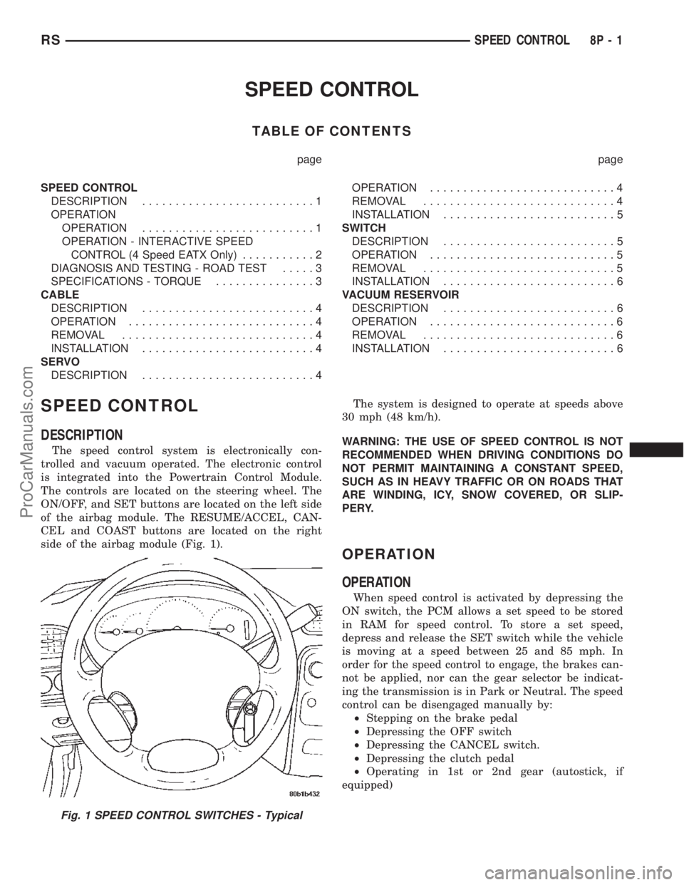
The speed control system is electronically con-
trolled and vacuum operated. The electronic control
is integrated into the Powertrain Control Module.
The controls are located on the steering wheel. The
ON/OFF, and SET buttons are located on the left side
of the airbag module. The RESUME/ACCEL, CAN-
CEL and COAST buttons are located on the right
side of the airbag module (Fig. 1).The system is designed to operate at speeds above
30 mph (48 km/h).
WARNING: THE USE OF SPEED CONTROL IS NOT
RECOMMENDED WHEN DRIVING CONDITIONS DO
NOT PERMIT MAINTAINING A CONSTANT SPEED,
SUCH AS IN HEAVY TRAFFIC OR ON ROADS THAT
ARE WINDING, ICY, SNOW COVERED, OR SLIP-
PERY.
OPERATION
OPERATION
When speed control is activated by depressing the
ON switch, the PCM allows a set speed to be stored
in RAM for speed control. To store a set speed,
depress and release the SET switch while the vehicle
is moving at a speed between 25 and 85 mph. In
order for the speed control to engage, the brakes can-
not be applied, nor can the gear selector be indicat-
ing the transmission is in Park or Neutral. The speed
control can be disengaged manually by:
²Stepping on the brake pedal
²Depressing the OFF switch
²Depressing the CANCEL switch.
²Depressing the clutch pedal
²Operating in 1st or 2nd gear (autostick, if
equipped)
Fig. 1 SPEED CONTROL SWITCHES - Typical
RSSPEED CONTROL8P-1
ProCarManuals.com
Page 1214 of 2399
NOTE: When the transaxle cooler lines are removed
from the rolled-groove type fittings at the transaxle,
damage to the inner wall of the hose will occur. To
prevent prevent potential leakage, the cooler hoses
must be cut off flush at the transaxle fitting, and a
service cooler hose splice kit must be installed
upon reassembly.
(9) Using a blade or suitable hose cutter, cut trans-
axle oil cooler lines off flush with fittings. Plug cooler
lines and fittings to prevent debris from entering
transaxle or cooler circuit. A service splice kit will be
installed upon reassembly.
(10) Disconnect transmission shift linkage and
electrical connectors.
(11) Disconnect throttle body linkage.
(12) Disconnect engine wiring harness.
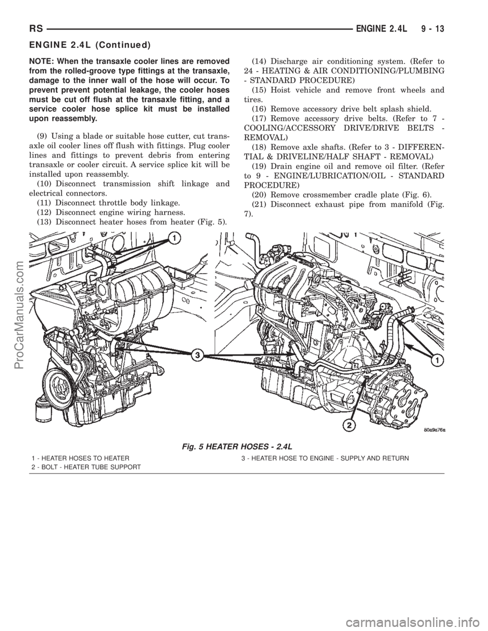
(13) Disconnect heater hoses from heater (Fig. 5).(14) Discharge air conditioning system. (Refer to
24 - HEATING & AIR CONDITIONING/PLUMBING
- STANDARD PROCEDURE)
(15) Hoist vehicle and remove front wheels and
tires.
(16) Remove accessory drive belt splash shield.
(17) Remove accessory drive belts. (Refer to 7 -
COOLING/ACCESSORY DRIVE/DRIVE BELTS -
REMOVAL)
(18) Remove axle shafts. (Refer to 3 - DIFFEREN-
TIAL & DRIVELINE/HALF SHAFT - REMOVAL)
(19) Drain engine oil and remove oil filter. (Refer
to 9 - ENGINE/LUBRICATION/OIL - STANDARD
PROCEDURE)
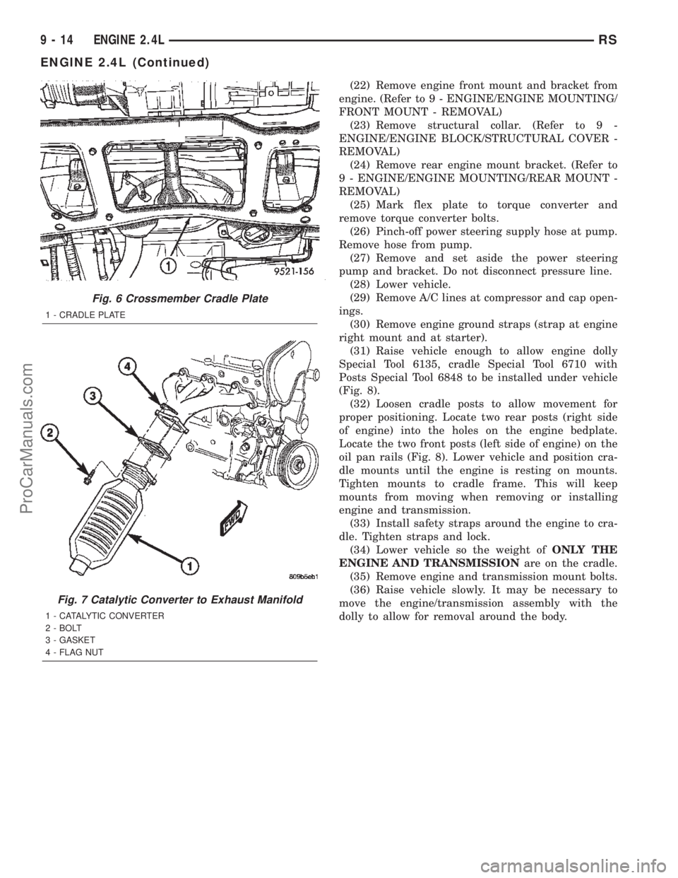
(20) Remove crossmember cradle plate (Fig. 6).
(21) Disconnect exhaust pipe from manifold (Fig.
7).
Fig. 5 HEATER HOSES - 2.4L
1 - HEATER HOSES TO HEATER 3 - HEATER HOSE TO ENGINE - SUPPLY AND RETURN
2 - BOLT - HEATER TUBE SUPPORT
RSENGINE 2.4L9-13
ENGINE 2.4L (Continued)
ProCarManuals.com
Page 1215 of 2399
(22) Remove engine front mount and bracket from
engine. (Refer to 9 - ENGINE/ENGINE MOUNTING/
FRONT MOUNT - REMOVAL)
(23) Remove structural collar. (Refer to 9 -
ENGINE/ENGINE BLOCK/STRUCTURAL COVER -
REMOVAL)
(24) Remove rear engine mount bracket. (Refer to
9 - ENGINE/ENGINE MOUNTING/REAR MOUNT -
REMOVAL)
(25) Mark flex plate to torque converter and
remove torque converter bolts.
(26) Pinch-off power steering supply hose at pump.
Remove hose from pump.
(27) Remove and set aside the power steering
pump and bracket. Do not disconnect pressure line.
(28) Lower vehicle.
(29) Remove A/C lines at compressor and cap open-
ings.
(30) Remove engine ground straps (strap at engine
right mount and at starter).
(31) Raise vehicle enough to allow engine dolly
Special Tool 6135, cradle Special Tool 6710 with
Posts Special Tool 6848 to be installed under vehicle
(Fig. 8).
(32) Loosen cradle posts to allow movement for
proper positioning. Locate two rear posts (right side
of engine) into the holes on the engine bedplate.
Locate the two front posts (left side of engine) on the
oil pan rails (Fig. 8). Lower vehicle and position cra-
dle mounts until the engine is resting on mounts.
Tighten mounts to cradle frame. This will keep
mounts from moving when removing or installing
engine and transmission.
(33) Install safety straps around the engine to cra-
dle. Tighten straps and lock.
(34) Lower vehicle so the weight ofONLY THE
ENGINE AND TRANSMISSIONare on the cradle.
(35) Remove engine and transmission mount bolts.
(36) Raise vehicle slowly. It may be necessary to
move the engine/transmission assembly with the
dolly to allow for removal around the body.
Fig. 6 Crossmember Cradle Plate
1 - CRADLE PLATE
Fig. 7 Catalytic Converter to Exhaust Manifold
1 - CATALYTIC CONVERTER
2 - BOLT
3 - GASKET
4 - FLAG NUT
9 - 14 ENGINE 2.4LRS
ENGINE 2.4L (Continued)
ProCarManuals.com