2002 CHRYSLER TOWN AND COUNTRY rear gate
[x] Cancel search: rear gatePage 1149 of 2399
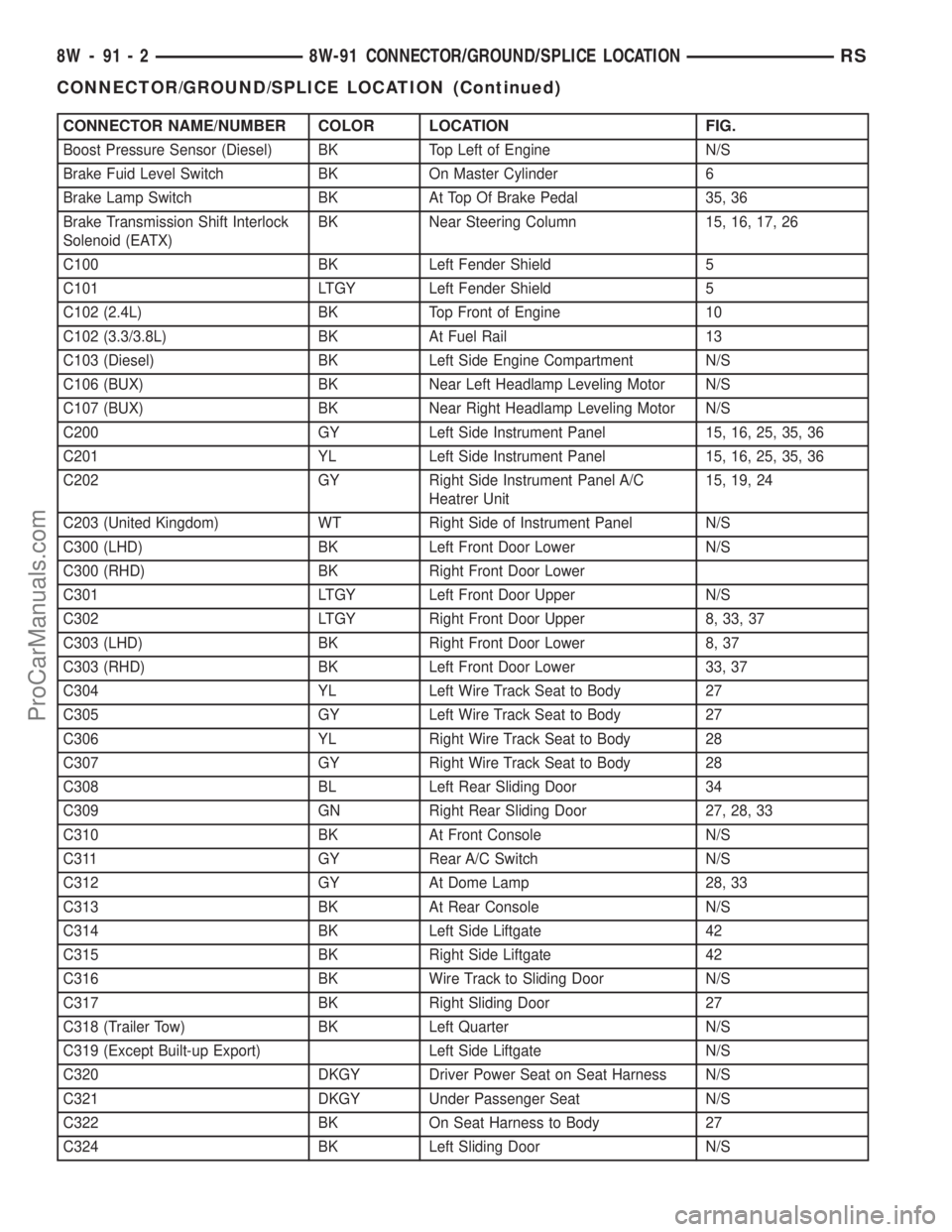
CONNECTOR NAME/NUMBER COLOR LOCATION FIG.
Boost Pressure Sensor (Diesel) BK Top Left of Engine N/S
Brake Fuid Level Switch BK On Master Cylinder 6
Brake Lamp Switch BK At Top Of Brake Pedal 35, 36
Brake Transmission Shift Interlock
Solenoid (EATX)BK Near Steering Column 15, 16, 17, 26
C100 BK Left Fender Shield 5
C101 LTGY Left Fender Shield 5
C102 (2.4L) BK Top Front of Engine 10
C102 (3.3/3.8L) BK At Fuel Rail 13
C103 (Diesel) BK Left Side Engine Compartment N/S
C106 (BUX) BK Near Left Headlamp Leveling Motor N/S
C107 (BUX) BK Near Right Headlamp Leveling Motor N/S
C200 GY Left Side Instrument Panel 15, 16, 25, 35, 36
C201 YL Left Side Instrument Panel 15, 16, 25, 35, 36
C202 GY Right Side Instrument Panel A/C
Heatrer Unit15, 19, 24
C203 (United Kingdom) WT Right Side of Instrument Panel N/S
C300 (LHD) BK Left Front Door Lower N/S
C300 (RHD) BK Right Front Door Lower
C301 LTGY Left Front Door Upper N/S
C302 LTGY Right Front Door Upper 8, 33, 37
C303 (LHD) BK Right Front Door Lower 8, 37
C303 (RHD) BK Left Front Door Lower 33, 37
C304 YL Left Wire Track Seat to Body 27
C305 GY Left Wire Track Seat to Body 27
C306 YL Right Wire Track Seat to Body 28
C307 GY Right Wire Track Seat to Body 28
C308 BL Left Rear Sliding Door 34
C309 GN Right Rear Sliding Door 27, 28, 33
C310 BK At Front Console N/S
C311 GY Rear A/C Switch N/S
C312 GY At Dome Lamp 28, 33
C313 BK At Rear Console N/S
C314 BK Left Side Liftgate 42
C315 BK Right Side Liftgate 42
C316 BK Wire Track to Sliding Door N/S
C317 BK Right Sliding Door 27
C318 (Trailer Tow) BK Left Quarter N/S
C319 (Except Built-up Export) Left Side Liftgate N/S
C320 DKGY Driver Power Seat on Seat Harness N/S
C321 DKGY Under Passenger Seat N/S
C322 BK On Seat Harness to Body 27
C324 BK Left Sliding Door N/S
8W - 91 - 2 8W-91 CONNECTOR/GROUND/SPLICE LOCATIONRS
CONNECTOR/GROUND/SPLICE LOCATION (Continued)
ProCarManuals.com
Page 1153 of 2399
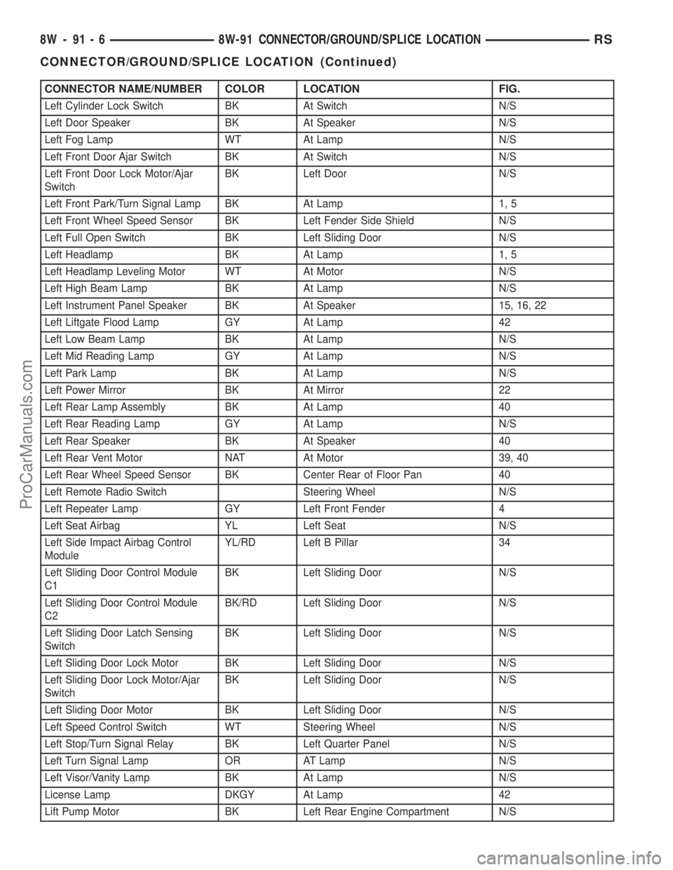
CONNECTOR NAME/NUMBER COLOR LOCATION FIG.
Left Cylinder Lock Switch BK At Switch N/S
Left Door Speaker BK At Speaker N/S
Left Fog Lamp WT At Lamp N/S
Left Front Door Ajar Switch BK At Switch N/S
Left Front Door Lock Motor/Ajar
SwitchBK Left Door N/S
Left Front Park/Turn Signal Lamp BK At Lamp 1, 5
Left Front Wheel Speed Sensor BK Left Fender Side Shield N/S
Left Full Open Switch BK Left Sliding Door N/S
Left Headlamp BK At Lamp 1, 5
Left Headlamp Leveling Motor WT At Motor N/S
Left High Beam Lamp BK At Lamp N/S
Left Instrument Panel Speaker BK At Speaker 15, 16, 22
Left Liftgate Flood Lamp GY At Lamp 42
Left Low Beam Lamp BK At Lamp N/S
Left Mid Reading Lamp GY At Lamp N/S
Left Park Lamp BK At Lamp N/S
Left Power Mirror BK At Mirror 22
Left Rear Lamp Assembly BK At Lamp 40
Left Rear Reading Lamp GY At Lamp N/S
Left Rear Speaker BK At Speaker 40
Left Rear Vent Motor NAT At Motor 39, 40
Left Rear Wheel Speed Sensor BK Center Rear of Floor Pan 40
Left Remote Radio Switch Steering Wheel N/S
Left Repeater Lamp GY Left Front Fender 4
Left Seat Airbag YL Left Seat N/S
Left Side Impact Airbag Control
ModuleYL/RD Left B Pillar 34
Left Sliding Door Control Module
C1BK Left Sliding Door N/S
Left Sliding Door Control Module
C2BK/RD Left Sliding Door N/S
Left Sliding Door Latch Sensing
SwitchBK Left Sliding Door N/S
Left Sliding Door Lock Motor BK Left Sliding Door N/S
Left Sliding Door Lock Motor/Ajar
SwitchBK Left Sliding Door N/S
Left Sliding Door Motor BK Left Sliding Door N/S
Left Speed Control Switch WT Steering Wheel N/S
Left Stop/Turn Signal Relay BK Left Quarter Panel N/S
Left Turn Signal Lamp OR AT Lamp N/S
Left Visor/Vanity Lamp BK At Lamp N/S
License Lamp DKGY At Lamp 42
Lift Pump Motor BK Left Rear Engine Compartment N/S
8W - 91 - 6 8W-91 CONNECTOR/GROUND/SPLICE LOCATIONRS
CONNECTOR/GROUND/SPLICE LOCATION (Continued)
ProCarManuals.com
Page 1154 of 2399
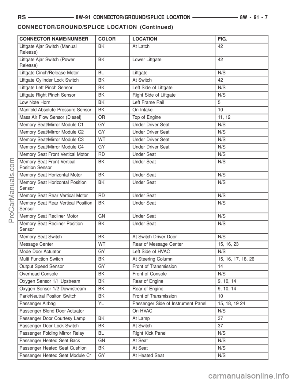
CONNECTOR NAME/NUMBER COLOR LOCATION FIG.
Liftgate Ajar Switch (Manual
Release)BK At Latch 42
Liftgate Ajar Switch (Power
Release)BK Lower Liftgate 42
Liftgate Cinch/Release Motor BL Liftgate N/S
Liftgate Cylinder Lock Switch BK At Switch 42
Liftgate Left Pinch Sensor BK Left Side of Liftgate N/S
Liftgate Right Pinch Sensor BK Right Side of Liftgate N/S
Low Note Horn BK Left Frame Rail 5
Manifold Absolute Pressure Sensor BK On Intake 10
Mass Air Flow Sensor (Diesel) OR Top of Engine 11, 12
Memory Seat/Mirror Module C1 GY Under Driver Seat N/S
Memory Seat/Mirror Module C2 GY Under Driver Seat N/S
Memory Seat/Mirror Module C3 WT Under Driver Seat N/S
Memory Seat/Mirror Module C4 GY Under Driver Seat N/S
Memory Seat Front Vertical Motor RD Under Seat N/S
Memory Seat Front Vertical
Position SensorBK Under Seat N/S
Memory Seat Horizontal Motor BK Under Seat N/S
Memory Seat Horizontal Position
SensorBK Under Seat N/S
Memory Seat Rear Vertical Motor RD Under Seat N/S
Memory Seat Rear Vertical Position
SensorBK Under Seat N/S
Memory Seat Recliner Motor GN Under Seat N/S
Memory Seat Recliner Position
SensorBK Under Seat N/S
Memory Seat Switch BK At Switch Driver Door N/S
Message Center WT Rear of Message Center 15, 16, 23
Mode Door Actuator GY Left Side of HVAC N/S
Multi Function Switch BK At Steering Column 15, 16, 17, 18, 26
Output Speed Sensor GY Front of Transmission 14
Overhead Console BK Front of Console N/S
Oxygen Sensor 1/1 Upstream BK Rear of Engine 9, 10, 14
Oxygen Sensor 1/2 Downstream BK Rear of Engine 9, 10, 14
Park/Neutral Positon Switch BK Front of Transmission 10
Passenger Airbag YL Passenger Side of Instrument Panel 15, 18, 19 24
Passenger Blend Door Actuator On HVAC N/S
Passenger Door Courtesy Lamp BK At Lamp 37
Passenger Door Lock Switch BK At Switch 37
Passenger Folding Mirror Relay BL Right Kick Panel N/S
Passenger Heated Seat Back GN At Seat N/S
Passenger Heated Seat Cushion BK At Seat N/S
Passenger Heated Seat Module C1 GY At Heated Seat N/S
RS8W-91 CONNECTOR/GROUND/SPLICE LOCATION8W-91-7
CONNECTOR/GROUND/SPLICE LOCATION (Continued)
ProCarManuals.com
Page 1155 of 2399
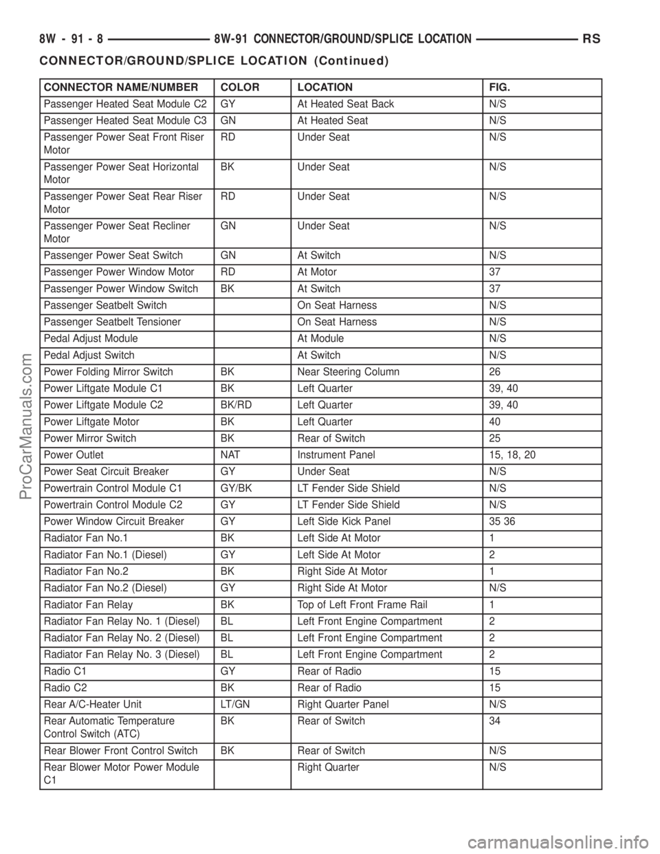
CONNECTOR NAME/NUMBER COLOR LOCATION FIG.
Passenger Heated Seat Module C2 GY At Heated Seat Back N/S
Passenger Heated Seat Module C3 GN At Heated Seat N/S
Passenger Power Seat Front Riser
MotorRD Under Seat N/S
Passenger Power Seat Horizontal
MotorBK Under Seat N/S
Passenger Power Seat Rear Riser
MotorRD Under Seat N/S
Passenger Power Seat Recliner
MotorGN Under Seat N/S
Passenger Power Seat Switch GN At Switch N/S
Passenger Power Window Motor RD At Motor 37
Passenger Power Window Switch BK At Switch 37
Passenger Seatbelt Switch On Seat Harness N/S
Passenger Seatbelt Tensioner On Seat Harness N/S
Pedal Adjust Module At Module N/S
Pedal Adjust Switch At Switch N/S
Power Folding Mirror Switch BK Near Steering Column 26
Power Liftgate Module C1 BK Left Quarter 39, 40
Power Liftgate Module C2 BK/RD Left Quarter 39, 40
Power Liftgate Motor BK Left Quarter 40
Power Mirror Switch BK Rear of Switch 25
Power Outlet NAT Instrument Panel 15, 18, 20
Power Seat Circuit Breaker GY Under Seat N/S
Powertrain Control Module C1 GY/BK LT Fender Side Shield N/S
Powertrain Control Module C2 GY LT Fender Side Shield N/S
Power Window Circuit Breaker GY Left Side Kick Panel 35 36
Radiator Fan No.1 BK Left Side At Motor 1
Radiator Fan No.1 (Diesel) GY Left Side At Motor 2
Radiator Fan No.2 BK Right Side At Motor 1
Radiator Fan No.2 (Diesel) GY Right Side At Motor N/S
Radiator Fan Relay BK Top of Left Front Frame Rail 1
Radiator Fan Relay No. 1 (Diesel) BL Left Front Engine Compartment 2
Radiator Fan Relay No. 2 (Diesel) BL Left Front Engine Compartment 2
Radiator Fan Relay No. 3 (Diesel) BL Left Front Engine Compartment 2
Radio C1 GY Rear of Radio 15
Radio C2 BK Rear of Radio 15
Rear A/C-Heater Unit LT/GN Right Quarter Panel N/S
Rear Automatic Temperature
Control Switch (ATC)BK Rear of Switch 34
Rear Blower Front Control Switch BK Rear of Switch N/S
Rear Blower Motor Power Module
C1Right Quarter N/S
8W - 91 - 8 8W-91 CONNECTOR/GROUND/SPLICE LOCATIONRS
CONNECTOR/GROUND/SPLICE LOCATION (Continued)
ProCarManuals.com
Page 1156 of 2399
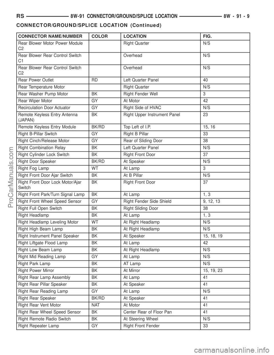
CONNECTOR NAME/NUMBER COLOR LOCATION FIG.
Rear Blower Motor Power Module
C2Right Quarter N/S
Rear Blower Rear Control Switch
C1Overhead N/S
Rear Blower Rear Control Switch
C2Overhead N/S
Rear Power Outlet RD Left Quarter Panel 40
Rear Temperature Motor Right Quarter N/S
Rear Washer Pump Motor BK Right Fender Well 3
Rear Wiper Motor GY At Motor 42
Recirculation Door Actuator GY Right Side of HVAC N/S
Remote Keyless Entry Antenna
(JAPAN)BK Right Upper Instrument Panel 23
Remote Keyless Entry Module BK/RD Top Left of I.P. 15, 16
Right B-Pillar Switch GY Right B Pillar 33
Right Cinch/Release Motor GY Rear of Sliding Door 38
Right Combination Relay BK Left Quarter Panel N/S
Right Cylinder Lock Switch BK Right Front Door 37
Right Door Speaker BK/RD At Speaker N/S
Right Fog Lamp WT At Lamp 3
Right Front Door Ajar Switch BK At B Pillar N/S
Right Front Door Lock Motor/Ajar
SwitchBK Right Front Door 37
Right Front Park/Turn Signal Lamp BK At Lamp 1, 3
Right Front Wheel Speed Sensor GY Right Fender Side Shield 9, 12, 13
Right Full Open Switch BK Right Sliding Door 38
Right Headlamp BK At Lamp 1, 3
Right Headlamp Leveling Motor WT At Right Headlamp N/S
Right High Beam Lamp BK At Right Headlamp N/S
Right Instrument Panel Speaker BK At Speaker 15, 18, 19
Right Liftgate Flood Lamp BK At Lamp 42
Right Low Beam Lamp BK At Right Headlamp N/S
Right Mid Reading Lamp GY At Lamp N/S
Right Park Lamp BK AT Lamp N/S
Right Power Mirror BK At Mirror 15, 19, 23
Right Rear Lamp Assembly BK At Lamp 41
Right Rear Pillar Speaker BK At Speaker 41
Right Rear Reading Lamp GY At Lamp N/S
Right Rear Speaker BK/RD At Speaker 41
Right Rear Vent Motor NAT At Motor 41
Right Rear Wheel Speed Sensor BK Center Rear of Floor Pan 41
Right Remote Radio Switch BK At Steering Wheel N/S
Right Repeater Lamp GY Right Front Fender 33
RS8W-91 CONNECTOR/GROUND/SPLICE LOCATION8W-91-9
CONNECTOR/GROUND/SPLICE LOCATION (Continued)
ProCarManuals.com
Page 1158 of 2399
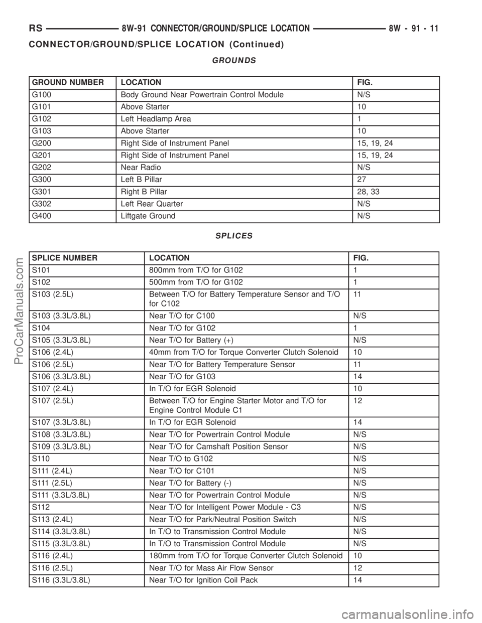
GROUNDS
GROUND NUMBER LOCATION FIG.
G100 Body Ground Near Powertrain Control Module N/S
G101 Above Starter 10
G102 Left Headlamp Area 1
G103 Above Starter 10
G200 Right Side of Instrument Panel 15, 19, 24
G201 Right Side of Instrument Panel 15, 19, 24
G202 Near Radio N/S
G300 Left B Pillar 27
G301 Right B Pillar 28, 33
G302 Left Rear Quarter N/S
G400 Liftgate Ground N/S
SPLICES
SPLICE NUMBER LOCATION FIG.
S101 800mm from T/O for G102 1
S102 500mm from T/O for G102 1
S103 (2.5L) Between T/O for Battery Temperature Sensor and T/O
for C10211
S103 (3.3L/3.8L) Near T/O for C100 N/S
S104 Near T/O for G102 1
S105 (3.3L/3.8L) Near T/O for Battery (+) N/S
S106 (2.4L) 40mm from T/O for Torque Converter Clutch Solenoid 10
S106 (2.5L) Near T/O for Battery Temperature Sensor 11
S106 (3.3L/3.8L) Near T/O for G103 14
S107 (2.4L) In T/O for EGR Solenoid 10
S107 (2.5L) Between T/O for Engine Starter Motor and T/O for
Engine Control Module C112
S107 (3.3L/3.8L) In T/O for EGR Solenoid 14
S108 (3.3L/3.8L) Near T/O for Powertrain Control Module N/S
S109 (3.3L/3.8L) Near T/O for Camshaft Position Sensor N/S
S110 Near T/O to G102 N/S
S111 (2.4L) Near T/O for C101 N/S
S111 (2.5L) Near T/O for Battery (-) N/S
S111 (3.3L/3.8L) Near T/O for Powertrain Control Module N/S
S112 Near T/O for Intelligent Power Module - C3 N/S
S113 (2.4L) Near T/O for Park/Neutral Position Switch N/S
S114 (3.3L/3.8L) In T/O to Transmission Control Module N/S
S115 (3.3L/3.8L) In T/O to Transmission Control Module N/S
S116 (2.4L) 180mm from T/O for Torque Converter Clutch Solenoid 10
S116 (2.5L) Near T/O for Mass Air Flow Sensor 12
S116 (3.3L/3.8L) Near T/O for Ignition Coil Pack 14
RS8W-91 CONNECTOR/GROUND/SPLICE LOCATION8W-91-11
CONNECTOR/GROUND/SPLICE LOCATION (Continued)
ProCarManuals.com
Page 1161 of 2399
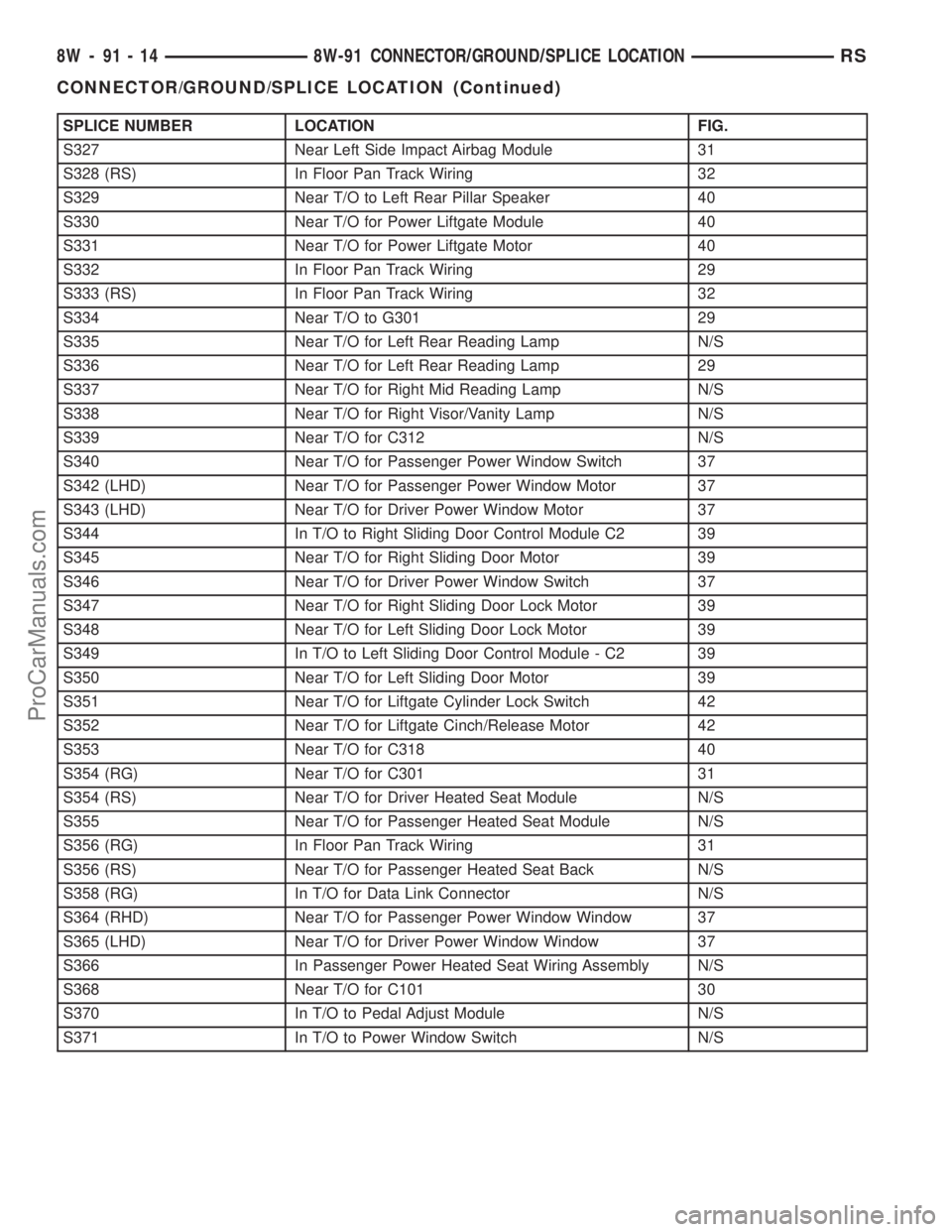
SPLICE NUMBER LOCATION FIG.
S327 Near Left Side Impact Airbag Module 31
S328 (RS) In Floor Pan Track Wiring 32
S329 Near T/O to Left Rear Pillar Speaker 40
S330 Near T/O for Power Liftgate Module 40
S331 Near T/O for Power Liftgate Motor 40
S332 In Floor Pan Track Wiring 29
S333 (RS) In Floor Pan Track Wiring 32
S334 Near T/O to G301 29
S335 Near T/O for Left Rear Reading Lamp N/S
S336 Near T/O for Left Rear Reading Lamp 29
S337 Near T/O for Right Mid Reading Lamp N/S
S338 Near T/O for Right Visor/Vanity Lamp N/S
S339 Near T/O for C312 N/S
S340 Near T/O for Passenger Power Window Switch 37
S342 (LHD) Near T/O for Passenger Power Window Motor 37
S343 (LHD) Near T/O for Driver Power Window Motor 37
S344 In T/O to Right Sliding Door Control Module C2 39
S345 Near T/O for Right Sliding Door Motor 39
S346 Near T/O for Driver Power Window Switch 37
S347 Near T/O for Right Sliding Door Lock Motor 39
S348 Near T/O for Left Sliding Door Lock Motor 39
S349 In T/O to Left Sliding Door Control Module - C2 39
S350 Near T/O for Left Sliding Door Motor 39
S351 Near T/O for Liftgate Cylinder Lock Switch 42
S352 Near T/O for Liftgate Cinch/Release Motor 42
S353 Near T/O for C318 40
S354 (RG) Near T/O for C301 31
S354 (RS) Near T/O for Driver Heated Seat Module N/S
S355 Near T/O for Passenger Heated Seat Module N/S
S356 (RG) In Floor Pan Track Wiring 31
S356 (RS) Near T/O for Passenger Heated Seat Back N/S
S358 (RG) In T/O for Data Link Connector N/S
S364 (RHD) Near T/O for Passenger Power Window Window 37
S365 (LHD) Near T/O for Driver Power Window Window 37
S366 In Passenger Power Heated Seat Wiring Assembly N/S
S368 Near T/O for C101 30
S370 In T/O to Pedal Adjust Module N/S
S371 In T/O to Power Window Switch N/S
8W - 91 - 14 8W-91 CONNECTOR/GROUND/SPLICE LOCATIONRS
CONNECTOR/GROUND/SPLICE LOCATION (Continued)
ProCarManuals.com
Page 1442 of 2399
REAR FASCIA
REMOVAL
(1) Open liftgate.
(2) Remove the two screws attaching the upper
fascia to the fascia support.
(3) Hoist and support vehicle with safety stands.
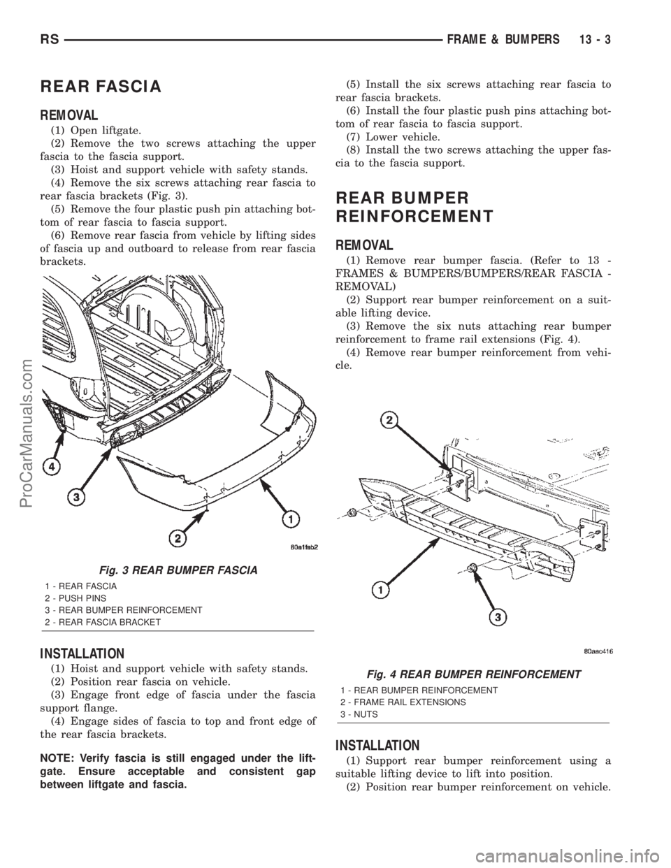
(4) Remove the six screws attaching rear fascia to
rear fascia brackets (Fig. 3).
(5) Remove the four plastic push pin attaching bot-
tom of rear fascia to fascia support.
(6) Remove rear fascia from vehicle by lifting sides
of fascia up and outboard to release from rear fascia
brackets.
INSTALLATION
(1) Hoist and support vehicle with safety stands.
(2) Position rear fascia on vehicle.
(3) Engage front edge of fascia under the fascia
support flange.
(4) Engage sides of fascia to top and front edge of
the rear fascia brackets.
NOTE: Verify fascia is still engaged under the lift-
gate. Ensure acceptable and consistent gap
between liftgate and fascia.(5) Install the six screws attaching rear fascia to
rear fascia brackets.
(6) Install the four plastic push pins attaching bot-
tom of rear fascia to fascia support.
(7) Lower vehicle.
(8) Install the two screws attaching the upper fas-
cia to the fascia support.
REAR BUMPER
REINFORCEMENT
REMOVAL
(1) Remove rear bumper fascia. (Refer to 13 -
FRAMES & BUMPERS/BUMPERS/REAR FASCIA -
REMOVAL)
(2) Support rear bumper reinforcement on a suit-
able lifting device.
(3) Remove the six nuts attaching rear bumper
reinforcement to frame rail extensions (Fig. 4).
(4) Remove rear bumper reinforcement from vehi-
cle.
INSTALLATION
(1) Support rear bumper reinforcement using a
suitable lifting device to lift into position.
(2) Position rear bumper reinforcement on vehicle.
Fig. 3 REAR BUMPER FASCIA
1 - REAR FASCIA
2 - PUSH PINS
3 - REAR BUMPER REINFORCEMENT
2 - REAR FASCIA BRACKET
Fig. 4 REAR BUMPER REINFORCEMENT
1 - REAR BUMPER REINFORCEMENT
2 - FRAME RAIL EXTENSIONS
3 - NUTS
RSFRAME & BUMPERS13-3
ProCarManuals.com