2002 CHRYSLER TOWN AND COUNTRY driver seat adjustment
[x] Cancel search: driver seat adjustmentPage 145 of 2399
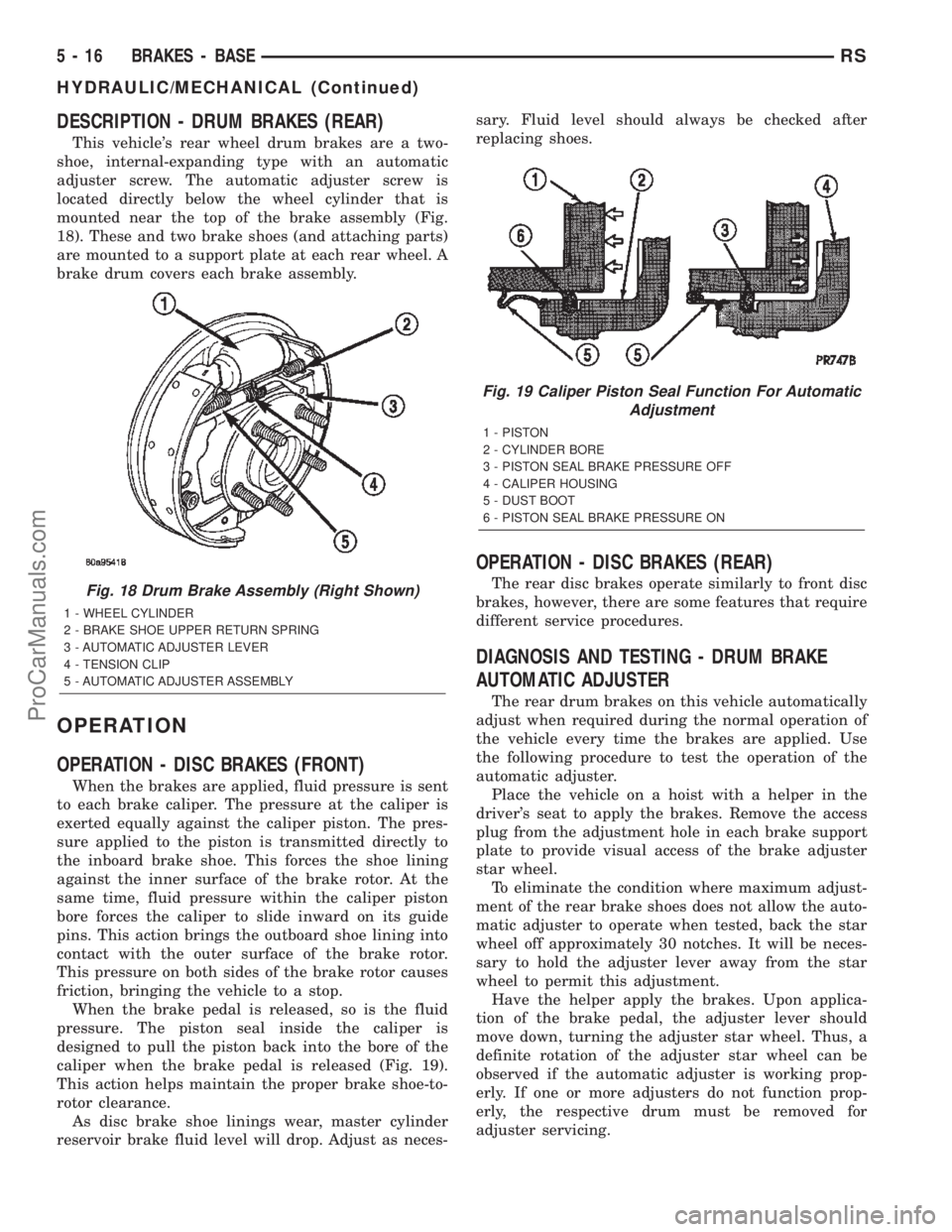
DESCRIPTION - DRUM BRAKES (REAR)
This vehicle's rear wheel drum brakes are a two-
shoe, internal-expanding type with an automatic
adjuster screw. The automatic adjuster screw is
located directly below the wheel cylinder that is
mounted near the top of the brake assembly (Fig.
18). These and two brake shoes (and attaching parts)
are mounted to a support plate at each rear wheel. A
brake drum covers each brake assembly.
OPERATION
OPERATION - DISC BRAKES (FRONT)
When the brakes are applied, fluid pressure is sent
to each brake caliper. The pressure at the caliper is
exerted equally against the caliper piston. The pres-
sure applied to the piston is transmitted directly to
the inboard brake shoe. This forces the shoe lining
against the inner surface of the brake rotor. At the
same time, fluid pressure within the caliper piston
bore forces the caliper to slide inward on its guide
pins. This action brings the outboard shoe lining into
contact with the outer surface of the brake rotor.
This pressure on both sides of the brake rotor causes
friction, bringing the vehicle to a stop.
When the brake pedal is released, so is the fluid
pressure. The piston seal inside the caliper is
designed to pull the piston back into the bore of the
caliper when the brake pedal is released (Fig. 19).
This action helps maintain the proper brake shoe-to-
rotor clearance.
As disc brake shoe linings wear, master cylinder
reservoir brake fluid level will drop. Adjust as neces-sary. Fluid level should always be checked after
replacing shoes.
OPERATION - DISC BRAKES (REAR)
The rear disc brakes operate similarly to front disc
brakes, however, there are some features that require
different service procedures.
DIAGNOSIS AND TESTING - DRUM BRAKE
AUTOMATIC ADJUSTER
The rear drum brakes on this vehicle automatically
adjust when required during the normal operation of
the vehicle every time the brakes are applied. Use
the following procedure to test the operation of the
automatic adjuster.
Place the vehicle on a hoist with a helper in the
driver's seat to apply the brakes. Remove the access
plug from the adjustment hole in each brake support
plate to provide visual access of the brake adjuster
star wheel.
To eliminate the condition where maximum adjust-
ment of the rear brake shoes does not allow the auto-
matic adjuster to operate when tested, back the star
wheel off approximately 30 notches. It will be neces-
sary to hold the adjuster lever away from the star
wheel to permit this adjustment.
Have the helper apply the brakes. Upon applica-
tion of the brake pedal, the adjuster lever should
move down, turning the adjuster star wheel. Thus, a
definite rotation of the adjuster star wheel can be
observed if the automatic adjuster is working prop-
erly. If one or more adjusters do not function prop-
erly, the respective drum must be removed for
adjuster servicing.
Fig. 18 Drum Brake Assembly (Right Shown)
1 - WHEEL CYLINDER
2 - BRAKE SHOE UPPER RETURN SPRING
3 - AUTOMATIC ADJUSTER LEVER
4 - TENSION CLIP
5 - AUTOMATIC ADJUSTER ASSEMBLY
Fig. 19 Caliper Piston Seal Function For Automatic
Adjustment
1 - PISTON
2 - CYLINDER BORE
3 - PISTON SEAL BRAKE PRESSURE OFF
4 - CALIPER HOUSING
5 - DUST BOOT
6 - PISTON SEAL BRAKE PRESSURE ON
5 - 16 BRAKES - BASERS
HYDRAULIC/MECHANICAL (Continued)
ProCarManuals.com
Page 171 of 2399

(5) Install wiring harness connector to brake fluid
level switch mounted in brake fluid reservoir (Fig.
57).
(6) Install battery, clamp and nut.
(7) Install battery shield.
(8) Connect positive battery terminal.
(9) Connect negative battery terminal.
(10) Fill master cylinder with clean, fresh Mopart
Brake Fluid or equivalent.
(11) Road test vehicle to ensure proper operation of
brakes.
INSTALLATION - RHD
CAUTION: Different types of master cylinders are
used on this vehicle depending on brake options. If
a new master cylinder is being installed, be sure it
is the correct master cylinder for the type of brake
system the vehicle is equipped with.
CAUTION: When replacing the master cylinder on a
vehicle, a NEW vacuum seal MUST be installed on
the master cylinder.
(1) Install a NEW vacuum seal on master cylinder
making sure seal fits squarely in groove of master
cylinder casting.
(2) Position master cylinder on studs of power
brake booster, aligning booster push rod with master
cylinder piston.
(3) Install the two master cylinder mounting nuts
(Fig. 59). Tighten both mounting nuts to a torque of
25 N´m (225 in. lbs.).
CAUTION: When tightening the primary and sec-
ondary brake tube nuts at master cylinder, be sure
brake tubes do not contact any other components
within the vehicle and that there is slack in the flex-
ible sections of the tubes. This is required due to
the movement between the ABS ICU and the master
cylinder while the vehicle is in motion.
(4) Connect primary and secondary brake tubes to
master cylinder primary and secondary ports (Fig.
59). Brake tubes must be held securely when tight-
ened to control orientation of flex section. Tighten
tube nuts to a torque of 17 N´m (145 in. lbs.).
(5) Install wiring harness connector to brake fluid
level switch mounted in brake fluid reservoir (Fig.
55).
(6) Install battery, clamp and nut.
(7) Install battery shield.
(8) Connect positive battery terminal.
(9) Connect negative battery terminal.
(10) Fill master cylinder with clean, fresh Mopart
Brake Fluid or equivalent.(11) Road test vehicle to ensure proper operation of
brakes.
PEDAL - ADJUSTABLE
DESCRIPTION
The Adjustable Pedals System (APS) is designed to
enable the fore and aft repositioning of the brake and
accelerator pedals. This results in improved ergonom-
ics in relation to the steering wheel for taller and
shorter drivers. Being able to adjust the pedal posi-
tions also allows the driver to set steering wheel tilt
and seat position to the most comfortable position.
The effort required for pedal application will not
change regardless of pedal position.
The adjustable pedal system allows the pedals to
adjust up to 3 inches (75 mm) at a rate of approxi-
mately 0.4 in./sec. (9 mm/sec.). An adjustment switch
is located on the left side of the steering column
lower shroud.
If the vehicle is equipped with Remote Keyless
Entry (RKE), an optional memory feature is avail-
able.
The serviceable components of the APS are:
²Adjustable pedal assembly (includes motor,
cables, pedals, gear box, sensor and module)
²Adjustable pedal module (Refer to 8 - ELECTRI-
CAL/ELECTRONIC CONTROL MODULES/
ADJUSTABLE PEDAL MODULE)
²Adjustable pedal switch
²Pedal position sensor
OPERATION
Change of pedal position is accomplished by means
of a motor driven screw. Operating the adjustable
pedal switch activates the pedal drive motor. The
pedal drive motor turns a screw that changes the
position of the accelerator pedal. The motor also
drives a cable connected to a gear box that changes
the brake pedal position the same distance as the
accelerator pedal. The pedals can be moved rearward
(closer to the driver) or forward (away from driver).
Each pedal is moved on its activating lever to a posi-
tion where the driver feels most comfortable. The
position and operation of the activating levers are not
changed.
Pedal adjustment is inhibited when the vehicle is
in reverse or when cruise control is engaged. The
Electronic Vehicle Information Center (EVIC) will
display a message when the Adjustable Pedal Module
(APM) is disabled. i.e.:9Adjustable Pedal Disabled -
Cruise Control Engaged9or9Adjustable Pedal Dis-
abled - Vehicle in Reverse9.
Foot pressure or debris can stall pedal adjustment.
In order to avoid damage to system components dur-
5 - 42 BRAKES - BASERS
MASTER CYLINDER (Continued)
ProCarManuals.com
Page 601 of 2399

DRIVER POWER SEAT TRACK
DESCRIPTION
The eight-way power seat option includes a electri-
cally operated power seat track located under each
front seat. The left side power seat track also pro-
vides the mounting location for the body control mod-
ule on this vehicle. The power seat circuit breakers
are mounted on the rear of each power seat track,
just behind the seat rear trim panel. The lower half
of the power seat track is secured to the floor panel
via four studs and nuts that must be accessed from
the underside of the vehicle. Four bolts secure the
bottom of the seat cushion pan to the upper half of
the power seat track unit. Four additional bolts
secure the seat back frame to the power seat track
unit.
The power seat track unit includes four reversible
electric motors that are secured to the upper half of
the track unit. Each motor moves the seat adjuster
through a combination of worm-drive gearboxes and
screw-type drive units. Each of the four power seat
track motors used on models equipped with the
optional memory system incorporates a position
potentiometer integral to the motor assembly, which
electronically monitors the motor position. This
enables the memory system to function by referenc-
ing the motor positions programmed into the memory
seat/mirror module.
The front and rear of the seat are operated by two
separate vertical adjustment motors. These motors
can be operated independently of each other, tilting
the entire seat assembly forward or rearward; or,
they can be operated in unison by selecting the
proper power seat switch functions, which will raise
or lower the entire seat assembly. A third motor is
the horizontal adjustment motor, which moves the
seat track in the forward and rearward directions.
The forth motor is the recliner adjustment motor,
which moves the seat back in the forward and rear-
ward directions.
The power seat track unit cannot be repaired, and
is serviced only as a complete unit. If any component
in this unit is faulty or damaged, the entire power
seat track unit must be replaced.
OPERATION
When a power seat switch control knob or knobs
are actuated, a battery feed and a ground path are
applied through the switch contacts to the power seat
track or recliner adjuster motor. The selected
adjuster motor operates to move the seat track or
recliner through its drive unit in the selected direc-
tion until the switch is released, or until the travel
limit of the adjuster is reached. When the switch is
moved in the opposite direction, the battery feed andground path to the motor are reversed through the
switch contacts. This causes the adjuster motor to
run in the opposite direction.
No power seat switch should be held applied in any
direction after the adjuster has reached its travel
limit. The power seat adjuster motors each contain a
self-resetting circuit breaker to protect them from
overload. However, consecutive or frequent resetting
of the circuit breaker must not be allowed to con-
tinue, or the motor may be damaged.
See the owner's manual in the vehicle glove box for
more information on the power seat switch functions
and the seat adjusting procedures.
DIAGNOSIS AND TESTING - DRIVER POWER
SEAT TRACK
WARNING: SOME VEHICLES ARE EQUIPPED WITH
SEATBACK MOUNTED AIRBAGS. BEFORE
ATTEMPTING TO DIAGNOSE OR SERVICE ANY
SEAT OR POWER SEAT SYSTEM COMPONENT
YOU MUST FIRST DISCONNECT AND ISOLATE THE
BATTERY NEGATIVE CABLE. THEN WAIT TWO MIN-
UTES FOR THE SYSTEM CAPACITOR TO DIS-
CHARGE BEFORE FURTHER SYSTEM SERVICE.
THIS IS THE ONLY SURE WAY TO DISABLE THE
AIRBAG SYSTEM. FAILURE TO DO SO COULD
RESULT IN ACCIDENTAL AIRBAG DEPLOYMENT
AND POSSIBLE PERSONAL INJURY.
Actuate the power seat switch to move all three
power seat track adjusters in each direction. The
power seat track adjusters should move in each of
the selected directions. If a power seat track adjuster
fails to operate in only one direction, move the
adjuster a short distance in the opposite direction
and test again to be certain that the adjuster is not
at its travel limit. If the power seat track adjuster
still fails to operate in only one direction, refer to
Diagnosis and Testing Power Seat Switchin this
section. If the power seat track adjuster fails to oper-
ate in more than one direction, perform the following
tests. For complete circuit diagrams, refer toWiring
Diagrams.
TESTING POWER SEAT TRACK MOTORS
(1) Check the power seat circuit breaker under the
seat. If OK, go to Step 2. If not OK, replace the
faulty power seat circuit breaker.
(2) Check for battery voltage at the power seat cir-
cuit breaker under the seat. If OK, go to Step 3. If
not OK, repair the open fused B(+) circuit to the fuse
in the Intelligent Power Module as required.
(3) Remove the outboard seat cushion side shield
from the seat. Disconnect the seat wire harness con-
nector from the power seat switch connector recepta-
8N - 60 POWER SEAT SYSTEMRS
ProCarManuals.com
Page 602 of 2399

cle. Check for battery voltage at the fused B(+)
circuit cavity of the power seat wire harness connec-
tor for the power seat switch. If OK, go to Step 4. If
not OK, repair the open fused B(+) circuit to the
power seat circuit breaker under the seat as
required.
(4) Check for continuity between the ground cir-
cuit cavity of the power seat wire harness connector
for the power seat switch and a good ground. There
should be continuity. If OK, go to Step 5. If not OK,
repair the open ground circuit to ground as required.
(5) Test the power seat switch. Refer toDiagnosis
and Testing Power Seat Switchin this section. If
the switch tests OK, test the circuits of the power
seat wire harness between the inoperative power seat
track adjuster motor and the power seat switch for
shorts or opens. If the circuits check OK, replace the
faulty power seat track unit. If the circuits are not
OK, repair the power seat wire harness as required.
REMOVAL
WARNING: SOME VEHICLES ARE EQUIPPED WITH
SEATBACK MOUNTED AIRBAGS. BEFORE
ATTEMPTING TO DIAGNOSE OR SERVICE ANY
SEAT OR POWER SEAT SYSTEM COMPONENT
YOU MUST FIRST DISCONNECT AND ISOLATE THE
BATTERY NEGATIVE CABLE. THEN WAIT TWO MIN-
UTES FOR THE SYSTEM CAPACITOR TO DIS-
CHARGE BEFORE FURTHER SYSTEM SERVICE.
THIS IS THE ONLY SURE WAY TO DISABLE THE
AIRBAG SYSTEM. FAILURE TO DO SO COULD
RESULT IN ACCIDENTAL AIRBAG DEPLOYMENT
AND POSSIBLE PERSONAL INJURY.
(1) Remove the appropriate seat from the vehicle
and place it on a clean work surface(Refer to 23 -
BODY/SEATS/SEAT - REMOVAL).
(2) Remove the Body Control Module retaining
screws.
(3) Disconnect the body control module electrical
connectors and remove the body control module from
the power seat track.
(4) Remove the rear fabric blocker trim panel from
the rear of the front seat.
(5) Remove the seat side cover and power seat
switch as an assembly (Refer to 23 - BODY/SEATS/
SEAT CUSHION SIDE COVERS - REMOVAL).
(6) Disconnect all electrical connectors connecting
the power seat track to the seat assembly.
(7) Pull the seat back trim cover up slightly to
access and remove the two seat back frame mounting
bolts and also remove two seat back recliner bolts.
(8) Remove four seat track mounting bolts from
the seat cushion pan.
(9) Remove the power seat track from the seat.
INSTALLATION
(1) Position the seat cushion on the seat track.
(2) Install the four seat track retaining bolts in the
seat cushion pan. Torque the bolts to 28.5 N´m.
(3) Position the seat back and install the two seat
back frame mounting bolts and the two seat back
recliner bolts. Torque the bolts to 55 N´m.
(4) Route and connect the electrical connectors
between the power seat track and the seat assembly.
(5) Install the seat side cover and power seat
switch as an assembly (Refer to 23 - BODY/SEATS/
SEAT CUSHION SIDE COVERS - INSTALLATION).
(6) Install the rear fabric blocker trim panel on the
rear of the front seat.
(7) Position the body control module and connect
the body control module electrical connectors.
(8) Install the Body Control Module retaining
screws.
(9) Install the seat assembly in the vehicle (Refer
to 23 - BODY/SEATS/SEAT - INSTALLATION).
PASSENGER POWER SEAT
TRACK
DESCRIPTION
The eight-way power seat option includes a electri-
cally operated power seat track unit located under
each front seat. The power seat circuit breaker is
mounted on the rear of the power seat track, just
behind the seat rear trim panel. The lower half of the
power seat track is secured to the floor panel via four
studs and nuts that must be accessed from the
underside of the vehicle. Four bolts secure the bot-
tom of the seat cushion frame to the upper half of the
power seat track unit. Four additional bolts secure
the seat back frame to the power seat track unit.
The power seat track unit includes four reversible
electric motors that are secured to the upper half of
the track unit. Each motor moves the seat adjuster
through a combination of worm-drive gearboxes and
screw-type drive units.
The front and rear of the seat are operated by two
separate vertical adjustment motors. These motors
can be operated independently of each other, tilting
the entire seat assembly forward or rearward; or,
they can be operated in unison by selecting the
proper power seat switch functions, which will raise
or lower the entire seat assembly. A third motor is
the horizontal adjustment motor, which moves the
seat track in the forward and rearward directions.
The forth motor is the recliner adjustment motor,
which moves the seat back in the forward and rear-
ward directions.
RSPOWER SEAT SYSTEM8N-61
DRIVER POWER SEAT TRACK (Continued)
ProCarManuals.com
Page 1654 of 2399
(11) Install adapter plate axle seal using Tool
L-4520 (inverted), and driver handle C-4171.
(12) Check differential turning torque. (Refer to 21
- TRANSMISSION/TRANSAXLE/AUTOMATIC -
31TH/BEARINGS - ADJUSTMENTS)
(13) Apply an 1/8º bead of MopartSilicone Rubber
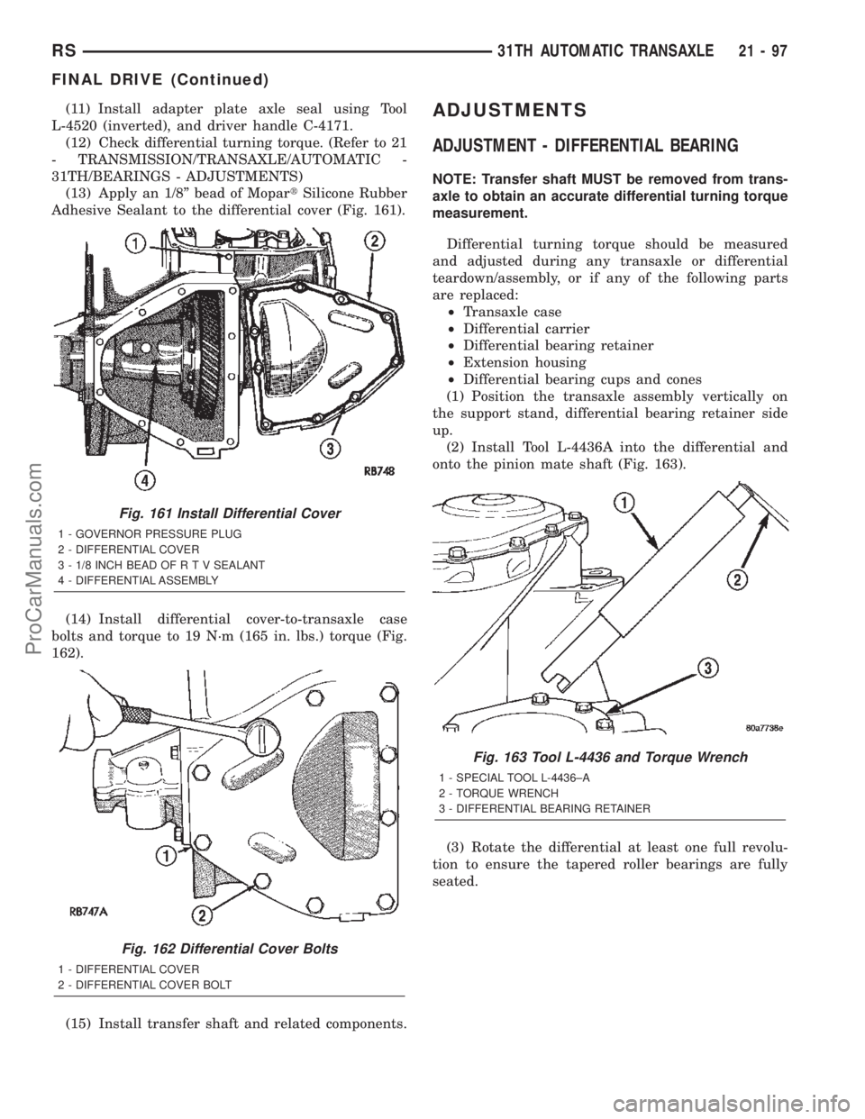
Adhesive Sealant to the differential cover (Fig. 161).
(14) Install differential cover-to-transaxle case
bolts and torque to 19 N´m (165 in. lbs.) torque (Fig.
162).
(15) Install transfer shaft and related components.ADJUSTMENTS
ADJUSTMENT - DIFFERENTIAL BEARING
NOTE: Transfer shaft MUST be removed from trans-
axle to obtain an accurate differential turning torque
measurement.
Differential turning torque should be measured
and adjusted during any transaxle or differential
teardown/assembly, or if any of the following parts
are replaced:
²Transaxle case
²Differential carrier
²Differential bearing retainer
²Extension housing
²Differential bearing cups and cones
(1) Position the transaxle assembly vertically on
the support stand, differential bearing retainer side
up.
(2) Install Tool L-4436A into the differential and
onto the pinion mate shaft (Fig. 163).
(3) Rotate the differential at least one full revolu-
tion to ensure the tapered roller bearings are fully
seated.
Fig. 161 Install Differential Cover
1 - GOVERNOR PRESSURE PLUG
2 - DIFFERENTIAL COVER
3 - 1/8 INCH BEAD OF R T V SEALANT
4 - DIFFERENTIAL ASSEMBLY
Fig. 162 Differential Cover Bolts
1 - DIFFERENTIAL COVER
2 - DIFFERENTIAL COVER BOLT
Fig. 163 Tool L-4436 and Torque Wrench
1 - SPECIAL TOOL L-4436±A
2 - TORQUE WRENCH
3 - DIFFERENTIAL BEARING RETAINER
RS31TH AUTOMATIC TRANSAXLE21-97
FINAL DRIVE (Continued)
ProCarManuals.com
Page 1805 of 2399
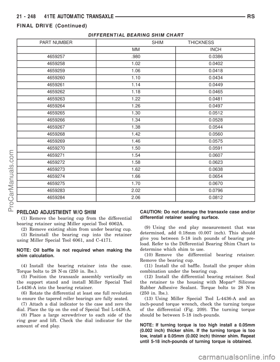
DIFFERENTIAL BEARING SHIM CHART
PART NUMBER SHIM THICKNESS
MM INCH
4659257 .980 0.0386
4659258 1.02 0.0402
4659259 1.06 0.0418
4659260 1.10 0.0434
4659261 1.14 0.0449
4659262 1.18 0.0465
4659263 1.22 0.0481
4659264 1.26 0.0497
4659265 1.30 0.0512
4659266 1.34 0.0528
4659267 1.38 0.0544
4659268 1.42 0.0560
4659269 1.46 0.0575
4659270 1.50 0.0591
4659271 1.54 0.0607
4659272 1.58 0.0623
4659273 1.62 0.0638
4659274 1.66 0.0654
4659275 1.70 0.0670
4659283 2.02 0.0796
4659284 2.06 0.0812
PRELOAD ADJUSTMENT W/O SHIM
(1) Remove the bearing cup from the differential
bearing retainer using Miller special Tool 6062A.
(2) Remove existing shim from under bearing cup.
(3) Reinstall the bearing cup into the retainer
using Miller Special Tool 6061, and C-4171.
NOTE: Oil baffle is not required when making the
shim calculation.
(4) Install the bearing retainer into the case.
Torque bolts to 28 N´m (250 in. lbs.).
(5) Position the transaxle assembly vertically on
the support stand and install Miller Special Tool
L-4436-A into the bearing retainer.
(6)
Rotate the differential at least one full revolution
to ensure the tapered roller bearings are fully seated.
(7)Attach a dial indicator to the case and zero the
dial. Place the tip on the end of Special Tool L-4436-A.
(8) Place a large screwdriver to each side of the
ring gear and lift. Check the dial indicator for the
amount of end play.CAUTION: Do not damage the transaxle case and/or
differential retainer sealing surface.
(9) Using the end play measurement that was
determined, add 0.18mm (0.007 inch). This should
give you between 5-18 inch pounds of bearing pre-
load. Refer to the Differential Bearing Shim Chart to
determine which shim to use.
(10) Remove the differential bearing retainer.
Remove the bearing cup.
(11) Install the oil baffle. Install the proper shim
combination under the bearing cup.
(12) Install the differential bearing retainer. Seal
the retainer to the housing with MopartSilicone
Rubber Adhesive Sealant. Torque bolts to 28 N´m
(250 in. lbs.).
(13) Using Miller Special Tool L-4436-A and an
inch-pound torque wrench, check the turning torque
of the differential (Fig. 209). The turning torque
should be between 5-18 inch-pounds.
NOTE: If turning torque is too high install a 0.05mm
(0.002 inch) thicker shim. If the turning torque is too
low, install a 0.05mm (0.002 inch) thinner shim. Repeat
until 5-18 inch-pounds of turning torque is obtained.
21 - 248 41TE AUTOMATIC TRANSAXLERS
FINAL DRIVE (Continued)
ProCarManuals.com
Page 2074 of 2399
(1) Remove head rest sleeves. (Refer to 23 - BODY/
SEATS/HEADREST SLEEVE - REMOVAL)
(2) Remove the armrest. (Refer to 23 - BODY/
SEATS/ARMREST - REMOVAL)
(3) Remove the seatback recliner lever.
(4) Remove the lumbar adjustment lever.
(5) Remove both seat cushion side covers. (Refer to
23 - BODY/SEATS/FRONT SEAT CUSHION SIDE
COVER - REMOVAL)
(6) Remove nut attaching the recliner to the seat-
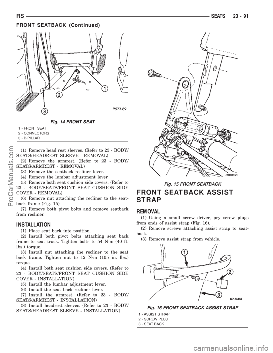
back frame (Fig. 15).
(7) Remove both pivot bolts and remove seatback
from recliner.
INSTALLATION
(1) Place seat back into position.
(2) Install both pivot bolts attaching seat back
frame to seat track. Tighten bolts to 54 N´m (40 ft.
lbs.) torque.
(3) Install nut attaching the recliner to the seat
back frame. Tighten nut to 12 N´m (105 in. lbs.)
torque.
(4) Install both seat cushion side covers. (Refer to
23 - BODY/SEATS/FRONT SEAT CUSHION SIDE
COVER - INSTALLATION)
(5) Install the lumbar adjustment lever.
(6) Install the seat back recliner lever.
(7) Install the armrest. (Refer to 23 - BODY/
SEATS/ARMREST - INSTALLATION)
(8) Install headrest sleeves. (Refer to 23 - BODY/
SEATS/HEADREST SLEEVE - INSTALLATION)
FRONT SEATBACK ASSIST
STRAP
REMOVAL
(1) Using a small screw driver, pry screw plugs
from ends of assist strap (Fig. 16).
(2) Remove screws attaching assist strap to seat-
back.
(3) Remove assist strap from vehicle.
Fig. 14 FRONT SEAT
1 - FRONT SEAT
2 - CONNECTORS
3 - B-PILLAR
Fig. 15 FRONT SEATBACK
Fig. 16 FRONT SEATBACK ASSIST STRAP
1 - ASSIST STRAP
2 - SCREW PLUG
3 - SEAT BACK
RSSEATS23-91
FRONT SEATBACK (Continued)
ProCarManuals.com
Page 2245 of 2399
FRONT CONTROL PANEL
The front control panel and integral computer is
mounted in the instrument panel.
The instrument panel mounted control and inte-
gral computer contains:
²a power button which allows the system to be
completely turned off.
²rear window defogger on/off switch.
²slide controls for completely independent side-to-
side temperature control of the discharge air. The full
range of temperature that the system can produce in
any mode is available on either side of the vehicle by
independently positioning the slide controls on the
instrument panel.
²air recirculation button. The Recirculate button
contains an LED that illuminates to show when the
function is in operation.
²an air conditioning button that allows the com-
pressor to be turned on/off. The Snowflake button
contains an LED that illuminates to shown when the
function is in operation.
²rotary knobs for front and rear fan speed selec-
tion.
²a rotary knob for mode control.
REAR CONTROL PANEL
A rear control panel centrally mounted on the
headliner has a rotary adjustment for temperature
and fan speed control of the rear unit by intermedi-
ate seat passengers when the front control rear knob
is set to the rear position.
DESCRIPTION - THREE ZONE AUTOMATIC
TEMPERATURE CONTROL
The Three-Zone Automatic Temperature Control
(ATC) allows occupants to select a comfort tempera-
ture, which is the perceived temperature level not
the actual passenger compartment air temperature.
The Three Zone Automatic Temperature Control
system includes a dust and odor air filter. The filter
element is the same size as the air conditioning evap-
orator to ensure ample capacity. A door at the base of
the heater and air conditioning housing below the
glove box provides easy access to the filter element.
The ATC computer utilizes integrated circuitry and
information carried on the Programmable Communi-
cations Interface (PCI) data bus network to monitor
many sensors and switch inputs throughout the vehi-
cle. In response to those inputs, the internal circuitry
and programming of the ATC computer allow it to
control electronic functions and features of the ATC
system. The inputs to the ATC computer are:
²Vehicle Speed/Engine RPM± The ATC com-
puter monitors engine RPM, vehicle speed and Man-
ifold Absolute Pressure information from the PCM.²Coolant Temperature± ATC computer moni-
tors Coolant temperature received from the PCM and
converts it to degrees Fahrenheit.
²Ambient Temperature± ATC computer moni-
tors Ambient temperature from the Compass Mini
Trip Computer (CMTC) and converts it to degrees
Fahrenheit.
²Engine Miscellaneous Sensor Status±ATC
computer monitors A/C disable information from the
PCM.
²Refrigerant Pressure± ATC computer moni-
tors Barometric Pressure, Intake Air Temperature,
High Side Pressure and Methanol Content as broad-
cast by the PCM.
²Door Ajar Status± The ATC computer moni-
tors Driver Front Door, Passenger Front Door, Left
Rear Door, Right Rear Door and Liftgate ajar infor-
mation, as identified by the Body Control Module
(BCM), to determine if all in-car temperatures should
be maintained.
²Dimming± The ATC computer monitors dim-
ming status from the BCM to determine the required
level of brightness and will dim accordingly.
²Vehicle Odometer± The ATC computer moni-
tors the vehicle odometer information from the BCM
to prevent flashing the VF tube icons if the manual
motor calibration or manual cool down tests have
failed. Flashing of the display icons will cease when
the vehicle odometer is greater than 3 miles.
²English Metric± The ATC computer monitors
the English/Metric information broadcast by the
CMTC. The set temp displays for both the front and
rear control heads will be set accordingly.
²Vehicle Identification Number± The ATC
computer monitors the last eight characters of the
VIN broadcast by the PCM and compares it to the
information stored in EEPROM. If it is different, the
new number will be stored over the old one and a
motor calibration shall be initiated.
²A/C System Information± The ATC computer
will send a message for Evaporator Temperature too
Low, Fan Blower Relay status, Evaporator Sensor
Failure, Rear Window Defogger Relay and A/C Select.
FRONT CONTROL PANEL
The front control panel and integral computer is
mounted in the instrument panel.
The instrument panel mounted control and inte-
gral computer contains:
²A power button which allows the system to be
completely turned off. The display is blank when the
system is off.
²Three rocker switches that select comfort tem-
peratures from 15É to 30É C (59É to 85É F), which are
shown in the vacuum-fluorescent digital control dis-
play. If the set temp is 59 and the down button is
24 - 2 HEATING & AIR CONDITIONINGRS
HEATING & AIR CONDITIONING (Continued)
ProCarManuals.com