2002 CHRYSLER TOWN AND COUNTRY rear gate
[x] Cancel search: rear gatePage 1995 of 2399
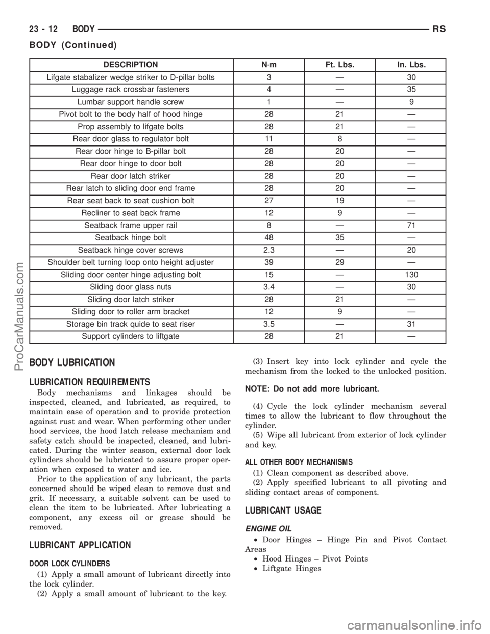
DESCRIPTION N´m Ft. Lbs. In. Lbs.
Lifgate stabalizer wedge striker to D-pillar bolts 3 Ð 30
Luggage rack crossbar fasteners 4 Ð 35
Lumbar support handle screw 1 Ð 9
Pivot bolt to the body half of hood hinge 28 21 Ð
Prop assembly to lifgate bolts 28 21 Ð
Rear door glass to regulator bolt 11 8 Ð
Rear door hinge to B-pillar bolt 28 20 Ð
Rear door hinge to door bolt 28 20 Ð
Rear door latch striker 28 20 Ð
Rear latch to sliding door end frame 28 20 Ð
Rear seat back to seat cushion bolt 27 19 Ð
Recliner to seat back frame 12 9 Ð
Seatback frame upper rail 8 Ð 71
Seatback hinge bolt 48 35 Ð
Seatback hinge cover screws 2.3 Ð 20
Shoulder belt turning loop onto height adjuster 39 29 Ð
Sliding door center hinge adjusting bolt 15 Ð 130
Sliding door glass nuts 3.4 Ð 30
Sliding door latch striker 28 21 Ð
Sliding door to roller arm bracket 12 9 Ð
Storage bin track quide to seat riser 3.5 Ð 31
Support cylinders to liftgate 28 21 Ð
BODY LUBRICATION
LUBRICATION REQUIREMENTS
Body mechanisms and linkages should be
inspected, cleaned, and lubricated, as required, to
maintain ease of operation and to provide protection
against rust and wear. When performing other under
hood services, the hood latch release mechanism and
safety catch should be inspected, cleaned, and lubri-
cated. During the winter season, external door lock
cylinders should be lubricated to assure proper oper-
ation when exposed to water and ice.
Prior to the application of any lubricant, the parts
concerned should be wiped clean to remove dust and
grit. If necessary, a suitable solvent can be used to
clean the item to be lubricated. After lubricating a
component, any excess oil or grease should be
removed.
LUBRICANT APPLICATION
DOOR LOCK CYLINDERS
(1) Apply a small amount of lubricant directly into
the lock cylinder.
(2) Apply a small amount of lubricant to the key.(3) Insert key into lock cylinder and cycle the
mechanism from the locked to the unlocked position.
NOTE: Do not add more lubricant.
(4) Cycle the lock cylinder mechanism several
times to allow the lubricant to flow throughout the
cylinder.
(5) Wipe all lubricant from exterior of lock cylinder
and key.
ALL OTHER BODY MECHANISMS
(1) Clean component as described above.
(2) Apply specified lubricant to all pivoting and
sliding contact areas of component.
LUBRICANT USAGE
ENGINE OIL
²Door Hinges ± Hinge Pin and Pivot Contact
Areas
²Hood Hinges ± Pivot Points
²Liftgate Hinges
23 - 12 BODYRS
BODY (Continued)
ProCarManuals.com
Page 2002 of 2399
(2) Place door latch in position on door end frame.
(3) Install screws attaching door latch to door end
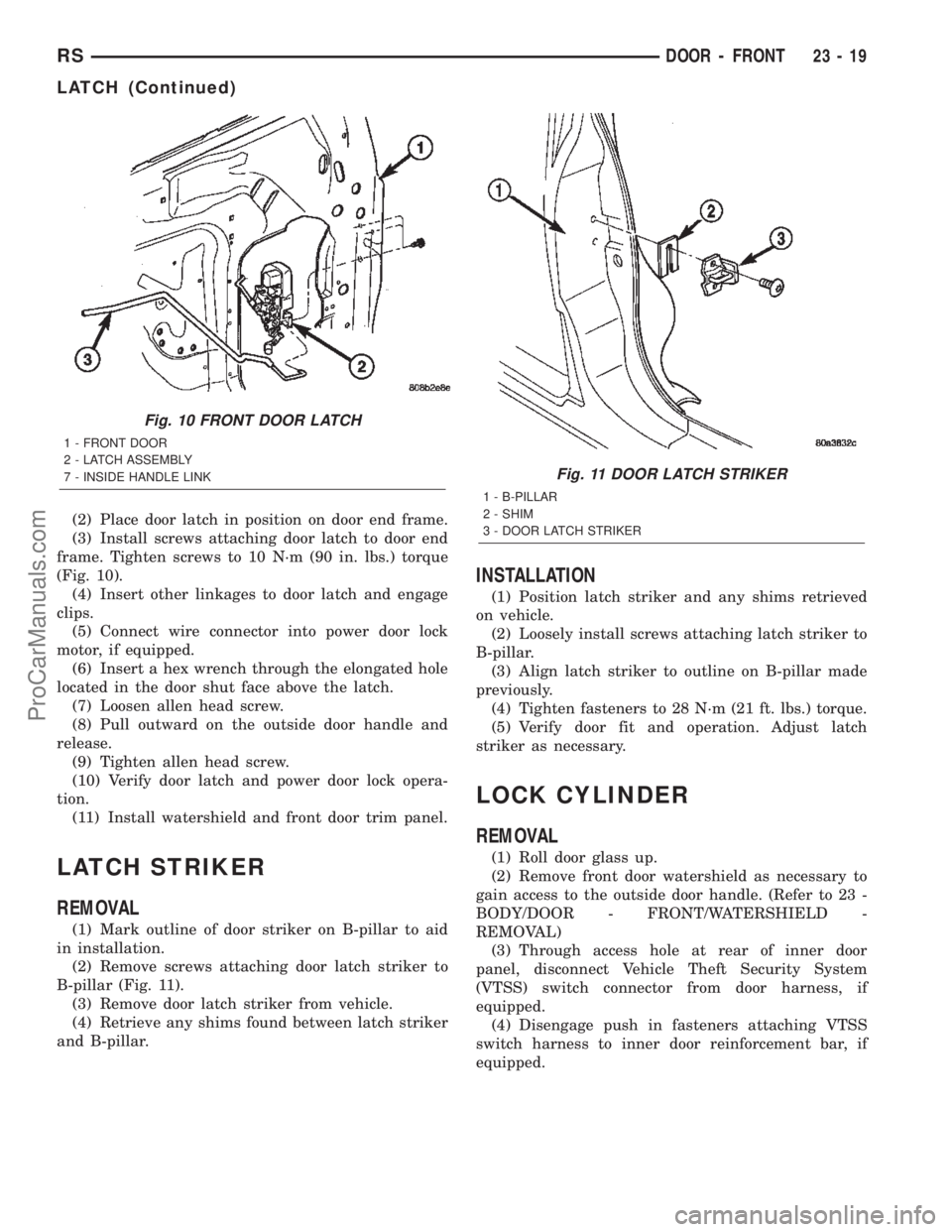
frame. Tighten screws to 10 N´m (90 in. lbs.) torque
(Fig. 10).
(4) Insert other linkages to door latch and engage
clips.
(5) Connect wire connector into power door lock
motor, if equipped.
(6) Insert a hex wrench through the elongated hole
located in the door shut face above the latch.
(7) Loosen allen head screw.
(8) Pull outward on the outside door handle and
release.
(9) Tighten allen head screw.
(10) Verify door latch and power door lock opera-
tion.
(11) Install watershield and front door trim panel.
LATCH STRIKER
REMOVAL
(1) Mark outline of door striker on B-pillar to aid
in installation.
(2) Remove screws attaching door latch striker to
B-pillar (Fig. 11).
(3) Remove door latch striker from vehicle.
(4) Retrieve any shims found between latch striker
and B-pillar.
INSTALLATION
(1) Position latch striker and any shims retrieved
on vehicle.
(2) Loosely install screws attaching latch striker to
B-pillar.
(3) Align latch striker to outline on B-pillar made
previously.
(4) Tighten fasteners to 28 N´m (21 ft. lbs.) torque.
(5) Verify door fit and operation. Adjust latch
striker as necessary.
LOCK CYLINDER
REMOVAL
(1) Roll door glass up.
(2) Remove front door watershield as necessary to
gain access to the outside door handle. (Refer to 23 -
BODY/DOOR - FRONT/WATERSHIELD -
REMOVAL)
(3) Through access hole at rear of inner door
panel, disconnect Vehicle Theft Security System
(VTSS) switch connector from door harness, if
equipped.
(4) Disengage push in fasteners attaching VTSS
switch harness to inner door reinforcement bar, if
equipped.
Fig. 10 FRONT DOOR LATCH
1 - FRONT DOOR
2 - LATCH ASSEMBLY
7 - INSIDE HANDLE LINK
Fig. 11 DOOR LATCH STRIKER
1 - B-PILLAR
2 - SHIM
3 - DOOR LATCH STRIKER
RSDOOR - FRONT23-19
LATCH (Continued)
ProCarManuals.com
Page 2023 of 2399
(5) Align hinge to marks on roof header.
(6) Install bolts attaching liftgate hinge to roof
header. Tighten outer two bolts to 33 N´m (24 ft. lbs.)
torque. The sheet medal screw at center 12 N´m (105
in. lbs.)
(7) Remove duct tape from roof and liftgate.
(8) Verify liftgate alignment. Refer to Liftgate
Remove and Installation for proper gap measure-
ments.
LATCH
REMOVAL
(1) Remove liftgate trim panel.
(2) Disengage outside handle link from clip on
latch.
(3) Disconnect wire connector from liftgate latch
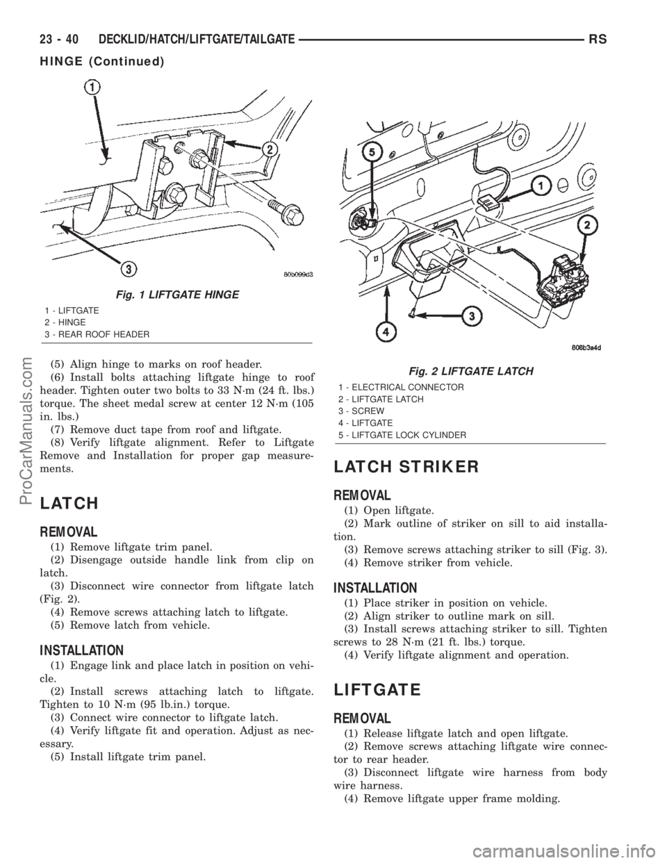
(Fig. 2).
(4) Remove screws attaching latch to liftgate.
(5) Remove latch from vehicle.
INSTALLATION
(1) Engage link and place latch in position on vehi-
cle.
(2) Install screws attaching latch to liftgate.
Tighten to 10 N´m (95 lb.in.) torque.
(3) Connect wire connector to liftgate latch.
(4) Verify liftgate fit and operation. Adjust as nec-
essary.
(5) Install liftgate trim panel.
LATCH STRIKER
REMOVAL
(1) Open liftgate.
(2) Mark outline of striker on sill to aid installa-
tion.
(3) Remove screws attaching striker to sill (Fig. 3).
(4) Remove striker from vehicle.
INSTALLATION
(1) Place striker in position on vehicle.
(2) Align striker to outline mark on sill.
(3) Install screws attaching striker to sill. Tighten
screws to 28 N´m (21 ft. lbs.) torque.
(4) Verify liftgate alignment and operation.
LIFTGATE
REMOVAL
(1) Release liftgate latch and open liftgate.
(2) Remove screws attaching liftgate wire connec-
tor to rear header.
(3) Disconnect liftgate wire harness from body
wire harness.
(4) Remove liftgate upper frame molding.
Fig. 1 LIFTGATE HINGE
1 - LIFTGATE
2 - HINGE
3 - REAR ROOF HEADER
Fig. 2 LIFTGATE LATCH
1 - ELECTRICAL CONNECTOR
2 - LIFTGATE LATCH
3 - SCREW
4 - LIFTGATE
5 - LIFTGATE LOCK CYLINDER
23 - 40 DECKLID/HATCH/LIFTGATE/TAILGATERS
HINGE (Continued)
ProCarManuals.com
Page 2024 of 2399
(5) Disconnect rear window washer hose from
spray nozzle.
(6) Support liftgate on a suitable lifting device.
(7) Remove screws attaching support cylinders to
liftgate.
(8) Remove bolts attaching liftgate hinge to roof
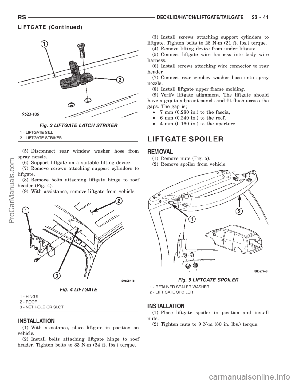
header (Fig. 4).
(9) With assistance, remove liftgate from vehicle.
INSTALLATION
(1) With assistance, place liftgate in position on
vehicle.
(2) Install bolts attaching liftgate hinge to roof
header. Tighten bolts to 33 N´m (24 ft. lbs.) torque.(3) Install screws attaching support cylinders to
liftgate. Tighten bolts to 28 N´m (21 ft. lbs.) torque.
(4) Remove lifting device from under liftgate.
(5) Connect liftgate wire harness into body wire
harness.
(6) Install screws attaching wire connector to rear
header.
(7) Connect rear window washer hose onto spray
nozzle.
(8) Install liftgate upper frame molding.
(9) Verify liftgate alignment. The liftgate should
have a gap to adjacent panels and fit flush across the
gaps. The gap is;
²7 mm (0.280 in.) to the fascia,
²6 mm (0.240 in.) to the roof,
²4 mm (0.160 in.) to the aperture.
LIFTGATE SPOILER
REMOVAL
(1) Remove nuts (Fig. 5).
(2) Remove spoiler from vehicle.
INSTALLATION
(1) Place liftgate spoiler in position and install
nuts.
(2) Tighten nuts to 9 N´m (80 in. lbs.) torque.
Fig. 3 LIFTGATE LATCH STRIKER
1 - LIFTGATE SILL
2 - LIFTGATE STRIKER
Fig. 4 LIFTGATE
1 - HINGE
2 - ROOF
3 - NET HOLE OR SLOT
Fig. 5 LIFTGATE SPOILER
1 - RETAINER SEALER WASHER
2 - LIFT GATE SPOILER
RSDECKLID/HATCH/LIFTGATE/TAILGATE23-41
LIFTGATE (Continued)
ProCarManuals.com
Page 2032 of 2399
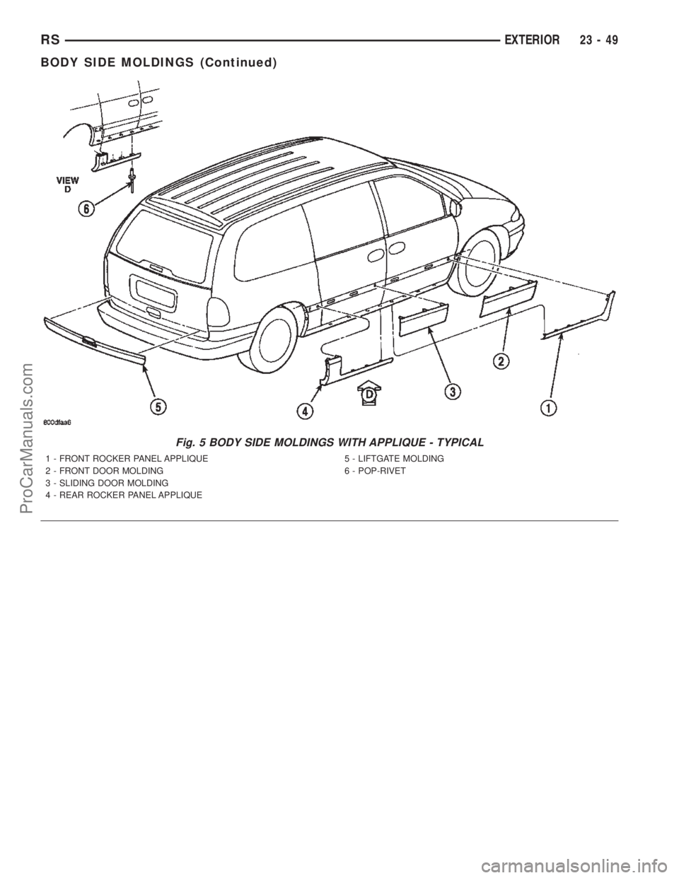
Fig. 5 BODY SIDE MOLDINGS WITH APPLIQUE - TYPICAL
1 - FRONT ROCKER PANEL APPLIQUE
2 - FRONT DOOR MOLDING
3 - SLIDING DOOR MOLDING
4 - REAR ROCKER PANEL APPLIQUE5 - LIFTGATE MOLDING
6 - POP-RIVET
RSEXTERIOR23-49
BODY SIDE MOLDINGS (Continued)
ProCarManuals.com
Page 2055 of 2399
INTERIOR
TABLE OF CONTENTS
page page
A-PILLAR LOWER EXTENSION TRIM
REMOVAL.............................73
INSTALLATION.........................73
A-PILLAR TRIM
REMOVAL.............................73
INSTALLATION.........................73
ASSIST HANDLE
REMOVAL.............................73
INSTALLATION.........................73
B-PILLAR LOWER TRIM
REMOVAL.............................73
INSTALLATION.........................74
B-PILLAR UPPER TRIM
REMOVAL.............................74
INSTALLATION.........................74
CARPETS AND FLOOR MATS
REMOVAL.............................74
INSTALLATION.........................75
COWL TRIM
REMOVAL.............................75
INSTALLATION.........................75
C-PILLAR TRIM
REMOVAL.............................75
INSTALLATION.........................76
DOOR SILL TRIM PLATE
REMOVAL.............................76
INSTALLATION.........................76
HEADLINER
REMOVAL.............................76
INSTALLATION.........................76
LEFT D-PILLAR TRIM PANEL
REMOVAL.............................77
INSTALLATION.........................77
LIFTGATE SILL PLATE
REMOVAL.............................77
INSTALLATION.........................77
QUARTER TRIM BOLSTER
REMOVAL.............................77INSTALLATION.........................77
RIGHT QUARTER TRIM PANEL
REMOVAL.............................78
INSTALLATION.........................78
LEFT QUARTER TRIM PANEL
REMOVAL.............................78
INSTALLATION.........................78
REAR HEADER TRIM
REMOVAL.............................79
INSTALLATION.........................79
REAR HVAC LOUVER
REMOVAL.............................79
INSTALLATION.........................79
REAR VIEW MIRROR
REMOVAL.............................80
INSTALLATION.........................80
RIGHT D-PILLAR TRIM PANEL
REMOVAL.............................80
INSTALLATION.........................80
SLIDING DOOR SILL PLATE
REMOVAL.............................80
INSTALLATION.........................80
SUN VISOR
REMOVAL.............................81
INSTALLATION.........................81
SUN VISOR SUPPORT
REMOVAL.............................81
INSTALLATION.........................81
FLOOR CONSOLE TRAY
REMOVAL.............................82
INSTALLATION.........................82
FLOOR CONSOLE TRAY - BRACKET
ASSEMBLY
REMOVAL.............................82
INSTALLATION.........................82
23 - 72 INTERIORRS
ProCarManuals.com
Page 2057 of 2399
(5) Disengage hidden clips attaching lower trim
cover to B-pillar.
(6) Remove lower B-pillar trim cover from vehicle.
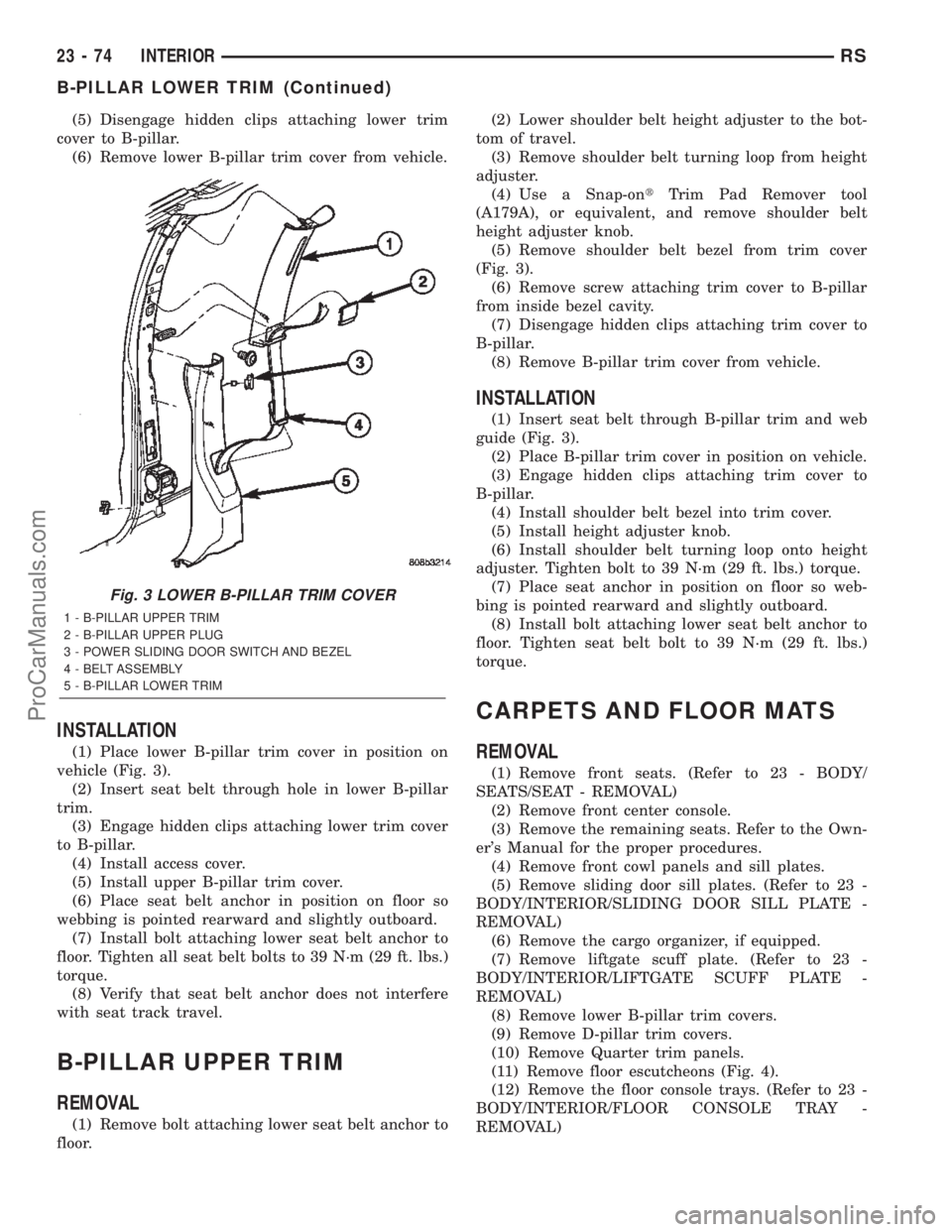
INSTALLATION
(1) Place lower B-pillar trim cover in position on
vehicle (Fig. 3).
(2) Insert seat belt through hole in lower B-pillar
trim.
(3) Engage hidden clips attaching lower trim cover
to B-pillar.
(4) Install access cover.
(5) Install upper B-pillar trim cover.
(6) Place seat belt anchor in position on floor so
webbing is pointed rearward and slightly outboard.
(7) Install bolt attaching lower seat belt anchor to
floor. Tighten all seat belt bolts to 39 N´m (29 ft. lbs.)
torque.
(8) Verify that seat belt anchor does not interfere
with seat track travel.
B-PILLAR UPPER TRIM
REMOVAL
(1) Remove bolt attaching lower seat belt anchor to
floor.(2) Lower shoulder belt height adjuster to the bot-
tom of travel.
(3) Remove shoulder belt turning loop from height
adjuster.
(4) Use a Snap-ontTrim Pad Remover tool
(A179A), or equivalent, and remove shoulder belt
height adjuster knob.
(5) Remove shoulder belt bezel from trim cover
(Fig. 3).
(6) Remove screw attaching trim cover to B-pillar
from inside bezel cavity.
(7) Disengage hidden clips attaching trim cover to
B-pillar.
(8) Remove B-pillar trim cover from vehicle.
INSTALLATION
(1) Insert seat belt through B-pillar trim and web
guide (Fig. 3).
(2) Place B-pillar trim cover in position on vehicle.
(3) Engage hidden clips attaching trim cover to
B-pillar.
(4) Install shoulder belt bezel into trim cover.
(5) Install height adjuster knob.
(6) Install shoulder belt turning loop onto height
adjuster. Tighten bolt to 39 N´m (29 ft. lbs.) torque.
(7) Place seat anchor in position on floor so web-
bing is pointed rearward and slightly outboard.
(8) Install bolt attaching lower seat belt anchor to
floor. Tighten seat belt bolt to 39 N´m (29 ft. lbs.)
torque.
CARPETS AND FLOOR MATS
REMOVAL
(1) Remove front seats. (Refer to 23 - BODY/
SEATS/SEAT - REMOVAL)
(2) Remove front center console.
(3) Remove the remaining seats. Refer to the Own-
er's Manual for the proper procedures.
(4) Remove front cowl panels and sill plates.
(5) Remove sliding door sill plates. (Refer to 23 -
BODY/INTERIOR/SLIDING DOOR SILL PLATE -
REMOVAL)
(6) Remove the cargo organizer, if equipped.
(7) Remove liftgate scuff plate. (Refer to 23 -
BODY/INTERIOR/LIFTGATE SCUFF PLATE -
REMOVAL)
(8) Remove lower B-pillar trim covers.
(9) Remove D-pillar trim covers.
(10) Remove Quarter trim panels.
(11) Remove floor escutcheons (Fig. 4).
(12) Remove the floor console trays. (Refer to 23 -
BODY/INTERIOR/FLOOR CONSOLE TRAY -
REMOVAL)
Fig. 3 LOWER B-PILLAR TRIM COVER
1 - B-PILLAR UPPER TRIM
2 - B-PILLAR UPPER PLUG
3 - POWER SLIDING DOOR SWITCH AND BEZEL
4 - BELT ASSEMBLY
5 - B-PILLAR LOWER TRIM
23 - 74 INTERIORRS
B-PILLAR LOWER TRIM (Continued)
ProCarManuals.com
Page 2059 of 2399
(4) Disengage hidden clips attaching trim to upper
C-pillar.
(5) Remove upper C-pillar trim from vehicle.
INSTALLATION
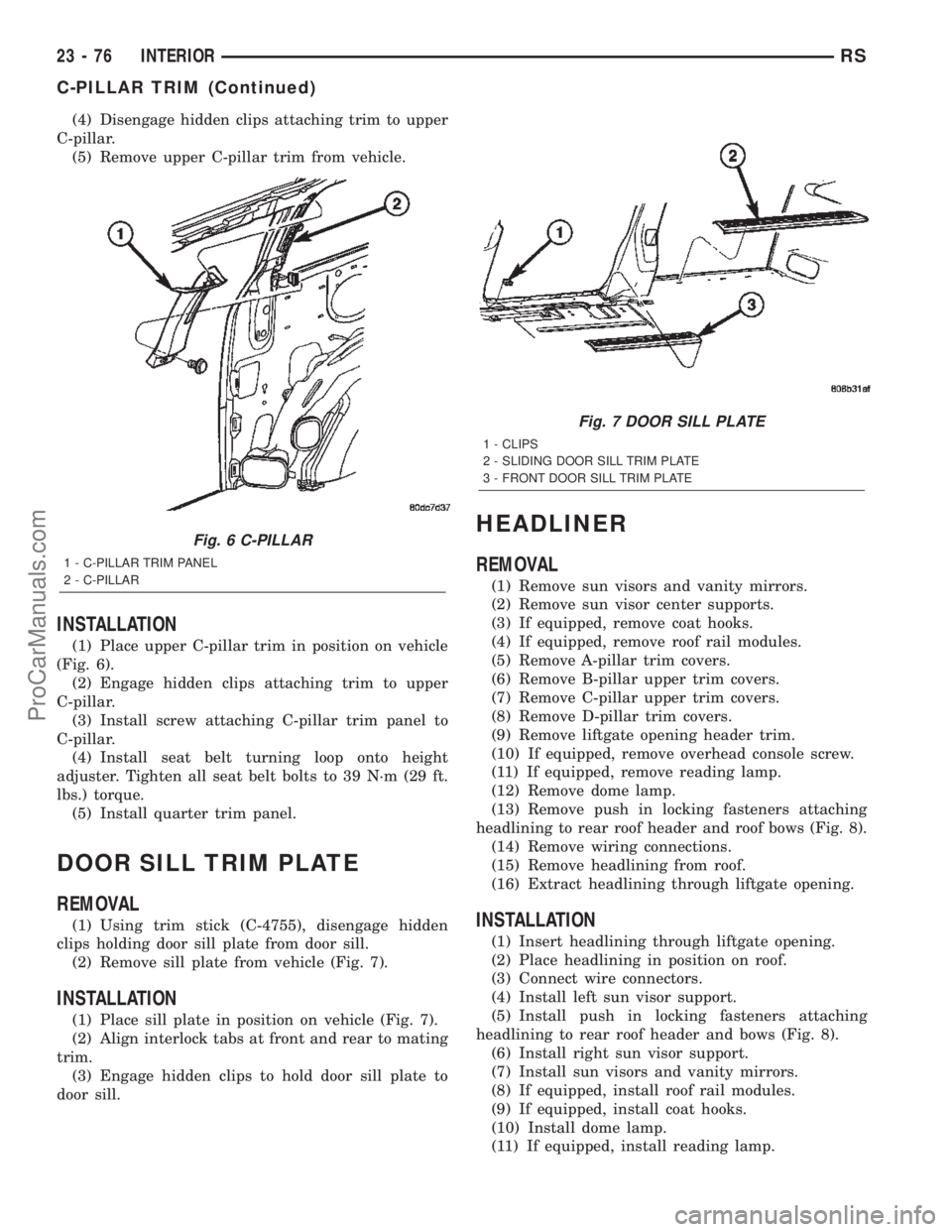
(1) Place upper C-pillar trim in position on vehicle
(Fig. 6).
(2) Engage hidden clips attaching trim to upper
C-pillar.
(3) Install screw attaching C-pillar trim panel to
C-pillar.
(4) Install seat belt turning loop onto height
adjuster. Tighten all seat belt bolts to 39 N´m (29 ft.
lbs.) torque.
(5) Install quarter trim panel.
DOOR SILL TRIM PLATE
REMOVAL
(1) Using trim stick (C-4755), disengage hidden
clips holding door sill plate from door sill.
(2) Remove sill plate from vehicle (Fig. 7).
INSTALLATION
(1) Place sill plate in position on vehicle (Fig. 7).
(2) Align interlock tabs at front and rear to mating
trim.
(3) Engage hidden clips to hold door sill plate to
door sill.
HEADLINER
REMOVAL
(1) Remove sun visors and vanity mirrors.
(2) Remove sun visor center supports.
(3) If equipped, remove coat hooks.
(4) If equipped, remove roof rail modules.
(5) Remove A-pillar trim covers.
(6) Remove B-pillar upper trim covers.
(7) Remove C-pillar upper trim covers.
(8) Remove D-pillar trim covers.
(9) Remove liftgate opening header trim.
(10) If equipped, remove overhead console screw.
(11) If equipped, remove reading lamp.
(12) Remove dome lamp.
(13) Remove push in locking fasteners attaching
headlining to rear roof header and roof bows (Fig. 8).
(14) Remove wiring connections.
(15) Remove headlining from roof.
(16) Extract headlining through liftgate opening.
INSTALLATION
(1) Insert headlining through liftgate opening.
(2) Place headlining in position on roof.
(3) Connect wire connectors.
(4) Install left sun visor support.
(5) Install push in locking fasteners attaching
headlining to rear roof header and bows (Fig. 8).
(6) Install right sun visor support.
(7) Install sun visors and vanity mirrors.
(8) If equipped, install roof rail modules.
(9) If equipped, install coat hooks.
(10) Install dome lamp.
(11) If equipped, install reading lamp.
Fig. 6 C-PILLAR
1 - C-PILLAR TRIM PANEL
2 - C-PILLAR
Fig. 7 DOOR SILL PLATE
1 - CLIPS
2 - SLIDING DOOR SILL TRIM PLATE
3 - FRONT DOOR SILL TRIM PLATE
23 - 76 INTERIORRS
C-PILLAR TRIM (Continued)
ProCarManuals.com