2002 CHRYSLER TOWN AND COUNTRY rear gate
[x] Cancel search: rear gatePage 2139 of 2399

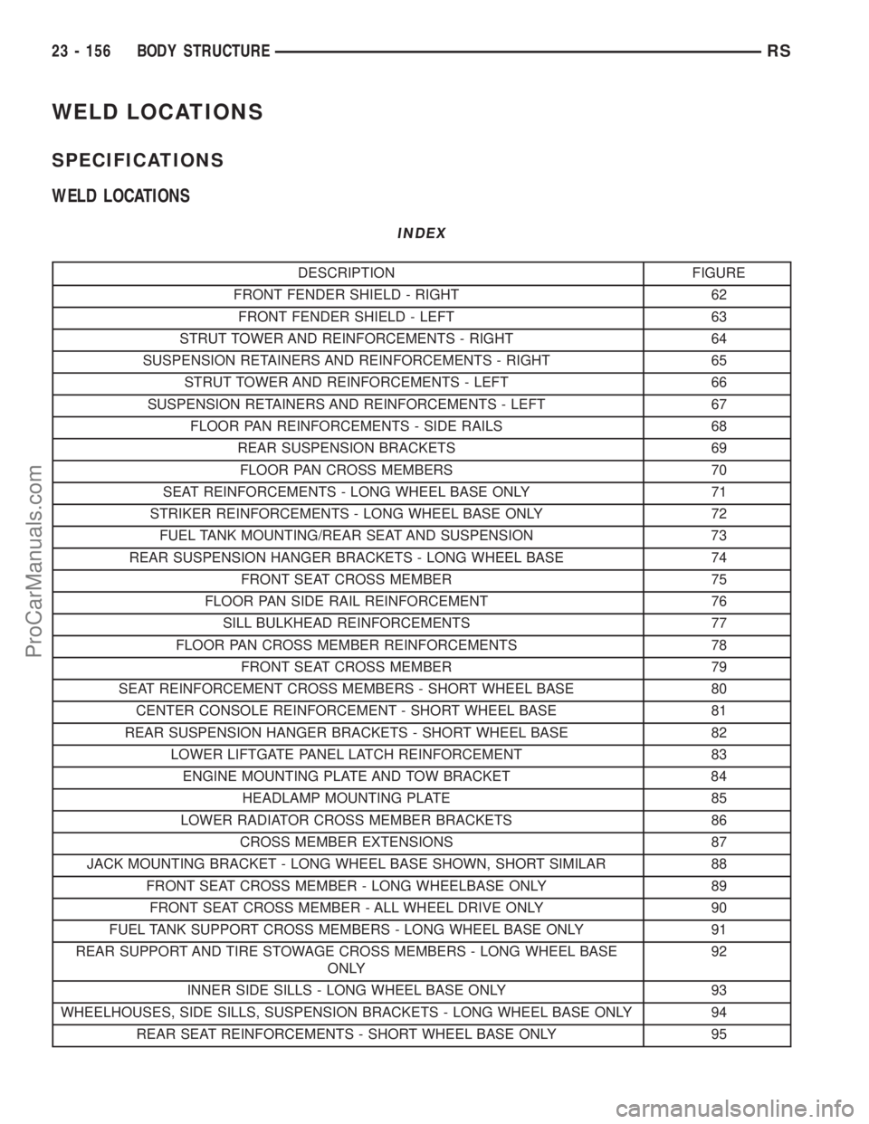
WELD LOCATIONS
SPECIFICATIONS
WELD LOCATIONS
INDEX
DESCRIPTION FIGURE
FRONT FENDER SHIELD - RIGHT 62
FRONT FENDER SHIELD - LEFT 63
STRUT TOWER AND REINFORCEMENTS - RIGHT 64
SUSPENSION RETAINERS AND REINFORCEMENTS - RIGHT 65
STRUT TOWER AND REINFORCEMENTS - LEFT 66
SUSPENSION RETAINERS AND REINFORCEMENTS - LEFT 67
FLOOR PAN REINFORCEMENTS - SIDE RAILS 68
REAR SUSPENSION BRACKETS 69
FLOOR PAN CROSS MEMBERS 70
SEAT REINFORCEMENTS - LONG WHEEL BASE ONLY 71
STRIKER REINFORCEMENTS - LONG WHEEL BASE ONLY 72
FUEL TANK MOUNTING/REAR SEAT AND SUSPENSION 73
REAR SUSPENSION HANGER BRACKETS - LONG WHEEL BASE 74
FRONT SEAT CROSS MEMBER 75
FLOOR PAN SIDE RAIL REINFORCEMENT 76
SILL BULKHEAD REINFORCEMENTS 77
FLOOR PAN CROSS MEMBER REINFORCEMENTS 78
FRONT SEAT CROSS MEMBER 79
SEAT REINFORCEMENT CROSS MEMBERS - SHORT WHEEL BASE 80
CENTER CONSOLE REINFORCEMENT - SHORT WHEEL BASE 81
REAR SUSPENSION HANGER BRACKETS - SHORT WHEEL BASE 82
LOWER LIFTGATE PANEL LATCH REINFORCEMENT 83
ENGINE MOUNTING PLATE AND TOW BRACKET 84
HEADLAMP MOUNTING PLATE 85
LOWER RADIATOR CROSS MEMBER BRACKETS 86
CROSS MEMBER EXTENSIONS 87
JACK MOUNTING BRACKET - LONG WHEEL BASE SHOWN, SHORT SIMILAR 88
FRONT SEAT CROSS MEMBER - LONG WHEELBASE ONLY 89
FRONT SEAT CROSS MEMBER - ALL WHEEL DRIVE ONLY 90
FUEL TANK SUPPORT CROSS MEMBERS - LONG WHEEL BASE ONLY 91
REAR SUPPORT AND TIRE STOWAGE CROSS MEMBERS - LONG WHEEL BASE
ONLY92
INNER SIDE SILLS - LONG WHEEL BASE ONLY 93
WHEELHOUSES, SIDE SILLS, SUSPENSION BRACKETS - LONG WHEEL BASE ONLY 94
REAR SEAT REINFORCEMENTS - SHORT WHEEL BASE ONLY 95
23 - 156 BODY STRUCTURERS
ProCarManuals.com
Page 2141 of 2399

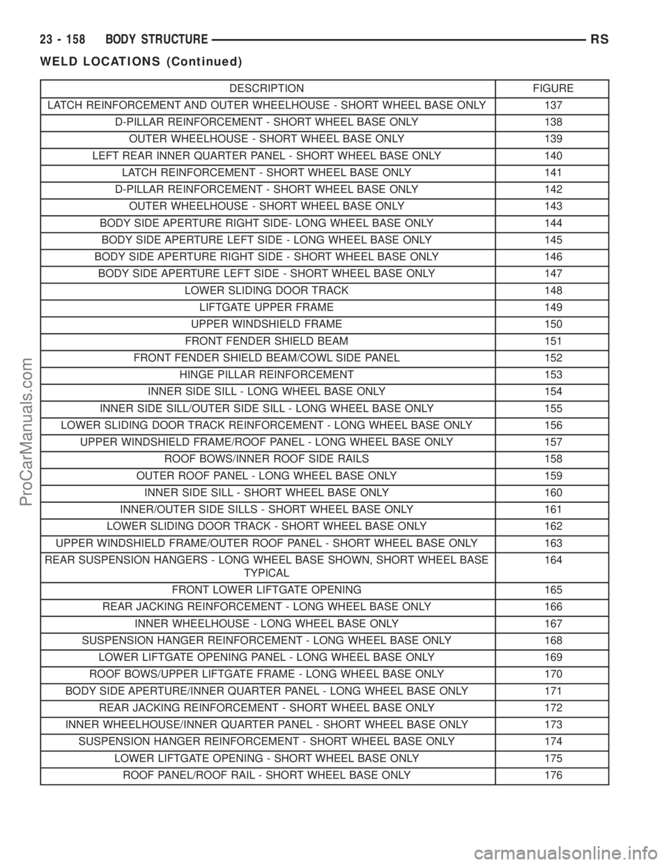
DESCRIPTION FIGURE
LATCH REINFORCEMENT AND OUTER WHEELHOUSE - SHORT WHEEL BASE ONLY 137
D-PILLAR REINFORCEMENT - SHORT WHEEL BASE ONLY 138
OUTER WHEELHOUSE - SHORT WHEEL BASE ONLY 139
LEFT REAR INNER QUARTER PANEL - SHORT WHEEL BASE ONLY 140
LATCH REINFORCEMENT - SHORT WHEEL BASE ONLY 141
D-PILLAR REINFORCEMENT - SHORT WHEEL BASE ONLY 142
OUTER WHEELHOUSE - SHORT WHEEL BASE ONLY 143
BODY SIDE APERTURE RIGHT SIDE- LONG WHEEL BASE ONLY 144
BODY SIDE APERTURE LEFT SIDE - LONG WHEEL BASE ONLY 145
BODY SIDE APERTURE RIGHT SIDE - SHORT WHEEL BASE ONLY 146
BODY SIDE APERTURE LEFT SIDE - SHORT WHEEL BASE ONLY 147
LOWER SLIDING DOOR TRACK 148
LIFTGATE UPPER FRAME 149
UPPER WINDSHIELD FRAME 150
FRONT FENDER SHIELD BEAM 151
FRONT FENDER SHIELD BEAM/COWL SIDE PANEL 152
HINGE PILLAR REINFORCEMENT 153
INNER SIDE SILL - LONG WHEEL BASE ONLY 154
INNER SIDE SILL/OUTER SIDE SILL - LONG WHEEL BASE ONLY 155
LOWER SLIDING DOOR TRACK REINFORCEMENT - LONG WHEEL BASE ONLY 156
UPPER WINDSHIELD FRAME/ROOF PANEL - LONG WHEEL BASE ONLY 157
ROOF BOWS/INNER ROOF SIDE RAILS 158
OUTER ROOF PANEL - LONG WHEEL BASE ONLY 159
INNER SIDE SILL - SHORT WHEEL BASE ONLY 160
INNER/OUTER SIDE SILLS - SHORT WHEEL BASE ONLY 161
LOWER SLIDING DOOR TRACK - SHORT WHEEL BASE ONLY 162
UPPER WINDSHIELD FRAME/OUTER ROOF PANEL - SHORT WHEEL BASE ONLY 163
REAR SUSPENSION HANGERS - LONG WHEEL BASE SHOWN, SHORT WHEEL BASE
TYPICAL164
FRONT LOWER LIFTGATE OPENING 165
REAR JACKING REINFORCEMENT - LONG WHEEL BASE ONLY 166
INNER WHEELHOUSE - LONG WHEEL BASE ONLY 167
SUSPENSION HANGER REINFORCEMENT - LONG WHEEL BASE ONLY 168
LOWER LIFTGATE OPENING PANEL - LONG WHEEL BASE ONLY 169
ROOF BOWS/UPPER LIFTGATE FRAME - LONG WHEEL BASE ONLY 170
BODY SIDE APERTURE/INNER QUARTER PANEL - LONG WHEEL BASE ONLY 171
REAR JACKING REINFORCEMENT - SHORT WHEEL BASE ONLY 172
INNER WHEELHOUSE/INNER QUARTER PANEL - SHORT WHEEL BASE ONLY 173
SUSPENSION HANGER REINFORCEMENT - SHORT WHEEL BASE ONLY 174
LOWER LIFTGATE OPENING - SHORT WHEEL BASE ONLY 175
ROOF PANEL/ROOF RAIL - SHORT WHEEL BASE ONLY 176
23 - 158 BODY STRUCTURERS
WELD LOCATIONS (Continued)
ProCarManuals.com
Page 2232 of 2399

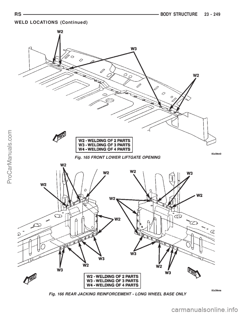
Fig. 165 FRONT LOWER LIFTGATE OPENING
Fig. 166 REAR JACKING REINFORCEMENT - LONG WHEEL BASE ONLY
RSBODY STRUCTURE23 - 249
WELD LOCATIONS (Continued)
ProCarManuals.com
Page 2245 of 2399

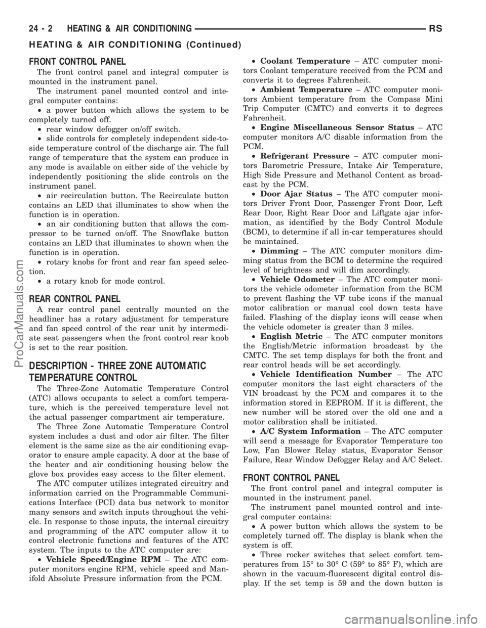
FRONT CONTROL PANEL
The front control panel and integral computer is
mounted in the instrument panel.
The instrument panel mounted control and inte-
gral computer contains:
²a power button which allows the system to be
completely turned off.
²rear window defogger on/off switch.
²slide controls for completely independent side-to-
side temperature control of the discharge air. The full
range of temperature that the system can produce in
any mode is available on either side of the vehicle by
independently positioning the slide controls on the
instrument panel.
²air recirculation button. The Recirculate button
contains an LED that illuminates to show when the
function is in operation.
²an air conditioning button that allows the com-
pressor to be turned on/off. The Snowflake button
contains an LED that illuminates to shown when the
function is in operation.
²rotary knobs for front and rear fan speed selec-
tion.
²a rotary knob for mode control.
REAR CONTROL PANEL
A rear control panel centrally mounted on the
headliner has a rotary adjustment for temperature
and fan speed control of the rear unit by intermedi-
ate seat passengers when the front control rear knob
is set to the rear position.
DESCRIPTION - THREE ZONE AUTOMATIC
TEMPERATURE CONTROL
The Three-Zone Automatic Temperature Control
(ATC) allows occupants to select a comfort tempera-
ture, which is the perceived temperature level not
the actual passenger compartment air temperature.
The Three Zone Automatic Temperature Control
system includes a dust and odor air filter. The filter
element is the same size as the air conditioning evap-
orator to ensure ample capacity. A door at the base of
the heater and air conditioning housing below the
glove box provides easy access to the filter element.
The ATC computer utilizes integrated circuitry and
information carried on the Programmable Communi-
cations Interface (PCI) data bus network to monitor
many sensors and switch inputs throughout the vehi-
cle. In response to those inputs, the internal circuitry
and programming of the ATC computer allow it to
control electronic functions and features of the ATC
system. The inputs to the ATC computer are:
²Vehicle Speed/Engine RPM± The ATC com-
puter monitors engine RPM, vehicle speed and Man-
ifold Absolute Pressure information from the PCM.²Coolant Temperature± ATC computer moni-
tors Coolant temperature received from the PCM and
converts it to degrees Fahrenheit.
²Ambient Temperature± ATC computer moni-
tors Ambient temperature from the Compass Mini
Trip Computer (CMTC) and converts it to degrees
Fahrenheit.
²Engine Miscellaneous Sensor Status±ATC
computer monitors A/C disable information from the
PCM.
²Refrigerant Pressure± ATC computer moni-
tors Barometric Pressure, Intake Air Temperature,
High Side Pressure and Methanol Content as broad-
cast by the PCM.
²Door Ajar Status± The ATC computer moni-
tors Driver Front Door, Passenger Front Door, Left
Rear Door, Right Rear Door and Liftgate ajar infor-
mation, as identified by the Body Control Module
(BCM), to determine if all in-car temperatures should
be maintained.
²Dimming± The ATC computer monitors dim-
ming status from the BCM to determine the required
level of brightness and will dim accordingly.
²Vehicle Odometer± The ATC computer moni-
tors the vehicle odometer information from the BCM
to prevent flashing the VF tube icons if the manual
motor calibration or manual cool down tests have
failed. Flashing of the display icons will cease when
the vehicle odometer is greater than 3 miles.
²English Metric± The ATC computer monitors
the English/Metric information broadcast by the
CMTC. The set temp displays for both the front and
rear control heads will be set accordingly.
²Vehicle Identification Number± The ATC
computer monitors the last eight characters of the
VIN broadcast by the PCM and compares it to the
information stored in EEPROM. If it is different, the
new number will be stored over the old one and a
motor calibration shall be initiated.
²A/C System Information± The ATC computer
will send a message for Evaporator Temperature too
Low, Fan Blower Relay status, Evaporator Sensor
Failure, Rear Window Defogger Relay and A/C Select.
FRONT CONTROL PANEL
The front control panel and integral computer is
mounted in the instrument panel.
The instrument panel mounted control and inte-
gral computer contains:
²A power button which allows the system to be
completely turned off. The display is blank when the
system is off.
²Three rocker switches that select comfort tem-
peratures from 15É to 30É C (59É to 85É F), which are
shown in the vacuum-fluorescent digital control dis-
play. If the set temp is 59 and the down button is
24 - 2 HEATING & AIR CONDITIONINGRS
HEATING & AIR CONDITIONING (Continued)
ProCarManuals.com