2002 CHRYSLER TOWN AND COUNTRY motor mount
[x] Cancel search: motor mountPage 2267 of 2399
INFRARED TEMPERATURE
SENSOR
DESCRIPTION
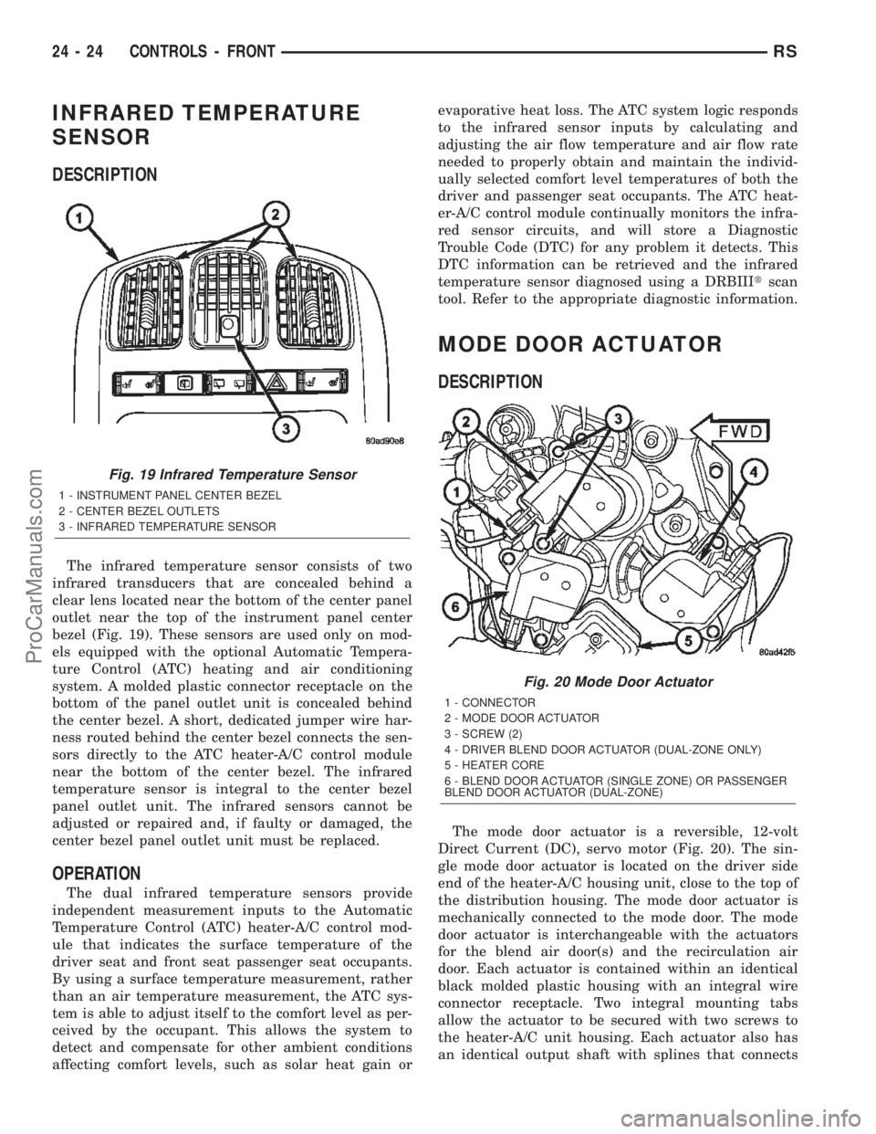
The infrared temperature sensor consists of two
infrared transducers that are concealed behind a
clear lens located near the bottom of the center panel
outlet near the top of the instrument panel center
bezel (Fig. 19). These sensors are used only on mod-
els equipped with the optional Automatic Tempera-
ture Control (ATC) heating and air conditioning
system. A molded plastic connector receptacle on the
bottom of the panel outlet unit is concealed behind
the center bezel. A short, dedicated jumper wire har-
ness routed behind the center bezel connects the sen-
sors directly to the ATC heater-A/C control module
near the bottom of the center bezel. The infrared
temperature sensor is integral to the center bezel
panel outlet unit. The infrared sensors cannot be
adjusted or repaired and, if faulty or damaged, the
center bezel panel outlet unit must be replaced.
OPERATION
The dual infrared temperature sensors provide
independent measurement inputs to the Automatic
Temperature Control (ATC) heater-A/C control mod-
ule that indicates the surface temperature of the
driver seat and front seat passenger seat occupants.
By using a surface temperature measurement, rather
than an air temperature measurement, the ATC sys-
tem is able to adjust itself to the comfort level as per-
ceived by the occupant. This allows the system to
detect and compensate for other ambient conditions
affecting comfort levels, such as solar heat gain orevaporative heat loss. The ATC system logic responds
to the infrared sensor inputs by calculating and
adjusting the air flow temperature and air flow rate
needed to properly obtain and maintain the individ-
ually selected comfort level temperatures of both the
driver and passenger seat occupants. The ATC heat-
er-A/C control module continually monitors the infra-
red sensor circuits, and will store a Diagnostic
Trouble Code (DTC) for any problem it detects. This
DTC information can be retrieved and the infrared
temperature sensor diagnosed using a DRBIIItscan
tool. Refer to the appropriate diagnostic information.
MODE DOOR ACTUATOR
DESCRIPTION
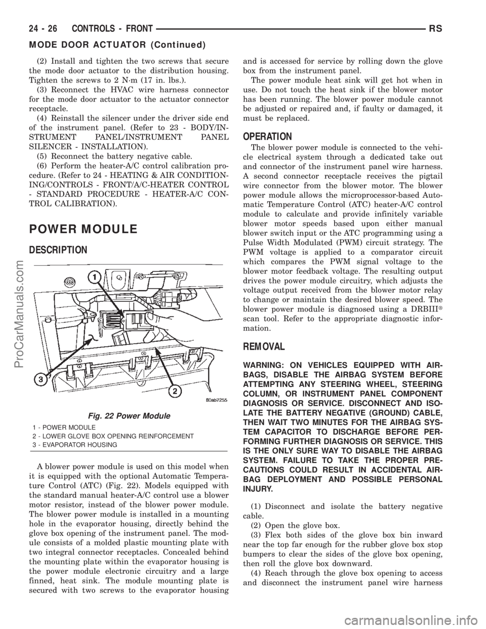
The mode door actuator is a reversible, 12-volt
Direct Current (DC), servo motor (Fig. 20). The sin-
gle mode door actuator is located on the driver side
end of the heater-A/C housing unit, close to the top of
the distribution housing. The mode door actuator is
mechanically connected to the mode door. The mode
door actuator is interchangeable with the actuators
for the blend air door(s) and the recirculation air
door. Each actuator is contained within an identical
black molded plastic housing with an integral wire
connector receptacle. Two integral mounting tabs
allow the actuator to be secured with two screws to
the heater-A/C unit housing. Each actuator also has
an identical output shaft with splines that connects
Fig. 19 Infrared Temperature Sensor
1 - INSTRUMENT PANEL CENTER BEZEL
2 - CENTER BEZEL OUTLETS
3 - INFRARED TEMPERATURE SENSOR
Fig. 20 Mode Door Actuator
1 - CONNECTOR
2 - MODE DOOR ACTUATOR
3 - SCREW (2)
4 - DRIVER BLEND DOOR ACTUATOR (DUAL-ZONE ONLY)
5 - HEATER CORE
6 - BLEND DOOR ACTUATOR (SINGLE ZONE) OR PASSENGER
BLEND DOOR ACTUATOR (DUAL-ZONE)
24 - 24 CONTROLS - FRONTRS
ProCarManuals.com
Page 2269 of 2399
(2) Install and tighten the two screws that secure
the mode door actuator to the distribution housing.
Tighten the screws to 2 N´m (17 in. lbs.).
(3) Reconnect the HVAC wire harness connector
for the mode door actuator to the actuator connector
receptacle.
(4) Reinstall the silencer under the driver side end
of the instrument panel. (Refer to 23 - BODY/IN-
STRUMENT PANEL/INSTRUMENT PANEL
SILENCER - INSTALLATION).
(5) Reconnect the battery negative cable.
(6) Perform the heater-A/C control calibration pro-
cedure. (Refer to 24 - HEATING & AIR CONDITION-
ING/CONTROLS - FRONT/A/C-HEATER CONTROL
- STANDARD PROCEDURE - HEATER-A/C CON-
TROL CALIBRATION).
POWER MODULE
DESCRIPTION
A blower power module is used on this model when
it is equipped with the optional Automatic Tempera-
ture Control (ATC) (Fig. 22). Models equipped with
the standard manual heater-A/C control use a blower
motor resistor, instead of the blower power module.
The blower power module is installed in a mounting
hole in the evaporator housing, directly behind the
glove box opening of the instrument panel. The mod-
ule consists of a molded plastic mounting plate with
two integral connector receptacles. Concealed behind
the mounting plate within the evaporator housing is
the power module electronic circuitry and a large
finned, heat sink. The module mounting plate is
secured with two screws to the evaporator housingand is accessed for service by rolling down the glove
box from the instrument panel.
The power module heat sink will get hot when in
use. Do not touch the heat sink if the blower motor
has been running. The blower power module cannot
be adjusted or repaired and, if faulty or damaged, it
must be replaced.
OPERATION
The blower power module is connected to the vehi-
cle electrical system through a dedicated take out
and connector of the instrument panel wire harness.
A second connector receptacle receives the pigtail
wire connector from the blower motor. The blower
power module allows the microprocessor-based Auto-
matic Temperature Control (ATC) heater-A/C control
module to calculate and provide infinitely variable
blower motor speeds based upon either manual
blower switch input or the ATC programming using a
Pulse Width Modulated (PWM) circuit strategy. The
PWM voltage is applied to a comparator circuit
which compares the PWM signal voltage to the
blower motor feedback voltage. The resulting output
drives the power module circuitry, which adjusts the
voltage output received from the blower motor relay
to change or maintain the desired blower speed. The
blower power module is diagnosed using a DRBIIIt
scan tool. Refer to the appropriate diagnostic infor-
mation.
REMOVAL
WARNING: ON VEHICLES EQUIPPED WITH AIR-
BAGS, DISABLE THE AIRBAG SYSTEM BEFORE
ATTEMPTING ANY STEERING WHEEL, STEERING
COLUMN, OR INSTRUMENT PANEL COMPONENT
DIAGNOSIS OR SERVICE. DISCONNECT AND ISO-
LATE THE BATTERY NEGATIVE (GROUND) CABLE,
THEN WAIT TWO MINUTES FOR THE AIRBAG SYS-
TEM CAPACITOR TO DISCHARGE BEFORE PER-
FORMING FURTHER DIAGNOSIS OR SERVICE. THIS
IS THE ONLY SURE WAY TO DISABLE THE AIRBAG
SYSTEM. FAILURE TO TAKE THE PROPER PRE-
CAUTIONS COULD RESULT IN ACCIDENTAL AIR-
BAG DEPLOYMENT AND POSSIBLE PERSONAL
INJURY.
(1) Disconnect and isolate the battery negative
cable.
(2) Open the glove box.
(3) Flex both sides of the glove box bin inward
near the top far enough for the rubber glove box stop
bumpers to clear the sides of the glove box opening,
then roll the glove box downward.
(4) Reach through the glove box opening to access
and disconnect the instrument panel wire harness
Fig. 22 Power Module
1 - POWER MODULE
2 - LOWER GLOVE BOX OPENING REINFORCEMENT
3 - EVAPORATOR HOUSING
24 - 26 CONTROLS - FRONTRS
MODE DOOR ACTUATOR (Continued)
ProCarManuals.com
Page 2270 of 2399
connector for the power module from the module con-
nector receptacle.
(5) Reach through the glove box opening to access
and disconnect the blower motor pigtail wire connec-
tor from the power module connector receptacle.
(6) Remove the two screws that secure the power
module to the evaporator housing.
(7) Remove the power module from the evaporator
housing.
INSTALLATION
WARNING: ON VEHICLES EQUIPPED WITH AIR-
BAGS, DISABLE THE AIRBAG SYSTEM BEFORE
ATTEMPTING ANY STEERING WHEEL, STEERING
COLUMN, OR INSTRUMENT PANEL COMPONENT
DIAGNOSIS OR SERVICE. DISCONNECT AND ISO-
LATE THE BATTERY NEGATIVE (GROUND) CABLE,
THEN WAIT TWO MINUTES FOR THE AIRBAG SYS-
TEM CAPACITOR TO DISCHARGE BEFORE PER-
FORMING FURTHER DIAGNOSIS OR SERVICE. THIS
IS THE ONLY SURE WAY TO DISABLE THE AIRBAG
SYSTEM. FAILURE TO TAKE THE PROPER PRE-
CAUTIONS COULD RESULT IN ACCIDENTAL AIR-
BAG DEPLOYMENT AND POSSIBLE PERSONAL
INJURY.
(1) Position the power module into the evaporator
housing.
(2) Install and tighten the two screws that secure
the power module to the evaporator housing. Tighten
the screws to 2 N´m (18 in. lbs.).
(3) Reconnect the blower motor pigtail wire con-
nector to the power module connector receptacle.
(4) Reconnect the instrument panel wire harness
connector for the power module to the module con-
nector receptacle.
(5) Flex both sides of the glove box bin inward
near the top far enough for the rubber glove box stop
bumpers to clear the sides of the glove box opening,
then roll the glove box upward.
(6) Close and latch the glove box.
(7) Reconnect the battery negative cable.
RECIRCULATION DOOR
ACTUATOR
DESCRIPTION
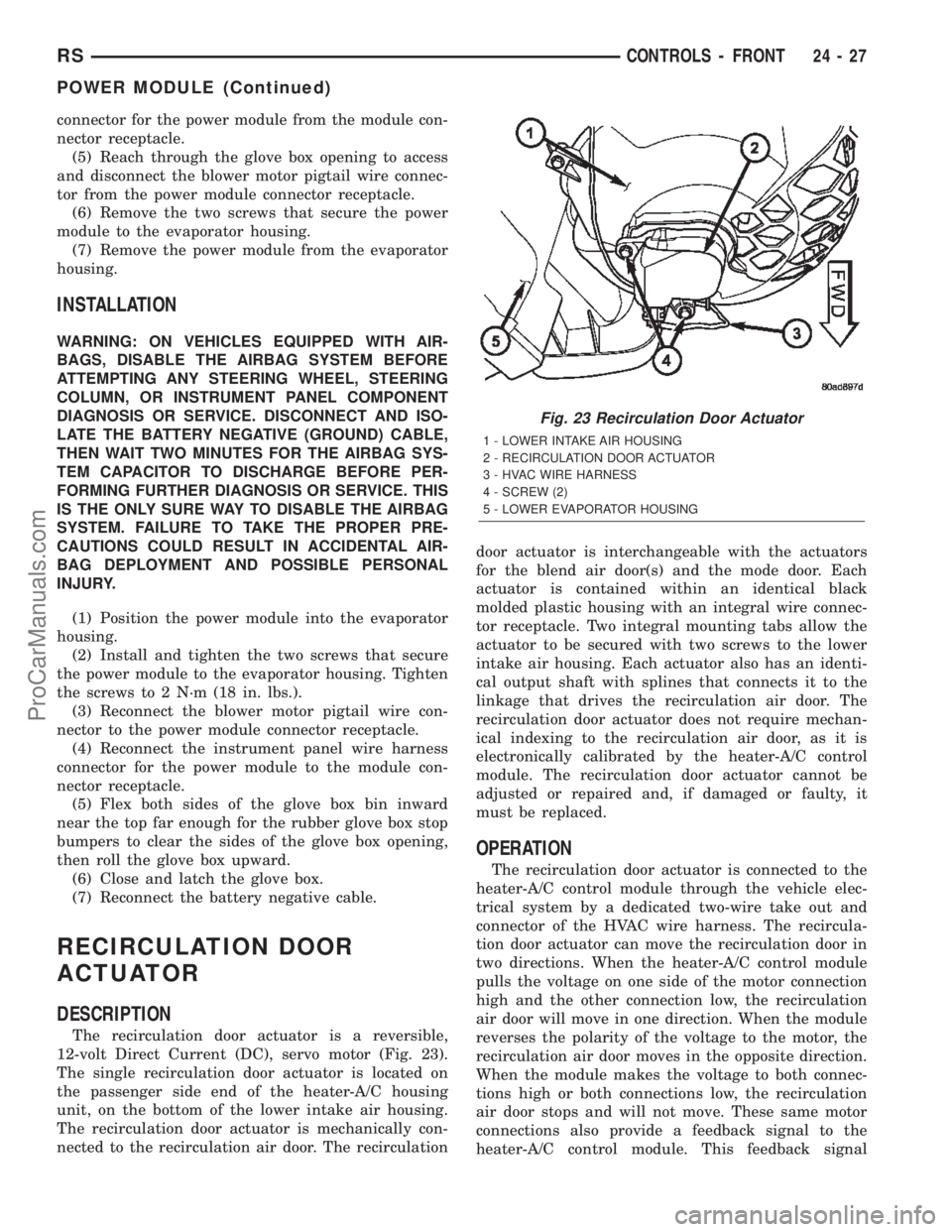
The recirculation door actuator is a reversible,
12-volt Direct Current (DC), servo motor (Fig. 23).
The single recirculation door actuator is located on
the passenger side end of the heater-A/C housing
unit, on the bottom of the lower intake air housing.
The recirculation door actuator is mechanically con-
nected to the recirculation air door. The recirculationdoor actuator is interchangeable with the actuators
for the blend air door(s) and the mode door. Each
actuator is contained within an identical black
molded plastic housing with an integral wire connec-
tor receptacle. Two integral mounting tabs allow the
actuator to be secured with two screws to the lower
intake air housing. Each actuator also has an identi-
cal output shaft with splines that connects it to the
linkage that drives the recirculation air door. The
recirculation door actuator does not require mechan-
ical indexing to the recirculation air door, as it is
electronically calibrated by the heater-A/C control
module. The recirculation door actuator cannot be
adjusted or repaired and, if damaged or faulty, it
must be replaced.
OPERATION
The recirculation door actuator is connected to the
heater-A/C control module through the vehicle elec-
trical system by a dedicated two-wire take out and
connector of the HVAC wire harness. The recircula-
tion door actuator can move the recirculation door in
two directions. When the heater-A/C control module
pulls the voltage on one side of the motor connection
high and the other connection low, the recirculation
air door will move in one direction. When the module
reverses the polarity of the voltage to the motor, the
recirculation air door moves in the opposite direction.
When the module makes the voltage to both connec-
tions high or both connections low, the recirculation
air door stops and will not move. These same motor
connections also provide a feedback signal to the
heater-A/C control module. This feedback signal
Fig. 23 Recirculation Door Actuator
1 - LOWER INTAKE AIR HOUSING
2 - RECIRCULATION DOOR ACTUATOR
3 - HVAC WIRE HARNESS
4 - SCREW (2)
5 - LOWER EVAPORATOR HOUSING
RSCONTROLS - FRONT24-27
POWER MODULE (Continued)
ProCarManuals.com
Page 2273 of 2399
bezel with the snap clip receptacles on the retainer
above the headliner.
(7) Using hand pressure, press the top edge of the
rear heater-A/C control bezel upward until the two
snap clips are fully seated in their receptacles.
(8) Reconnect the battery negative cable.
(9) Using the DRB-IIItreset the Rear Tempera-
ture Selector calibration values.
(10) Verify that the Actuator Calibration of the
Front Control has passed. If an Actuator Calibration
has not passed correct any errors before proceeding
further.
(11) Rotate the Rear Temperature Selector counter
clockwise to the Cold Position, allow the Selector to
remain in the Cold Position for 5 seconds.
(12) Rotate the Rear Temperature Selector Clock-
wise to the Hot Position, allow the Selector to remain
in the Cold Position for 5 seconds.
(13) calibration is now complete.
BLEND DOOR ACTUATOR
DESCRIPTION
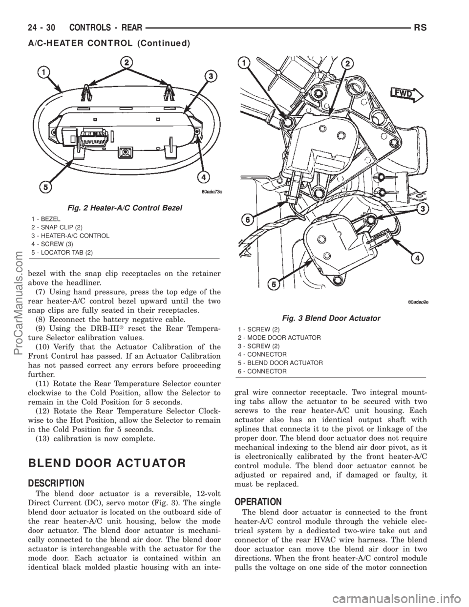
The blend door actuator is a reversible, 12-volt
Direct Current (DC), servo motor (Fig. 3). The single
blend door actuator is located on the outboard side of
the rear heater-A/C unit housing, below the mode
door actuator. The blend door actuator is mechani-
cally connected to the blend air door. The blend door
actuator is interchangeable with the actuator for the
mode door. Each actuator is contained within an
identical black molded plastic housing with an inte-gral wire connector receptacle. Two integral mount-
ing tabs allow the actuator to be secured with two
screws to the rear heater-A/C unit housing. Each
actuator also has an identical output shaft with
splines that connects it to the pivot or linkage of the
proper door. The blend door actuator does not require
mechanical indexing to the blend air door pivot, as it
is electronically calibrated by the front heater-A/C
control module. The blend door actuator cannot be
adjusted or repaired and, if damaged or faulty, it
must be replaced.
OPERATION
The blend door actuator is connected to the front
heater-A/C control module through the vehicle elec-
trical system by a dedicated two-wire take out and
connector of the rear HVAC wire harness. The blend
door actuator can move the blend air door in two
directions. When the front heater-A/C control module
pulls the voltage on one side of the motor connection
Fig. 2 Heater-A/C Control Bezel
1 - BEZEL
2 - SNAP CLIP (2)
3 - HEATER-A/C CONTROL
4 - SCREW (3)
5 - LOCATOR TAB (2)
Fig. 3 Blend Door Actuator
1 - SCREW (2)
2 - MODE DOOR ACTUATOR
3 - SCREW (2)
4 - CONNECTOR
5 - BLEND DOOR ACTUATOR
6 - CONNECTOR
24 - 30 CONTROLS - REARRS
A/C-HEATER CONTROL (Continued)
ProCarManuals.com
Page 2277 of 2399
(3) See the fuse and relay layout map molded into
the inner surface of the IPM cover for rear blower
motor relay identification and location.
(4) Remove the rear blower motor relay from the
IPM.
INSTALLATION
(1) See the fuse and relay layout map molded into
the inner surface of the Intelligent Power Module
(IPM) cover for rear blower motor relay identification
and location.
(2) Position the rear blower motor relay to the
proper receptacle in the IPM.
(3) Align the rear blower motor relay terminals
with the terminal cavities in the IPM relay recepta-
cle.
(4) Push down firmly on the rear blower motor
relay until the terminals are fully seated in the ter-
minal cavities in the IPM receptacle.
(5) Install and latch the cover onto the IPM.
(6) Reconnect the battery negative cable.
BLOWER MOTOR RESISTOR
DESCRIPTION
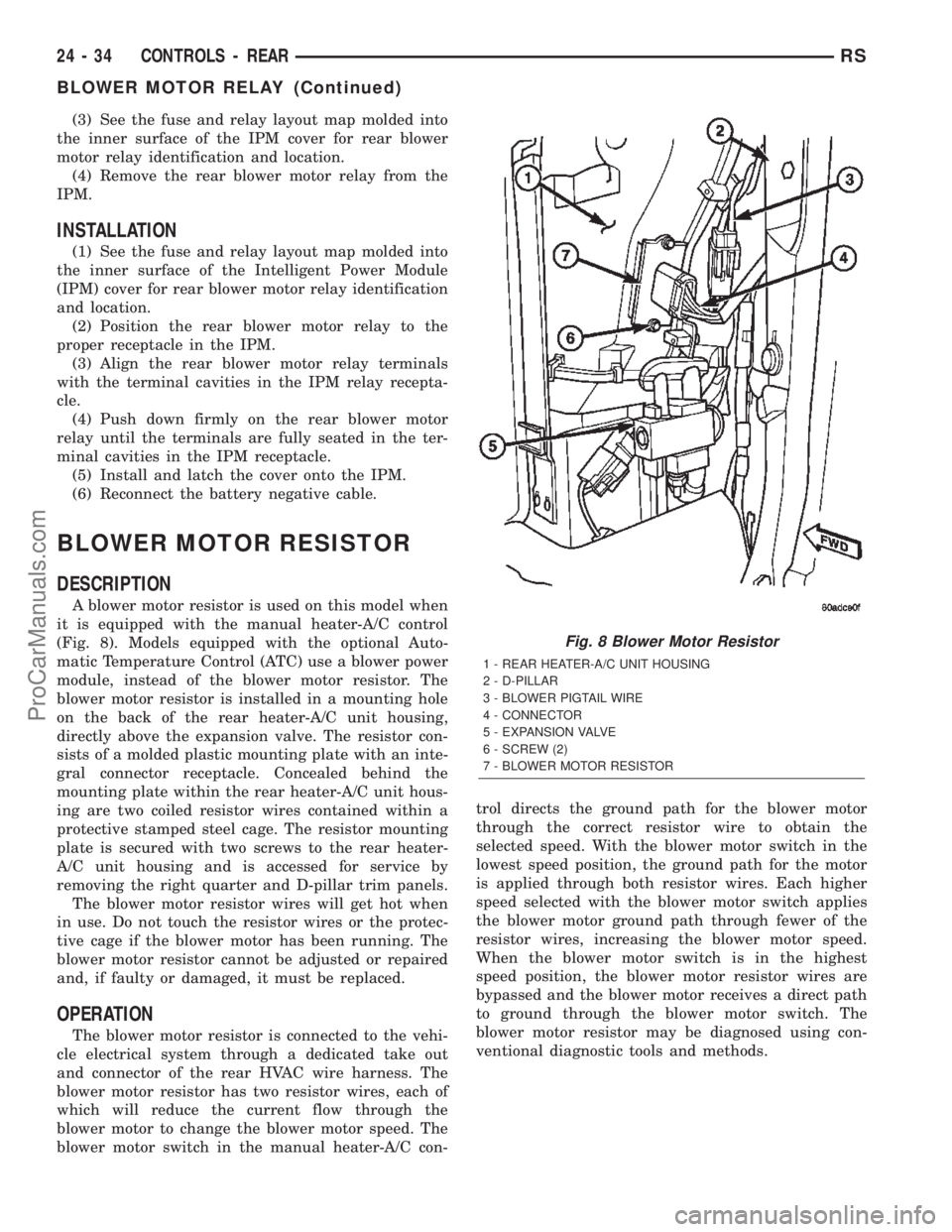
A blower motor resistor is used on this model when
it is equipped with the manual heater-A/C control
(Fig. 8). Models equipped with the optional Auto-
matic Temperature Control (ATC) use a blower power
module, instead of the blower motor resistor. The
blower motor resistor is installed in a mounting hole
on the back of the rear heater-A/C unit housing,
directly above the expansion valve. The resistor con-
sists of a molded plastic mounting plate with an inte-
gral connector receptacle. Concealed behind the
mounting plate within the rear heater-A/C unit hous-
ing are two coiled resistor wires contained within a
protective stamped steel cage. The resistor mounting
plate is secured with two screws to the rear heater-
A/C unit housing and is accessed for service by
removing the right quarter and D-pillar trim panels.
The blower motor resistor wires will get hot when
in use. Do not touch the resistor wires or the protec-
tive cage if the blower motor has been running. The
blower motor resistor cannot be adjusted or repaired
and, if faulty or damaged, it must be replaced.
OPERATION
The blower motor resistor is connected to the vehi-
cle electrical system through a dedicated take out
and connector of the rear HVAC wire harness. The
blower motor resistor has two resistor wires, each of
which will reduce the current flow through the
blower motor to change the blower motor speed. The
blower motor switch in the manual heater-A/C con-trol directs the ground path for the blower motor
through the correct resistor wire to obtain the
selected speed. With the blower motor switch in the
lowest speed position, the ground path for the motor
is applied through both resistor wires. Each higher
speed selected with the blower motor switch applies
the blower motor ground path through fewer of the
resistor wires, increasing the blower motor speed.
When the blower motor switch is in the highest
speed position, the blower motor resistor wires are
bypassed and the blower motor receives a direct path
to ground through the blower motor switch. The
blower motor resistor may be diagnosed using con-
ventional diagnostic tools and methods.
Fig. 8 Blower Motor Resistor
1 - REAR HEATER-A/C UNIT HOUSING
2 - D-PILLAR
3 - BLOWER PIGTAIL WIRE
4 - CONNECTOR
5 - EXPANSION VALVE
6 - SCREW (2)
7 - BLOWER MOTOR RESISTOR
24 - 34 CONTROLS - REARRS
BLOWER MOTOR RELAY (Continued)
ProCarManuals.com
Page 2280 of 2399
(10) Remove the mode door actuator from between
the rear heater-A/C unit housing and the quarter
inner panel.
INSTALLATION
(1) Position the mode door actuator between the
rear heater-A/C unit housing and the quarter inner
panel.
(2) Reconnect the rear HVAC wire harness connec-
tor for the mode door actuator to the actuator connec-
tor receptacle.
(3) Position the mode door actuator onto the rear
heater-A/C unit housing. If necessary, rotate the
actuator slightly to align the splines on the actuator
output shaft with those in the mode door linkage.
(4) Install and tighten the two screws that secure
the mode door actuator to the rear heater-A/C unit
housing. Tighten the screws to 2 N´m (18 in. lbs.).
(5) Push the top of the rear heater-A/C unit hous-
ing back into position against the right quarter inner
panel.
(6) Install and tighten the screw that secures the
front of the rear heater-A/C unit housing to the right
quarter inner panel. Tighten the screw to 11 N´m (97
in. lbs.).
(7) Install and tighten the screw that secures the
back of the rear heater-A/C unit housing to the right
D-pillar. Tighten the screw to 11 N´m (97 in. lbs.).
(8) Install and tighten the two screws that secure
the top of the quarter trim panel attaching bracket to
the quarter inner panel. Tighten the screws to 1.7
N´m (15 in. lbs.).
(9) Reinstall the right quarter trim panel and
right D-pillar trim panel onto the quarter inner
panel. (Refer to 23 - BODY/INTERIOR/QUARTER
TRIM PANEL - INSTALLATION).
(10) Reconnect the battery negative cable.
(11) Perform the heater-A/C control calibration
procedure. (Refer to 24 - HEATING & AIR CONDI-
TIONING/CONTROLS - FRONT/A/C-HEATER CON-
TROL - STANDARD PROCEDURE - HEATER-A/C
CONTROL CALIBRATION).
POWER MODULE
DESCRIPTION
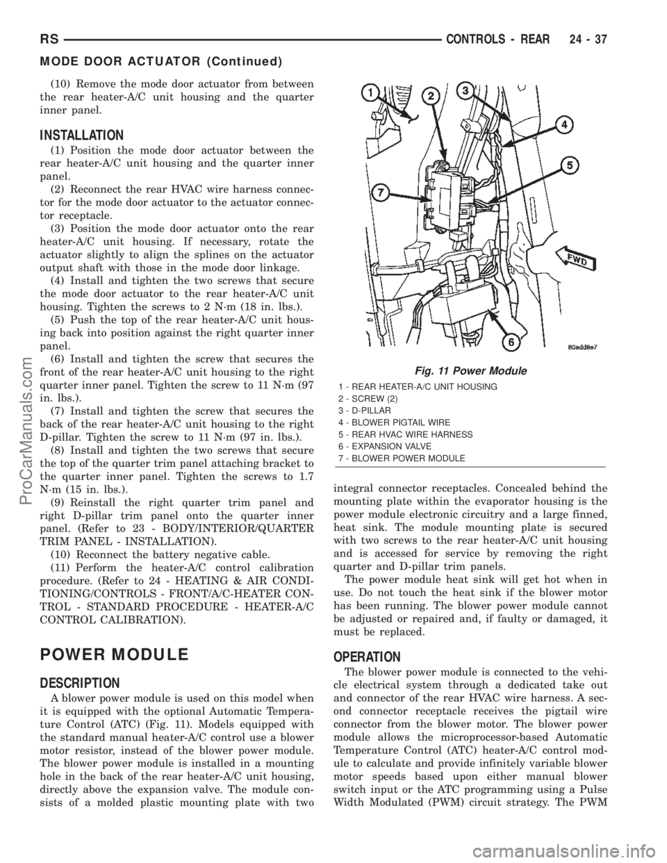
A blower power module is used on this model when
it is equipped with the optional Automatic Tempera-
ture Control (ATC) (Fig. 11). Models equipped with
the standard manual heater-A/C control use a blower
motor resistor, instead of the blower power module.
The blower power module is installed in a mounting
hole in the back of the rear heater-A/C unit housing,
directly above the expansion valve. The module con-
sists of a molded plastic mounting plate with twointegral connector receptacles. Concealed behind the
mounting plate within the evaporator housing is the
power module electronic circuitry and a large finned,
heat sink. The module mounting plate is secured
with two screws to the rear heater-A/C unit housing
and is accessed for service by removing the right
quarter and D-pillar trim panels.
The power module heat sink will get hot when in
use. Do not touch the heat sink if the blower motor
has been running. The blower power module cannot
be adjusted or repaired and, if faulty or damaged, it
must be replaced.
OPERATION
The blower power module is connected to the vehi-
cle electrical system through a dedicated take out
and connector of the rear HVAC wire harness. A sec-
ond connector receptacle receives the pigtail wire
connector from the blower motor. The blower power
module allows the microprocessor-based Automatic
Temperature Control (ATC) heater-A/C control mod-
ule to calculate and provide infinitely variable blower
motor speeds based upon either manual blower
switch input or the ATC programming using a Pulse
Width Modulated (PWM) circuit strategy. The PWM
Fig. 11 Power Module
1 - REAR HEATER-A/C UNIT HOUSING
2 - SCREW (2)
3 - D-PILLAR
4 - BLOWER PIGTAIL WIRE
5 - REAR HVAC WIRE HARNESS
6 - EXPANSION VALVE
7 - BLOWER POWER MODULE
RSCONTROLS - REAR24-37
MODE DOOR ACTUATOR (Continued)
ProCarManuals.com
Page 2286 of 2399
INSTALLATION
INSTALLATION - CENTER BEZEL OUTLETS
(1) Position the center bezel outlets and housing
onto the center bezel as a unit.
(2) Engage the retainer features on the top of the
outlet housing with their receptacles at the top of the
center bezel, then roll the bottom of the outlet hous-
ing downwards towards the center bezel.
(3) Install and tighten the three screws that secure
the bottom of the outlet housing to the center bezel.
Tighten the screws to 2 N´m (17 in. lbs.).
(4) If the vehicle is equipped with the optional
ATC system, reconnect the ATC remote infrared tem-
perature sensor jumper harness to the sensor connec-
tor receptacle located on the bottom of the center
outlet housing.
(5) Reinstall the center bezel onto the instrument
panel. (Refer to 23 - BODY/INSTRUMENT PANEL/
INSTRUMENT PANEL CENTER BEZEL - INSTAL-
LATION).
(6) Reconnect the battery negative cable.
INSTALLATION - DEMISTER OUTLET
(1) Position the demister outlet over the demister
duct opening in the instrument panel top pad.
(2) Using hand pressure, press the demister outlet
firmly and evenly into the instrument panel top pad
opening until the snap features on the outlet are
fully engaged.
INSTALLATION - FRONT DOOR REAR OUTLET
(1) Position the front door rear outlet through the
outside of the front door trim panel outlet opening.
(2) While keeping the outlet aligned with the door
duct opening behind the trim panel, use hand pres-
sure to press the outlet firmly and evenly through
the outside of the front door trim panel outlet open-
ing until the four latch features (two top and two bot-
tom) that secure the outlet to the inside of the
opening are fully engaged.
(3) Reinstall the trim panel onto the front door
inner panel. (Refer to 23 - BODY/DOOR - FRONT/
TRIM PANEL - INSTALLATION).
(4) Reconnect the battery negative cable.
INSTALLATION - INSTRUMENT PANEL OUTLET
(1) Position the instrument panel outlet into the
panel duct opening in the instrument panel top pad.
(2) Using hand pressure, press the instrument
panel outlet firmly and evenly into the instrument
panel top pad opening until the snap features on the
outlet are fully engaged.
BLOWER MOTOR
DESCRIPTION
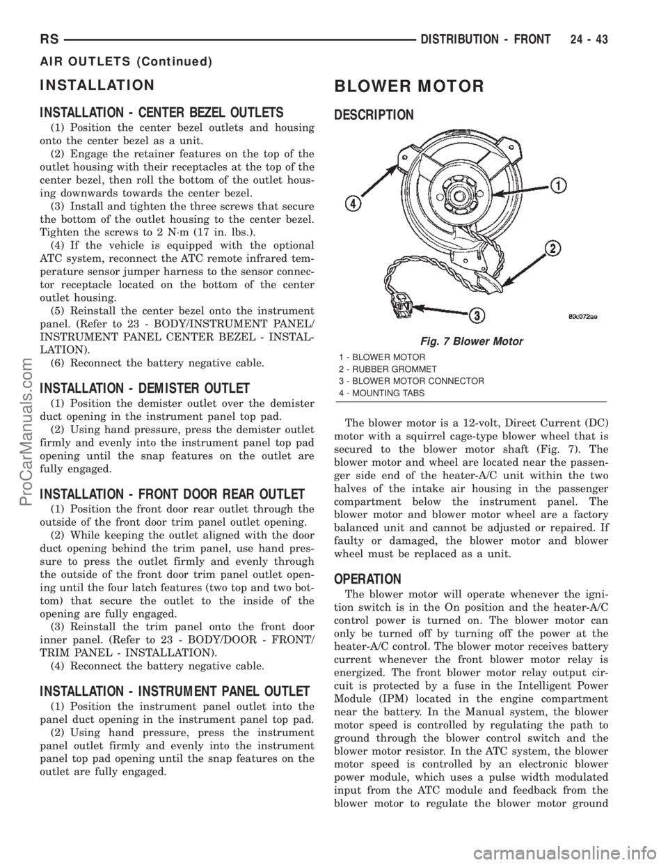
The blower motor is a 12-volt, Direct Current (DC)
motor with a squirrel cage-type blower wheel that is
secured to the blower motor shaft (Fig. 7). The
blower motor and wheel are located near the passen-
ger side end of the heater-A/C unit within the two
halves of the intake air housing in the passenger
compartment below the instrument panel. The
blower motor and blower motor wheel are a factory
balanced unit and cannot be adjusted or repaired. If
faulty or damaged, the blower motor and blower
wheel must be replaced as a unit.
OPERATION
The blower motor will operate whenever the igni-
tion switch is in the On position and the heater-A/C
control power is turned on. The blower motor can
only be turned off by turning off the power at the
heater-A/C control. The blower motor receives battery
current whenever the front blower motor relay is
energized. The front blower motor relay output cir-
cuit is protected by a fuse in the Intelligent Power
Module (IPM) located in the engine compartment
near the battery. In the Manual system, the blower
motor speed is controlled by regulating the path to
ground through the blower control switch and the
blower motor resistor. In the ATC system, the blower
motor speed is controlled by an electronic blower
power module, which uses a pulse width modulated
input from the ATC module and feedback from the
blower motor to regulate the blower motor ground
Fig. 7 Blower Motor
1 - BLOWER MOTOR
2 - RUBBER GROMMET
3 - BLOWER MOTOR CONNECTOR
4 - MOUNTING TABS
RSDISTRIBUTION - FRONT24-43
AIR OUTLETS (Continued)
ProCarManuals.com
Page 2289 of 2399
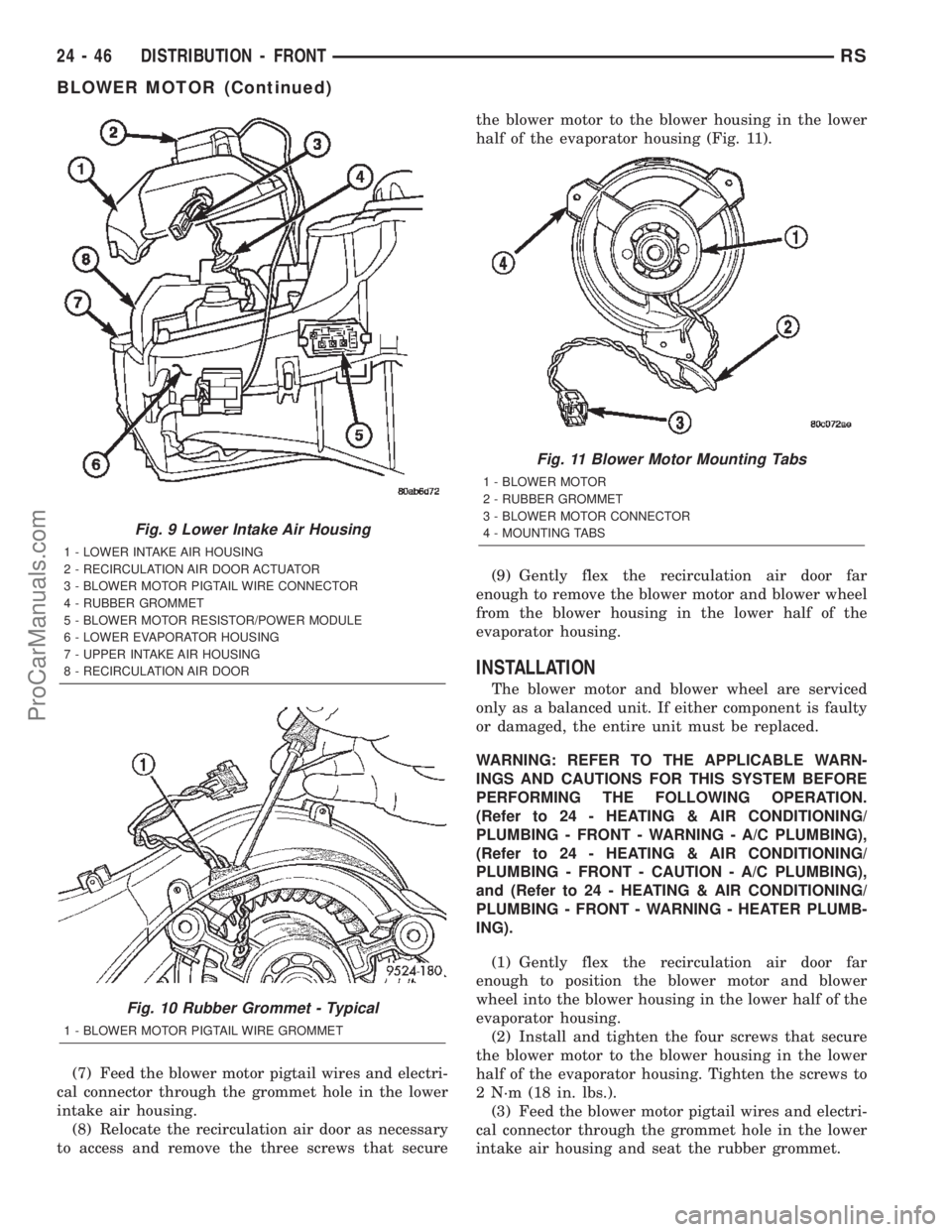
(7) Feed the blower motor pigtail wires and electri-
cal connector through the grommet hole in the lower
intake air housing.
(8) Relocate the recirculation air door as necessary
to access and remove the three screws that securethe blower motor to the blower housing in the lower
half of the evaporator housing (Fig. 11).
(9) Gently flex the recirculation air door far
enough to remove the blower motor and blower wheel
from the blower housing in the lower half of the
evaporator housing.
INSTALLATION
The blower motor and blower wheel are serviced
only as a balanced unit. If either component is faulty
or damaged, the entire unit must be replaced.
WARNING: REFER TO THE APPLICABLE WARN-
INGS AND CAUTIONS FOR THIS SYSTEM BEFORE
PERFORMING THE FOLLOWING OPERATION.
(Refer to 24 - HEATING & AIR CONDITIONING/
PLUMBING - FRONT - WARNING - A/C PLUMBING),
(Refer to 24 - HEATING & AIR CONDITIONING/
PLUMBING - FRONT - CAUTION - A/C PLUMBING),
and (Refer to 24 - HEATING & AIR CONDITIONING/
PLUMBING - FRONT - WARNING - HEATER PLUMB-
ING).
(1) Gently flex the recirculation air door far
enough to position the blower motor and blower
wheel into the blower housing in the lower half of the
evaporator housing.
(2) Install and tighten the four screws that secure
the blower motor to the blower housing in the lower
half of the evaporator housing. Tighten the screws to
2 N´m (18 in. lbs.).
(3) Feed the blower motor pigtail wires and electri-
cal connector through the grommet hole in the lower
intake air housing and seat the rubber grommet.
Fig. 9 Lower Intake Air Housing
1 - LOWER INTAKE AIR HOUSING
2 - RECIRCULATION AIR DOOR ACTUATOR
3 - BLOWER MOTOR PIGTAIL WIRE CONNECTOR
4 - RUBBER GROMMET
5 - BLOWER MOTOR RESISTOR/POWER MODULE
6 - LOWER EVAPORATOR HOUSING
7 - UPPER INTAKE AIR HOUSING
8 - RECIRCULATION AIR DOOR
Fig. 10 Rubber Grommet - Typical
1 - BLOWER MOTOR PIGTAIL WIRE GROMMET
Fig. 11 Blower Motor Mounting Tabs
1 - BLOWER MOTOR
2 - RUBBER GROMMET
3 - BLOWER MOTOR CONNECTOR
4 - MOUNTING TABS
24 - 46 DISTRIBUTION - FRONTRS
BLOWER MOTOR (Continued)
ProCarManuals.com