2002 CHRYSLER TOWN AND COUNTRY Intake manifold gasket 3.3
[x] Cancel search: Intake manifold gasket 3.3Page 274 of 2399
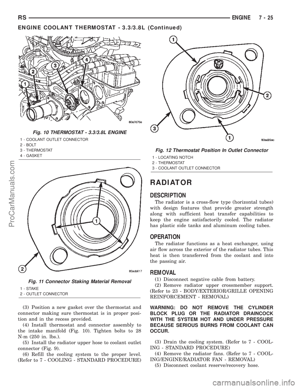
(3) Position a new gasket over the thermostat and
connector making sure thermostat is in proper posi-
tion and in the recess provided.
(4) Install thermostat and connector assembly to
the intake manifold (Fig. 10). Tighten bolts to 28
N´m (250 in. lbs.).
(5) Install the radiator upper hose to coolant outlet
connector (Fig. 9).
(6) Refill the cooling system to the proper level.
(Refer to 7 - COOLING - STANDARD PROCEDURE)
RADIATOR
DESCRIPTION
The radiator is a cross-flow type (horizontal tubes)
with design features that provide greater strength
along with sufficient heat transfer capabilities to
keep the engine satisfactorily cooled. The radiator
has plastic side tanks and aluminum cooling tubes.
OPERATION
The radiator functions as a heat exchanger, using
air flow across the exterior of the radiator tubes. This
heat is then transferred from the coolant and into
the passing air.
REMOVAL
(1) Disconnect negative cable from battery.
(2) Remove radiator upper crossmember support.
(Refer to 23 - BODY/EXTERIOR/GRILLE OPENING
REINFORCEMENT - REMOVAL)
WARNING: DO NOT REMOVE THE CYLINDER
BLOCK PLUG OR THE RADIATOR DRAINCOCK
WITH THE SYSTEM HOT AND UNDER PRESSURE
BECAUSE SERIOUS BURNS FROM COOLANT CAN
OCCUR.
(3) Drain the cooling system. (Refer to 7 - COOL-
ING - STANDARD PROCEDURE)
(4) Remove the radiator fans. (Refer to 7 - COOL-
ING/ENGINE/RADIATOR FAN - REMOVAL)
(5) Disconnect coolant reserve/recovery hose.
Fig. 10 THERMOSTAT - 3.3/3.8L ENGINE
1 - COOLANT OUTLET CONNECTOR
2 - BOLT
3 - THERMOSTAT
4 - GASKET
Fig. 11 Connector Staking Material Removal
1-STAKE
2 - OUTLET CONNECTOR
Fig. 12 Thermostat Position In Outlet Connector
1 - LOCATING NOTCH
2 - THERMOSTAT
3 - COOLANT OUTLET CONNECTOR
RSENGINE7-25
ENGINE COOLANT THERMOSTAT - 3.3/3.8L (Continued)
ProCarManuals.com
Page 1278 of 2399
DIAGNOSIS AND TESTING
DIAGNOSIS AND TESTING - ENGINE
DIAGNOSIS - INTRODUCTION
Engine diagnosis is helpful in determining the
causes of malfunctions not detected and remedied by
routine maintenance.
These malfunctions may be classified as either
mechanical (e.g., a strange noise), or performance
(e.g., engine idles rough and stalls).
Refer to the Engine Mechanical and the Engine
Performance diagnostic charts, for possible causes
and corrections of malfunctions (Refer to 9 - ENGINE
- DIAGNOSIS AND TESTING - MECHANICAL)
(Refer to 9 - ENGINE - DIAGNOSIS AND TESTING
- PERFORMANCE).
For fuel system diagnosis, (Refer to 14 - FUEL
SYSTEM/FUEL DELIVERY - DIAGNOSIS AND
TESTING).
Additional tests and diagnostic procedures may be
necessary for specific engine malfunctions that can-
not be isolated with the Service Diagnosis charts.
Information concerning additional tests and diagno-
sis is provided within the following:
²Cylinder Compression Pressure Test
²Cylinder Combustion Pressure Leakage Test
²Engine Cylinder Head Gasket Failure Diagnosis
²Intake Manifold Leakage Diagnosis
²Hydraulic Lash Adjuster Noise Diagnosis
²Engine Oil Leak Inspection
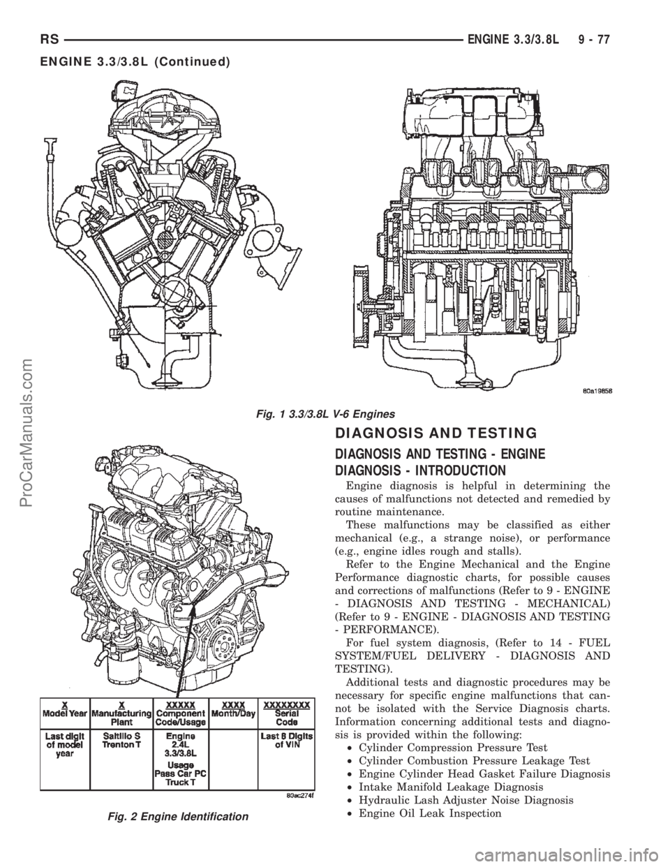
Fig. 1 3.3/3.8L V-6 Engines
Fig. 2 Engine Identification
RSENGINE 3.3/3.8L9-77
ENGINE 3.3/3.8L (Continued)
ProCarManuals.com
Page 1279 of 2399
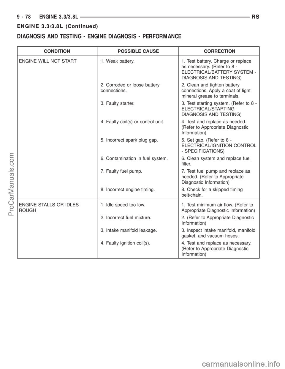
DIAGNOSIS AND TESTING - ENGINE DIAGNOSIS - PERFORMANCE
CONDITION POSSIBLE CAUSE CORRECTION
ENGINE WILL NOT START 1. Weak battery. 1. Test battery. Charge or replace
as necessary. (Refer to 8 -
ELECTRICAL/BATTERY SYSTEM -
DIAGNOSIS AND TESTING)
2. Corroded or loose battery
connections.2. Clean and tighten battery
connections. Apply a coat of light
mineral grease to terminals.
3. Faulty starter. 3. Test starting system. (Refer to 8 -
ELECTRICAL/STARTING -
DIAGNOSIS AND TESTING)
4. Faulty coil(s) or control unit. 4. Test and replace as needed.
(Refer to Appropriate Diagnostic
Information)
5. Incorrect spark plug gap. 5. Set gap. (Refer to 8 -
ELECTRICAL/IGNITION CONTROL
- SPECIFICATIONS)
6. Contamination in fuel system. 6. Clean system and replace fuel
filter.
7. Faulty fuel pump. 7. Test fuel pump and replace as
needed. (Refer to Appropriate
Diagnostic Information)
8. Incorrect engine timing. 8. Check for a skipped timing
belt/chain.
ENGINE STALLS OR IDLES
ROUGH1. Idle speed too low. 1. Test minimum air flow. (Refer to
Appropriate Diagnostic Information)
2. Incorrect fuel mixture. 2. (Refer to Appropriate Diagnostic
Information)
3. Intake manifold leakage. 3. Inspect intake manifold, manifold
gasket, and vacuum hoses.
4. Faulty ignition coil(s). 4. Test and replace as necessary.
(Refer to Appropriate Diagnostic
Information)
9 - 78 ENGINE 3.3/3.8LRS
ENGINE 3.3/3.8L (Continued)
ProCarManuals.com
Page 1297 of 2399
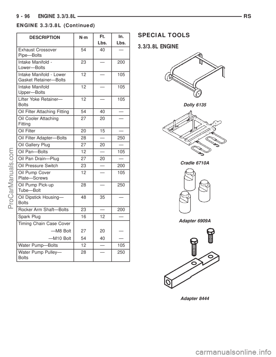
DESCRIPTION N´mFt.
Lbs.In.
Lbs.
Exhaust Crossover
PipeÐBolts54 40 Ð
Intake Manifold -
LowerÐBolts23 Ð 200
Intake Manifold - Lower
Gasket RetainerÐBolts12 Ð 105
Intake Manifold
UpperÐBolts12 Ð 105
Lifter Yoke RetainerÐ
Bolts12 Ð 105
Oil Filter Attaching Fitting 54 40 Ð
Oil Cooler Attaching
Fitting27 20 Ð
Oil Filter 20 15 Ð
Oil Filter AdapterÐBolts 28 Ð 250
Oil Gallery Plug 27 20 Ð
Oil PanÐBolts 12 Ð 105
Oil Pan DrainÐPlug 27 20 Ð
Oil Pressure Switch 23 Ð 200
Oil Pump Cover
PlateÐScrews12 Ð 105
Oil Pump Pick-up
TubeÐBolt28 Ð 250
Oil Dipstick HousingÐ
Bolts48 35 Ð
Rocker Arm ShaftÐBolts 23 Ð 200
Spark Plug 16 12 Ð
Timing Chain Case Cover
ÐM8 Bolt 27 20 Ð
ÐM10 Bolt 54 40 Ð
Water PumpÐBolts 12 Ð 105
Water Pump PulleyÐ
Bolts28 Ð 250SPECIAL TOOLS
3.3/3.8L ENGINE
Dolly 6135
Cradle 6710A
Adapter 6909A
Adapter 8444
9 - 96 ENGINE 3.3/3.8LRS
ENGINE 3.3/3.8L (Continued)
ProCarManuals.com
Page 1301 of 2399
INSTALLATION
(1) Install air box into vehicle and onto the locat-
ing pin.
(2) Install bolt to hold air box to the upper radia-
tor cross member.
(3) Install the inlet hose to the throttle body.
(4) Connect the inlet air temperature sensor (Fig.
16).
(5) Connect the negative battery cable.
CYLINDER HEAD
DESCRIPTION
The aluminum cylinder heads (Fig. 17) are
designed to create high flow combustion chambers to
improve performance, while minimizing the change
to the burn rate in the chamber. The cylinder head
incorporates the combustion chamber. Two valves
per-cylinder are used with inserted valve seats and
guides. A multi-layer steel (MLS) type gasket is used
between the cylinder head and engine block.
OPERATION
The cylinder head closes the combustion chamber,
allowing the pistons to compress the fuel/air mixture
for ignition. The valves are actuated by the lobe pro-
files on the camshaft to open and close at specified
duration to either allow clean air in the combustion
chamber or the exhaust gases out; depending on the
stroke of the engine.
DIAGNOSIS AND TESTINGÐCYLINDER HEAD
GASKET
A cylinder head gasket leak can be located between
adjacent cylinders or between a cylinder and the
adjacent water jacket.
Possible indications of the cylinder head gasket
leaking between adjacent cylinders are:
²Loss of engine power
²Engine misfiring
²Poor fuel economy
Possible indications of the cylinder head gasket
leaking between a cylinder and an adjacent water
jacket are:
²Engine overheating
²Loss of coolant
²Excessive steam (white smoke) emitting from
exhaust
²Coolant foaming
CYLINDER-TO-CYLINDER LEAKAGE TEST
To determine if an engine cylinder head gasket is
leaking between adjacent cylinders, follow the proce-
dures in Cylinder Compression Pressure Test (Refer
to 9 - ENGINE - DIAGNOSIS AND TESTING). An
engine cylinder head gasket leaking between adja-
cent cylinders will result in approximately a 50±70%
reduction in compression pressure.
CYLINDER-TO-WATER JACKET LEAKAGE TEST
WARNING: USE EXTREME CAUTION WHEN THE
ENGINE IS OPERATING WITH COOLANT PRES-
SURE CAP REMOVED.
VISUAL TEST METHOD
With the engine cool, remove the coolant pressure
cap. Start the engine and allow it to warm up until
thermostat opens.
If a large combustion/compression pressure leak
exists, bubbles will be visible in the coolant.
COOLING SYSTEM TESTER METHOD
WARNING: WITH COOLING SYSTEM TESTER IN
PLACE, PRESSURE WILL BUILD UP FAST. EXCES-
SIVE PRESSURE BUILT UP, BY CONTINUOUS
ENGINE OPERATION, MUST BE RELEASED TO A
SAFE PRESSURE POINT. NEVER PERMIT PRES-
SURE TO EXCEED 138 kPa (20 psi).
Install Cooling System Tester 7700 or equivalent to
pressure cap neck. Start the engine and observe the
tester's pressure gauge. If gauge pulsates with every
power stroke of a cylinder a combustion pressure
leak is evident.
CHEMICAL TEST METHOD
Combustion leaks into the cooling system can also
be checked by using Bloc-Chek Kit C-3685-A or
equivalent. Perform test following the procedures
supplied with the tool kit.
REMOVAL - CYLINDER HEAD
(1) Drain the cooling system. (Refer to 7 - COOL-
ING - STANDARD PROCEDURE)
(2) Disconnect negative cable from battery.
(3) Remove upper and lower intake manifolds.
(Refer to 9 - ENGINE/MANIFOLDS/INTAKE MANI-
FOLD - REMOVAL)
WARNING: INTAKE MANIFOLD GASKET IS MADE
OF VERY THIN METAL AND MAY CAUSE PER-
SONAL INJURY, HANDLE WITH CARE.
9 - 100 ENGINE 3.3/3.8LRS
AIR CLEANER HOUSING (Continued)
ProCarManuals.com
Page 1302 of 2399
(4) Remove the cylinder head covers. (Refer to 9 -
ENGINE/CYLINDER HEAD/CYLINDER HEAD
COVER(S) - REMOVAL)
(5) Remove the spark plugs from cylinder head.
(6) Remove the dipstick and tube (Fig. 18).
(7) Remove exhaust manifold(s). (Refer to 9 -
ENGINE/MANIFOLDS/EXHAUST MANIFOLD -
REMOVAL)
(8) Remove rocker arm and shaft assemblies.(Refer
to 9 - ENGINE/CYLINDER HEAD/ROCKER ARMS -
REMOVAL) Remove push rods andmark positions
to ensure installation in original locations.
(9) Remove the eight head bolts from each cylinder
head and remove cylinder heads (Fig. 22).
CLEANING
To ensure engine gasket sealing, proper surface
preparation must be performed, especially with the
use of aluminum engine components and multi-layer
steel cylinder head gaskets.NOTE: Multi-Layer Steel (MLS) head gaskets require
a scratch free sealing surface.
Remove all gasket material from cylinder head and
block (Refer to 9 - ENGINE - STANDARD PROCE-
DURE). Be careful not to gouge or scratch the alumi-
num head sealing surface.
Clean all engine oil passages.
INSPECTION
(1) Before cleaning, check for leaks, damage and
cracks.
(2) Clean cylinder head and oil passages.
(3) Check cylinder head for flatness (Fig. 19).
(4) Cylinder head must be flat within:
²Standard dimension = less than 0.05 mm (0.002
inch.)
²Service Limit = 0.2 mm (0.008 inch.)
²Grinding Limit = Maximum of 0.2 mm (0.008
inch.) is permitted.
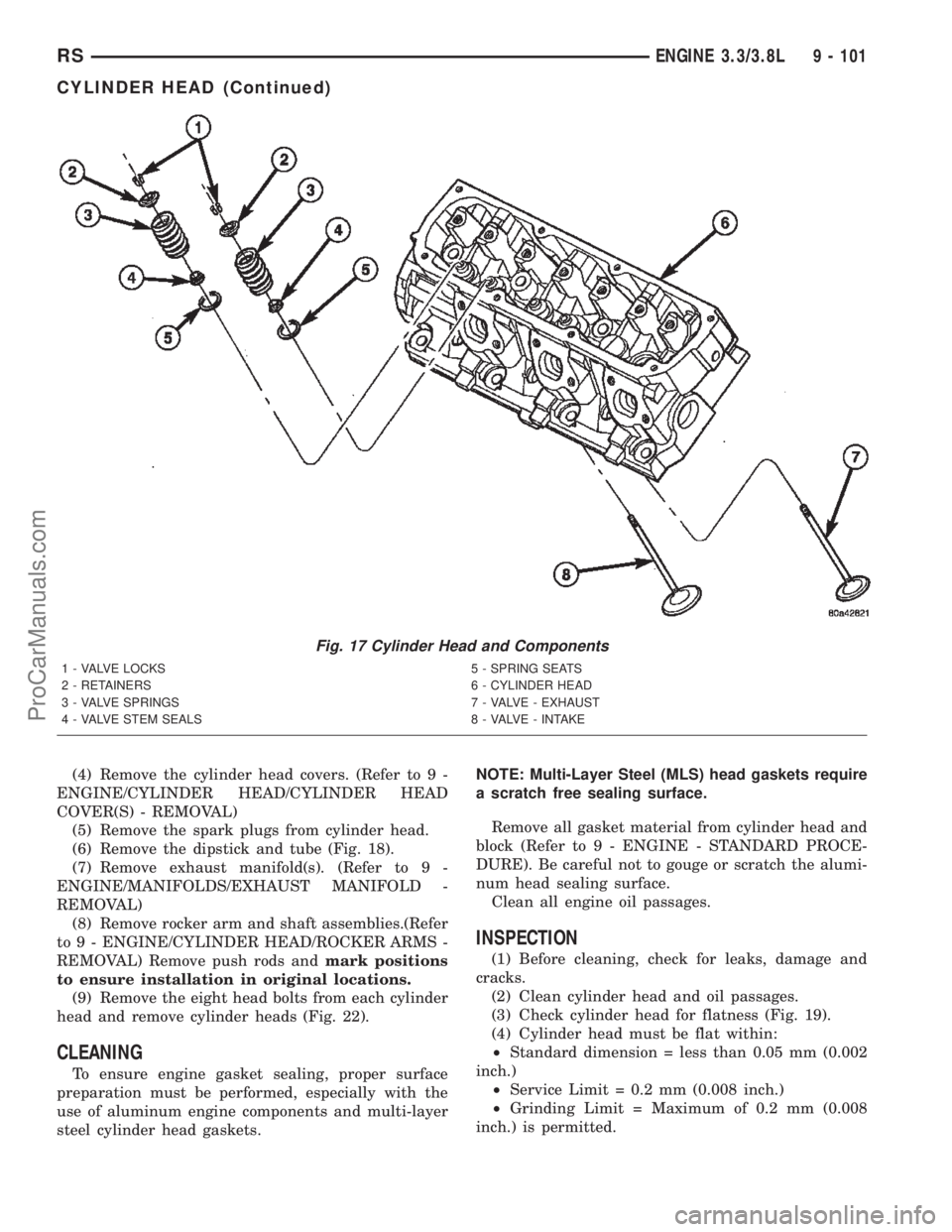
Fig. 17 Cylinder Head and Components
1 - VALVE LOCKS 5 - SPRING SEATS
2 - RETAINERS 6 - CYLINDER HEAD
3 - VALVE SPRINGS 7 - VALVE - EXHAUST
4 - VALVE STEM SEALS 8 - VALVE - INTAKE
RSENGINE 3.3/3.8L9 - 101
CYLINDER HEAD (Continued)
ProCarManuals.com
Page 1304 of 2399
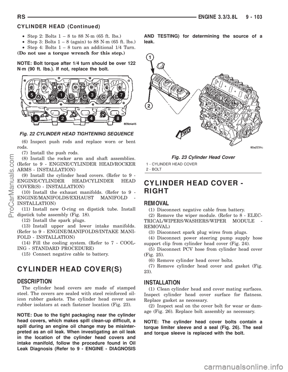
²Step 2: Bolts1±8to88N´m(65ft.lbs.)
²Step 3: Bolts1±8(again) to 88 N´m (65 ft. lbs.)
²Step 4: Bolts1±8turn an additional 1/4 Turn.
(Do not use a torque wrench for this step.)
NOTE: Bolt torque after 1/4 turn should be over 122
N´m (90 ft. lbs.). If not, replace the bolt.
(6) Inspect push rods and replace worn or bent
rods.
(7) Install the push rods.
(8) Install the rocker arm and shaft assemblies.
(Refer to 9 - ENGINE/CYLINDER HEAD/ROCKER
ARMS - INSTALLATION)
(9) Install the cylinder head covers. (Refer to 9 -
ENGINE/CYLINDER HEAD/CYLINDER HEAD
COVER(S) - INSTALLATION)
(10) Install the exhaust manifolds. (Refer to 9 -
ENGINE/MANIFOLDS/EXHAUST MANIFOLD -
INSTALLATION)
(11) Install new O-ring on dipstick tube. Install
dipstick tube assembly (Fig. 18).
(12) Install the spark plugs.
(13) Install upper and lower intake manifolds.
(Refer to 9 - ENGINE/MANIFOLDS/INTAKE MANI-
FOLD - INSTALLATION)
(14) Fill the cooling system. (Refer to 7 - COOL-
ING - STANDARD PROCEDURE)
(15) Connect negative cable to battery.
CYLINDER HEAD COVER(S)
DESCRIPTION
The cylinder head covers are made of stamped
steel. The covers are sealed with steel reinforced sil-
icon rubber gaskets. The cylinder head cover uses
rubber isolators at each fastener location (Fig. 23).
NOTE: Due to the tight packaging near the cylinder
head covers, which makes spill clean-up difficult, a
spill during an engine oil change may be misinter-
preted as an oil leak. When investigating an oil leak
in the location of the cylinder head covers and
intake manifold, follow the procedure found in Oil
Leak Diagnosis (Refer to 9 - ENGINE - DIAGNOSISAND TESTING) for determining the source of a
leak.
CYLINDER HEAD COVER -
RIGHT
REMOVAL
(1) Disconnect negative cable from battery.
(2) Remove the wiper module. (Refer to 8 - ELEC-
TRICAL/WIPERS/WASHERS/WIPER MODULE -
REMOVAL)
(3) Disconnect spark plug wires from plugs.
(4) Disconnect power steering pump supply hose
support clip from cylinder head cover (Fig. 24).
(5) Disconnect PCV hose from cylinder head cover
(Fig. 25).
(6) Remove cylinder head cover bolts.
(7) Remove cylinder head cover and gasket (Fig.
23).
INSTALLATION
(1) Clean cylinder head and cover mating surfaces.
Inspect cylinder head cover surface for flatness.
Replace gasket as necessary.
(2) Inspect seal on the cover bolt for wear or dam-
age (Fig. 26). Replace bolt assembly as necessary.
NOTE: The cylinder head cover bolts contain a
torque limiter sleeve and a seal (Fig. 26). The seal
and torque sleeve is replaced with the bolt.
Fig. 22 CYLINDER HEAD TIGHTENING SEQUENCE
Fig. 23 Cylinder Head Cover
1 - CYLINDER HEAD COVER
2 - BOLT
RSENGINE 3.3/3.8L9 - 103
CYLINDER HEAD (Continued)
ProCarManuals.com
Page 1349 of 2399
(7) Disconnect the manifold absolute pressure
(MAP) sensor electrical connector.
(8) Disconnect the vapor purge vacuum hose from
throttle body.
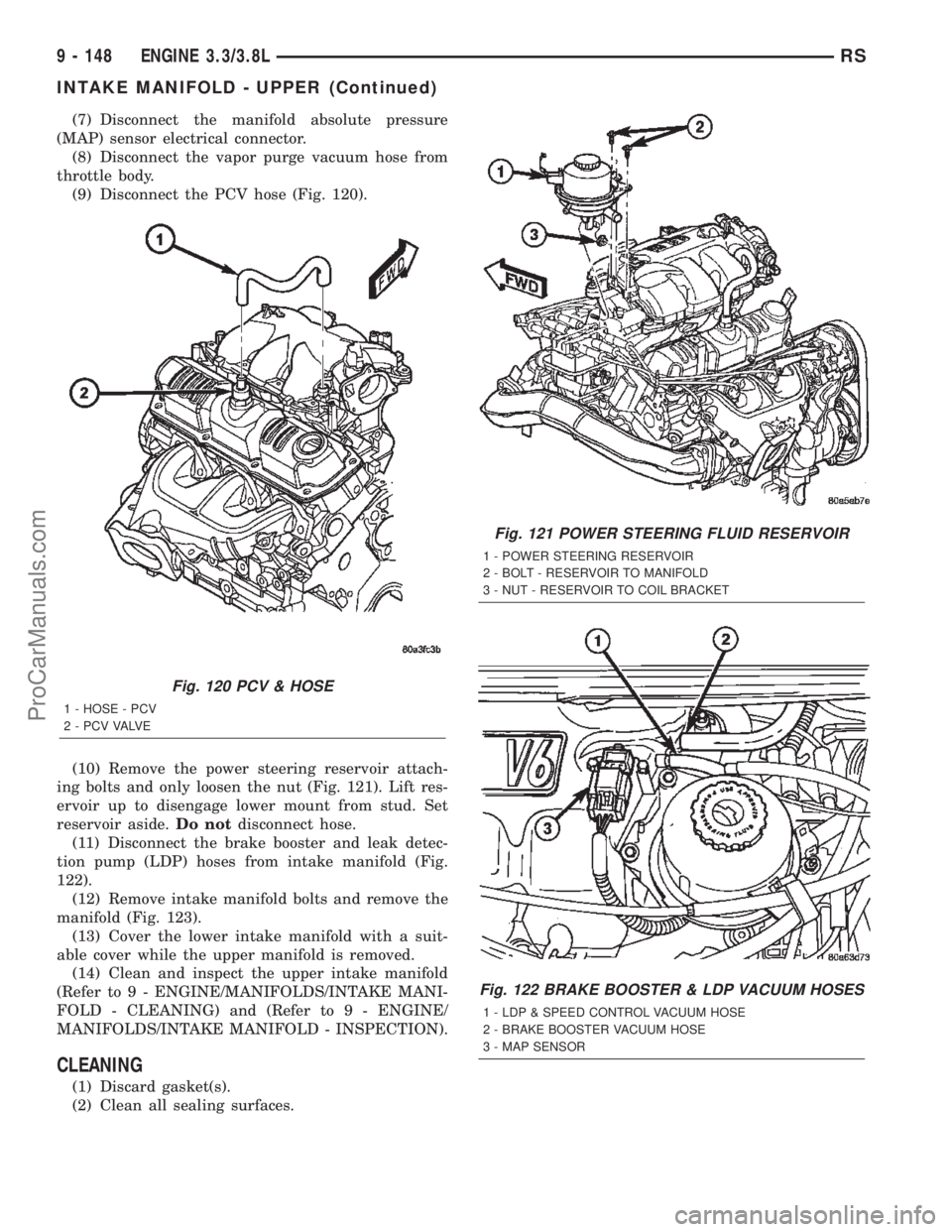
(9) Disconnect the PCV hose (Fig. 120).
(10) Remove the power steering reservoir attach-
ing bolts and only loosen the nut (Fig. 121). Lift res-
ervoir up to disengage lower mount from stud. Set
reservoir aside.Do notdisconnect hose.
(11) Disconnect the brake booster and leak detec-
tion pump (LDP) hoses from intake manifold (Fig.
122).
(12) Remove intake manifold bolts and remove the
manifold (Fig. 123).
(13) Cover the lower intake manifold with a suit-
able cover while the upper manifold is removed.
(14) Clean and inspect the upper intake manifold
(Refer to 9 - ENGINE/MANIFOLDS/INTAKE MANI-
FOLD - CLEANING) and (Refer to 9 - ENGINE/
MANIFOLDS/INTAKE MANIFOLD - INSPECTION).
CLEANING
(1) Discard gasket(s).
(2) Clean all sealing surfaces.
Fig. 120 PCV & HOSE
1 - HOSE - PCV
2 - P C V VA LV E
Fig. 121 POWER STEERING FLUID RESERVOIR
1 - POWER STEERING RESERVOIR
2 - BOLT - RESERVOIR TO MANIFOLD
3 - NUT - RESERVOIR TO COIL BRACKET
Fig. 122 BRAKE BOOSTER & LDP VACUUM HOSES
1 - LDP & SPEED CONTROL VACUUM HOSE
2 - BRAKE BOOSTER VACUUM HOSE
3 - MAP SENSOR
9 - 148 ENGINE 3.3/3.8LRS
INTAKE MANIFOLD - UPPER (Continued)
ProCarManuals.com