2002 CHRYSLER TOWN AND COUNTRY motor mount
[x] Cancel search: motor mountPage 2314 of 2399
lower half of the door. Tighten the screws to 2 N´m
(18 in. lbs.).
(6) Position the upper intake air housing onto the
top of the evaporator housing over the recirculation
air door and the blower wheel housing. Be certain
that the upper pivot of the recirculation air door is
captured in the pivot receptacle of the upper intake
air housing.
(7) Install and tighten the three screws that secure
the upper intake air housing to the top of the out-
board end of the evaporator housing. Be certain not
to miss the screw located just inside the inboard side
of the fresh air intake opening. Tighten the screws to
2 N´m (18 in. lbs.).
(8) Install and tighten the two screws that secure
the upper intake air housing to the lower intake air
housing. Tighten the screws to 2 N´m (18 in. lbs.).
(9) Engage the two hook formations on the bottom
of the distribution housing in the two receptacles on
the evaporator housing.
(10) Roll the top of the distribution housing up
into position against the evaporator housing.
(11) Install and tighten the three screws from the
dash panel side of the unit that secure the top of the
distribution housing to the inboard end of the evapo-
rator housing. Tighten the screws to 2 N´m (18 in.
lbs.).
(12) Engage the HVAC wire harness in the routing
clips molded into the outside of the HVAC housing
components.
(13) Reconnect the HVAC wire harness connector
for the blower motor with the motor connector recep-
tacle on the bottom of the outboard end of the evap-
orator housing.
(14) Reinstall the expansion valve onto the evapo-
rator inlet and outlet tube fittings. (Refer to 24 -
HEATING & AIR CONDITIONING/PLUMBING -
FRONT/EXPANSION VALVE - INSTALLATION).
(15) Install a new foam seal onto the HVAC hous-
ing seal flange around the fresh air inlet opening and
the expansion valve/evaporator tube opening on the
dash panel side of the unit.
(16) Reinstall the heater core tubes into the heater
core. (Refer to 24 - HEATING & AIR CONDITION-
ING/PLUMBING - FRONT/HEATER CORE -
INSTALLATION - HEATER CORE TUBES).
(17) Reinstall the HVAC unit housing into the
vehicle. (Refer to 24 - HEATING & AIR CONDI-
TIONING/DISTRIBUTION - FRONT/HVAC HOUS-
ING - INSTALLATION).
(18) Run the HVAC Control Actuator Calibration
procedure(Refer to 24 - HEATING & AIR CONDI-
TIONING - DIAGNOSIS AND TESTING)(Refer to 24
- HEATING & AIR CONDITIONING - DIAGNOSIS
AND TESTING).EXPANSION VALVE
DESCRIPTION
The front ªHº valve-type thermal expansion valve
(TXV) is located at the dash panel between the liquid
and suction lines, and the evaporator coil. The
assembly consists of an H-valve body and a thermal
sensor. High-pressure, low temperature liquid refrig-
erant from the liquid line passes through the expan-
sion valve orifice, converting it into a low-pressure,
low-temperature mixture of liquid and gas before it
enters the evaporator coil. The expansion valve is a
factory calibrated unit and cannot be adjusted or
repaired. If faulty or damaged, the expansion valve
must be replaced.
OPERATION
A mechanical sensor in the expansion valve control
head monitors the temperature and pressure of the
refrigerant leaving the evaporator coil through the
suction line, and adjusts the orifice size at the liquid
line to let the proper amount of refrigerant into the
evaporator coil to meet the vehicle cooling require-
ments. Controlling the refrigerant flow through the
evaporator ensures that none of the refrigerant leav-
ing the evaporator is still in a liquid state, which
could damage the compressor. The thermo sensor
measures refrigerant suction gas temperature which
is monitored by the a/c control assembly.
DIAGNOSIS AND TESTING - EXPANSION VALVE
WARNING: REFER TO THE APPLICABLE WARN-
INGS AND CAUTIONS FOR THIS SYSTEM BEFORE
PERFORMING THE FOLLOWING OPERATION.
(Refer to 24 - HEATING & AIR CONDITIONING/
PLUMBING - FRONT - WARNING - A/C PLUMBING)
and (Refer to 24 - HEATING & AIR CONDITIONING/
PLUMBING - FRONT - CAUTION - A/C PLUMBING).
NOTE: The expansion valve should only be tested
following testing of the compressor.
NOTE: Liquid CO is required to test the expansion
valve. This material is available from most welding
supply facilities. Liquid CO is also available from
companies which service and sell fire extinguish-
ers.
When testing the expansion valve, the work area
and the vehicle temperature must be 21É to 27É C
(70É to 85É F). To test the expansion valve:
(1) Connect a charging station or manifold gauge
set to the refrigerant system service ports. Verify the
refrigerant charge level.
RSPLUMBING - FRONT24-71
EVAPORATOR (Continued)
ProCarManuals.com
Page 2335 of 2399
²Single or Dual Zone (Front Unit Only - with
2.5L Turbo Diesel)0.91 kilograms (2.00 pounds or
32 ounces)
²Single or Dual Zone (Front Unit Only)- 0.96
kilograms (2.13 pounds or 34 ounces)
²Three Zone (Front and Rear Units)- 1.31
kilograms (2.88 pounds or 46 ounces)
CHARGING PROCEDURE
(1) Evacuate the refrigerant system. (Refer to 24 -
HEATING & AIR CONDITIONING/PLUMBING -
FRONT/REFRIGERANT - STANDARD PROCE-
DURE - REFRIGERANT SYSTEM EVACUATE).
(2) A manifold gauge set and a R-134a refrigerant
recovery/recycling/charging station that meets SAE
Standard J2210 should still be connected to the
refrigerant system.
(3) Measure the proper amount of refrigerant and
heat it to 52É C (125É F) with the charging station.
See the operating instructions supplied by the equip-
ment manufacturer for proper use of this equipment.
(4) Open both the suction and discharge valves,
then open the charge valve to allow the heated
refrigerant to flow into the system.
(5) When the transfer of refrigerant has stopped,
close both the suction and discharge valves.
(6) If all of the refrigerant charge did not transfer
from the dispensing device, open all of the windows
in the vehicle and set the heater-air conditioner con-
trols so that the compressor is engaged and the
blower motor is operating at its lowest speed setting.
Run the engine at a steady high idle (about 1400
rpm). If the compressor will not engage, test the com-
pressor clutch control circuit and repair as required.
(7) Open the suction valve to allow the remaining
refrigerant to transfer to the refrigerant system.
WARNING: TAKE CARE NOT TO OPEN THE DIS-
CHARGE (HIGH PRESSURE) VALVE AT THIS TIME.
(8) Close the suction valve and test the system
performance. (Refer to 24 - HEATING & AIR CON-
DITIONING - STANDARD PROCEDURE - A/C PER-
FORMANCE TEST).
(9) Disconnect the charging station and manifold
gauge set from the refrigerant system service ports.
(10) Reinstall the caps onto the refrigerant system
service ports.
(11) Run the HVAC Control Cooldown test to ver-
ify proper operation(Refer to 24 - HEATING & AIR
CONDITIONING - DIAGNOSIS AND TESTING).
STANDARD PROCEDURE - REFRIGERANT
SYSTEM EVACUATE
WARNING: REFER TO THE APPLICABLE WARN-
INGS AND CAUTIONS FOR THIS SYSTEM BEFOREPERFORMING THE FOLLOWING OPERATION.
(Refer to 24 - HEATING & AIR CONDITIONING/
PLUMBING - FRONT - WARNING - A/C PLUMBING)
and (Refer to 24 - HEATING & AIR CONDITIONING/
PLUMBING - FRONT - CAUTION - A/C PLUMBING).
If the refrigerant system has been open to the
atmosphere, it must be evacuated before the system
can be charged. If moisture and air enters the system
and becomes mixed with the refrigerant, the com-
pressor head pressure will rise above acceptable
operating levels. This will reduce the performance of
the air conditioner and damage the compressor.
Evacuating the refrigerant system will remove the
air and boil the moisture out of the system at near
room temperature. A R-134a refrigerant recovery/re-
cycling/charging station that meets SAE Standard
J2210 must be used to evacuate the refrigerant sys-
tem. See the operating instructions supplied by the
equipment manufacturer for proper care and use of
this equipment. To evacuate the refrigerant system,
use the following procedure:
NOTE: When connecting the service equipment
couplings to the refrigerant system service ports,
be certain that the valve of each coupling is fully
closed. This will reduce the amount of effort
required to make the connection.
(1) Remove the caps from the refrigerant system
service ports and attach a manifold gauge set and a
R-134a refrigerant recovery/recycling/charging sta-
tion that meets SAE Standard J2210 to the refriger-
ant system.
(2) Open both the suction and discharge valves
and start the charging station vacuum pump.
(3) When the suction gauge has read 88 kPa (26
in. Hg.) vacuum or greater for 45 minutes, close both
the suction and discharge valves and turn off the
vacuum pump. If the refrigerant system fails to
reach the specified vacuum, the system has a leak
that must be corrected. (Refer to 24 - HEATING &
AIR CONDITIONING/PLUMBING - FRONT/RE-
FRIGERANT - STANDARD PROCEDURE -
REFRIGERANT SYSTEM LEAKS).
(4) If the refrigerant system maintains the speci-
fied vacuum for thirty minutes, restart the vacuum
pump, open both the suction and discharge valves,
and evacuate the system for an additional ten min-
utes.
(5) Close both the suction and discharge valves,
and turn off the charging station vacuum pump.
(6) The refrigerant system is now ready to be
charged with R-134a refrigerant. (Refer to 24 -
HEATING & AIR CONDITIONING/PLUMBING -
FRONT/REFRIGERANT - STANDARD PROCE-
DURE - REFRIGERANT SYSTEM CHARGE).
24 - 92 PLUMBING - FRONTRS
REFRIGERANT (Continued)
ProCarManuals.com
Page 2361 of 2399
The following is a list of the monitored compo-
nents:
²Comprehensive Components
²Oxygen Sensor Monitor
²Oxygen Sensor Heater Monitor
²Catalyst Monitor
COMPREHENSIVE COMPONENTS
Along with the major monitors, OBD II requires
that the diagnostic system monitor any component
that could affect emissions levels. In many cases,
these components were being tested under OBD I.
The OBD I requirements focused mainly on testing
emissions-related components for electrical opens and
shorts.
However, OBD II also requires that inputs from
powertrain components to the PCM be tested for
rationality, and that outputs to powertrain compo-
nents from the PCM be tested forfunctionality.
Methods for monitoring the various Comprehensive
Component monitoring include:
(1) Circuit Continuity
²Open
²Shorted high
²Shorted to ground
(2) Rationality or Proper Functioning
²Inputs tested for rationality
²Outputs tested for functionality
NOTE: Comprehensive component monitors are
continuous. Therefore, enabling conditions do not
apply.
Input RationalityÐWhile input signals to the
PCM are constantly being monitored for electrical
opens and shorts, they are also tested for rationality.
This means that the input signal is compared against
other inputs and information to see if it makes sense
under the current conditions.
PCM sensor inputs that are checked for rationality
include:
²Manifold Absolute Pressure (MAP) Sensor
²Oxygen Sensor (O2S)
²Engine Coolant Temperature (ECT) Sensor
²Camshaft Position (CMP) Sensor
²Vehicle Speed Sensor
²Crankshaft Position (CKP) Sensor
²Intake/inlet Air Temperature (IAT) Sensor
²Throttle Position (TPS) Sensor
²Ambient/Battery Temperature Sensors
²Power Steering Switch
²Oxygen Sensor Heater
²Engine Controller
²Brake Switch
²Leak Detection Pump Switch (if equipped)
²P/N Switch
²Trans ControlsOutput FunctionalityÐPCM outputs are tested
for functionality in addition to testing for opens and
shorts. When the PCM provides a voltage to an out-
put component, it can verify that the command was
carried out by monitoring specific input signals for
expected changes. For example, when the PCM com-
mands the Idle Air Control (IAC) Motor to a specific
position under certain operating conditions, it expects
to see a specific (target) idle speed (RPM). If it does
not, it stores a DTC.
PCM outputs monitored for functionality include:
²Fuel Injectors
²Ignition Coils
²Torque Converter Clutch Solenoid
²Idle Air Control
²Purge Solenoid
²EGR Solenoid (if equipped)
²LDP Solenoid (if equipped)
²Radiator Fan Control
²Trans Controls
OXYGEN SENSOR (O2S) MONITOR
DESCRIPTIONÐEffective control of exhaust
emissions is achieved by an oxygen feedback system.
The most important element of the feedback system
is the O2S. The O2S is located in the exhaust path.
Once it reaches operating temperature 300É to 350ÉC
(572É to 662ÉF), the sensor generates a voltage that
is inversely proportional to the amount of oxygen in
the exhaust. When there is a large amount of oxygen
in the exhaust caused by a lean condition, the sensor
produces a low voltage, below 450 mV. When the oxy-
gen content is lower, caused by a rich condition, the
sensor produces a higher voltage, above 450mV.
The information obtained by the sensor is used to
calculate the fuel injector pulse width. The PCM is
programmed to maintain the optimum air/fuel ratio.
At this mixture ratio, the catalyst works best to
remove hydrocarbons (HC), carbon monoxide (CO)
and nitrous oxide (NOx) from the exhaust.
The O2S is also the main sensing element for the
EGR (if equipped), Catalyst and Fuel Monitors.
The O2S may fail in any or all of the following
manners:
²Slow response rate (Big Slope)
²Reduced output voltage (Half Cycle)
²Heater Performance
Slow Response Rate (Big Slope)ÐResponse rate
is the time required for the sensor to switch from
lean to rich signal output once it is exposed to a
richer than optimum A/F mixture or vice versa. As
the PCM adjusts the air/fuel ratio, the sensor must
be able to rapidly detect the change. As the sensor
ages, it could take longer to detect the changes in the
oxygen content of the exhaust gas. The rate of
change that an oxygen sensor experiences is called
25 - 2 EMISSIONS CONTROLRS
EMISSIONS CONTROL (Continued)
ProCarManuals.com
Page 2381 of 2399
the incoming air/fuel mixture. The diluted air/fuel
mixture reduces peak flame temperature during com-
bustion.
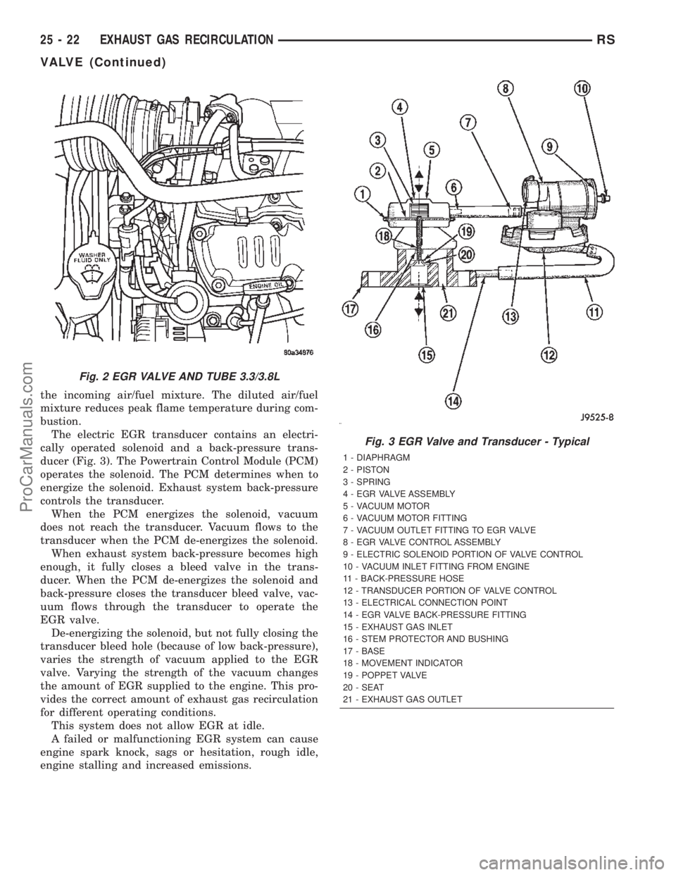
The electric EGR transducer contains an electri-
cally operated solenoid and a back-pressure trans-
ducer (Fig. 3). The Powertrain Control Module (PCM)
operates the solenoid. The PCM determines when to
energize the solenoid. Exhaust system back-pressure
controls the transducer.
When the PCM energizes the solenoid, vacuum
does not reach the transducer. Vacuum flows to the
transducer when the PCM de-energizes the solenoid.
When exhaust system back-pressure becomes high
enough, it fully closes a bleed valve in the trans-
ducer. When the PCM de-energizes the solenoid and
back-pressure closes the transducer bleed valve, vac-
uum flows through the transducer to operate the
EGR valve.
De-energizing the solenoid, but not fully closing the
transducer bleed hole (because of low back-pressure),
varies the strength of vacuum applied to the EGR
valve. Varying the strength of the vacuum changes
the amount of EGR supplied to the engine. This pro-
vides the correct amount of exhaust gas recirculation
for different operating conditions.
This system does not allow EGR at idle.
A failed or malfunctioning EGR system can cause
engine spark knock, sags or hesitation, rough idle,
engine stalling and increased emissions.
Fig. 2 EGR VALVE AND TUBE 3.3/3.8L
Fig. 3 EGR Valve and Transducer - Typical
1 - DIAPHRAGM
2 - PISTON
3 - SPRING
4 - EGR VALVE ASSEMBLY
5 - VACUUM MOTOR
6 - VACUUM MOTOR FITTING
7 - VACUUM OUTLET FITTING TO EGR VALVE
8 - EGR VALVE CONTROL ASSEMBLY
9 - ELECTRIC SOLENOID PORTION OF VALVE CONTROL
10 - VACUUM INLET FITTING FROM ENGINE
11 - BACK-PRESSURE HOSE
12 - TRANSDUCER PORTION OF VALVE CONTROL
13 - ELECTRICAL CONNECTION POINT
14 - EGR VALVE BACK-PRESSURE FITTING
15 - EXHAUST GAS INLET
16 - STEM PROTECTOR AND BUSHING
17 - BASE
18 - MOVEMENT INDICATOR
19 - POPPET VALVE
20 - SEAT
21 - EXHAUST GAS OUTLET
25 - 22 EXHAUST GAS RECIRCULATIONRS
VALVE (Continued)
ProCarManuals.com