2002 CHRYSLER TOWN AND COUNTRY motor mount
[x] Cancel search: motor mountPage 72 of 2399

THRUST ANGLE
Thrust angle is the averaged direction the rear
wheels are pointing in relation to the vehicle's center
line (Fig. 6). The presence of negative or positive
thrust angle causes the rear tires to track improperly
to the left or right of the front tires (dog tracking).
²Negative thrust angle means the rear tires are
tracking to the left of the front tires.
²Positive thrust angle means the rear tires are
tracking to the right of the front tires.
Improper tracking can cause undue tire wear, a
lead or pull and a crooked steering wheel. Excessive
thrust angle can usually be corrected by adjusting
the rear wheel toe so that each wheel has one-half of
the total toe measurement.
DIAGNOSIS AND TESTING - SUSPENSION AND STEERING
CONDITION POSSIBLE CAUSES CORRECTION
Front End Whine On Turns 1. Defective wheel bearing 1. Replace wheel bearing
2. Incorrect wheel alignment 2. Check and reset wheel alignment
3. Worn tires 3. Replace tires
Front End Growl Or
Grinding On Turns1. Defective wheel bearing 1. Replace wheel bearing
2. Engine mount grounding 2. Check for motor mount hitting frame rail
and reposition engine as required
3. Worn or broken C/V joint 3. Replace C/V joint
4. Loose wheel lug nuts 4. Verify wheel lug nut torque
5. Incorrect wheel alignment 5. Check and reset wheel alignment
6. Worn tires 6. Replace tires
7. Front strut pin in upper strut mount 7. Replace the front strut upper mount and
bearing
Front End Clunk Or Snap
On Turns1. Loose lug nuts 1. Verify wheel lug nut torque
2. Worn or broken C/V joint 2. Replace C/V joint
3. Worn or loose tie rod 3. Tighten or replace tie rod end
4. Worn or loose ball joint 4. Tighten or replace ball joint
5. Worn/loose control arm bushing 5. Replace control arm bushing
6. Loose stabilizer bar. 6. Tighten stabilizer bar to specified torque
Fig. 6 Thrust Angle
RSWHEEL ALIGNMENT2-49
WHEEL ALIGNMENT (Continued)
ProCarManuals.com
Page 171 of 2399

(5) Install wiring harness connector to brake fluid
level switch mounted in brake fluid reservoir (Fig.
57).
(6) Install battery, clamp and nut.
(7) Install battery shield.
(8) Connect positive battery terminal.
(9) Connect negative battery terminal.
(10) Fill master cylinder with clean, fresh Mopart
Brake Fluid or equivalent.
(11) Road test vehicle to ensure proper operation of
brakes.
INSTALLATION - RHD
CAUTION: Different types of master cylinders are
used on this vehicle depending on brake options. If
a new master cylinder is being installed, be sure it
is the correct master cylinder for the type of brake
system the vehicle is equipped with.
CAUTION: When replacing the master cylinder on a
vehicle, a NEW vacuum seal MUST be installed on
the master cylinder.
(1) Install a NEW vacuum seal on master cylinder
making sure seal fits squarely in groove of master
cylinder casting.
(2) Position master cylinder on studs of power
brake booster, aligning booster push rod with master
cylinder piston.
(3) Install the two master cylinder mounting nuts
(Fig. 59). Tighten both mounting nuts to a torque of
25 N´m (225 in. lbs.).
CAUTION: When tightening the primary and sec-
ondary brake tube nuts at master cylinder, be sure
brake tubes do not contact any other components
within the vehicle and that there is slack in the flex-
ible sections of the tubes. This is required due to
the movement between the ABS ICU and the master
cylinder while the vehicle is in motion.
(4) Connect primary and secondary brake tubes to
master cylinder primary and secondary ports (Fig.
59). Brake tubes must be held securely when tight-
ened to control orientation of flex section. Tighten
tube nuts to a torque of 17 N´m (145 in. lbs.).
(5) Install wiring harness connector to brake fluid
level switch mounted in brake fluid reservoir (Fig.
55).
(6) Install battery, clamp and nut.
(7) Install battery shield.
(8) Connect positive battery terminal.
(9) Connect negative battery terminal.
(10) Fill master cylinder with clean, fresh Mopart
Brake Fluid or equivalent.(11) Road test vehicle to ensure proper operation of
brakes.
PEDAL - ADJUSTABLE
DESCRIPTION
The Adjustable Pedals System (APS) is designed to
enable the fore and aft repositioning of the brake and
accelerator pedals. This results in improved ergonom-
ics in relation to the steering wheel for taller and
shorter drivers. Being able to adjust the pedal posi-
tions also allows the driver to set steering wheel tilt
and seat position to the most comfortable position.
The effort required for pedal application will not
change regardless of pedal position.
The adjustable pedal system allows the pedals to
adjust up to 3 inches (75 mm) at a rate of approxi-
mately 0.4 in./sec. (9 mm/sec.). An adjustment switch
is located on the left side of the steering column
lower shroud.
If the vehicle is equipped with Remote Keyless
Entry (RKE), an optional memory feature is avail-
able.
The serviceable components of the APS are:
²Adjustable pedal assembly (includes motor,
cables, pedals, gear box, sensor and module)
²Adjustable pedal module (Refer to 8 - ELECTRI-
CAL/ELECTRONIC CONTROL MODULES/
ADJUSTABLE PEDAL MODULE)
²Adjustable pedal switch
²Pedal position sensor
OPERATION
Change of pedal position is accomplished by means
of a motor driven screw. Operating the adjustable
pedal switch activates the pedal drive motor. The
pedal drive motor turns a screw that changes the
position of the accelerator pedal. The motor also
drives a cable connected to a gear box that changes
the brake pedal position the same distance as the
accelerator pedal. The pedals can be moved rearward
(closer to the driver) or forward (away from driver).
Each pedal is moved on its activating lever to a posi-
tion where the driver feels most comfortable. The
position and operation of the activating levers are not
changed.
Pedal adjustment is inhibited when the vehicle is
in reverse or when cruise control is engaged. The
Electronic Vehicle Information Center (EVIC) will
display a message when the Adjustable Pedal Module
(APM) is disabled. i.e.:9Adjustable Pedal Disabled -
Cruise Control Engaged9or9Adjustable Pedal Dis-
abled - Vehicle in Reverse9.
Foot pressure or debris can stall pedal adjustment.
In order to avoid damage to system components dur-
5 - 42 BRAKES - BASERS
MASTER CYLINDER (Continued)
ProCarManuals.com
Page 172 of 2399

ing pedal adjustment, the APM will monitor pedal
position sensor voltage. If the APM does not detect
expected voltage change within 3 seconds, it will cut
power to the adjustable pedal motor.
An optional memory feature is available. This
allows storing of one or two preferred pedal positions
in the APS. A preferred position can be stored and
recalled using the door-mounted switches. A stored
pedal position can be recalled (but not stored) using
the Remote Keyless Entry (RKE) if equipped with
the memory feature.
DIAGNOSIS AND TESTING - ADJUSTABLE
PEDAL SYSTEM
Refer to Appropriate Diagnostic Information.
REMOVAL
NOTE: Before proceeding, review all Steering Col-
umn and Airbag Warnings and Cautions. (Refer to
19 - STEERING/COLUMN - WARNING)(Refer to 8 -
ELECTRICAL/RESTRAINTS - WARNING)
(1) Remove battery ground cable terminal from
battery negative post and isolate.
(2) Under instrument panel, remove silencer panel
below lower steering column cover.
(3) Remove screws securing lower steering column
cover/knee blocker, then remove it (Fig. 62).(4) Disconnect parking brake release link at
release handle.
(5) Compress tabs on sides of data link diagnostic
connector and remove it from knee blocker reinforce-
ment plate.
(6) Remove screws securing knee blocker reinforce-
ment plate in place, then remove reinforcement plate
(Fig. 62).
(7) Remove screws securing instrument panel
lower left reinforcement in place, then remove rein-
forcement (Fig. 63).
(8) Remove brake lamp switch. Discard the origi-
nal switch; it must not be reused (Refer to 8 - ELEC-
TRICAL/LAMPS/LIGHTING - EXTERIOR/BRAKE
LAMP SWITCH - REMOVAL)
(9) Remove screws fastening upper and lower
steering column shrouds to steering column (Fig. 64).
(10) Remove the lower shroud with adjustable
pedal switch; disconnect switch wiring connector
along left side of column as shroud is removed (Fig.
65).
(11) Disconnect traction control off switch wiring
connector; Remove upper shroud with traction con-
trol off switch.
(12) Disconnect wiring harness connectors (as
equipped) from clockspring, multi-function switch,
halo lamp, SKIM module, ignition switch and BTSI
solenoid (Fig. 65).
(13) Disconnect column wiring harness routing clip
from column.
Fig. 62 Lower Steering Column Cover And
Reinforcement
1 - INSTRUMENT PANEL
2 - REINFORCEMENT PLATE
3 - LOWER STEERING COLUMN COVER/KNEE BLOCKER
Fig. 63 Instrument Panel Lower Left Reinforcement
1 - INSTRUMENT PANEL LOWER REINFORCEMENT
2 - STEERING WHEEL
3 - LOWER LEFT REINFORCEMENT
RSBRAKES - BASE5-43
PEDAL - ADJUSTABLE (Continued)
ProCarManuals.com
Page 216 of 2399

black tire marks since the wheel never reaches a
fully locked condition. However, tire marks may be
noticeable as light patched marks.
START-UP CYCLE
When the ignition is turned on, a popping sound
and a slight brake pedal movement may be noticed.
The ABS warning lamp will also be on for up to 5
seconds after the ignition is turned on. When the
vehicle is first driven off, a humming may be heard
or felt by the driver at approximately 20±40 kph
(12±25 mph). All of these conditions are a normal
function of ABS as the system is performing a diag-
nosis check.
PREMATURE ABS CYCLING
Symptoms of premature ABS cycling include: click-
ing sounds from the solenoid valves; pump/motor
running; and pulsations in the brake pedal. Prema-
ture ABS cycling can occur at any braking rate of the
vehicle and on any type of road surface. Neither the
red BRAKE warning lamp, nor the amber ABS warn-
ing lamp, illuminate and no fault codes are stored in
the CAB.
Premature ABS cycling is a condition that needs to
be correctly assessed when diagnosing problems with
the antilock brake system. It may be necessary to use
a DRB scan tool to detect and verify premature ABS
cycling.
Check the following common causes when diagnos-
ing premature ABS cycling: damaged tone wheels;
incorrect tone wheels; damaged steering knuckle
wheel speed sensor mounting bosses; loose wheel
speed sensor mounting bolts; excessive tone wheel
runout; or an excessively large tone wheel-to-wheel
speed sensor air gap. Give special attention to these
components when diagnosing a vehicle exhibiting
premature ABS cycling.
After diagnosing the defective component, repair or
replace it as required. When the component repair or
replacement is completed, test drive the vehicle to
verify that premature ABS cycling has been cor-
rected.
OPERATION - ELECTRONIC VARIABLE BRAKE
PROPORTIONING
Upon entry into EVBP the inlet valve for the rear
brake circuit is switched on so that the fluid supply
from the master cylinder is shut off. In order to
decrease the rear brake pressure, the outlet valve for
the rear brake circuit is pulsed. This allows fluid to
enter the low pressure accumulator (LPA) in the
hydraulic control unit (HCU) resulting in a drop in
fluid pressure to the rear brakes. In order to increase
the rear brake pressure, the outlet valve is switched
off and the inlet valve is pulsed. This increases thepressure to the rear brakes. This back-and-forth pro-
cess will continue until the required slip difference is
obtained. At the end of EVBP braking (brakes
released) the fluid in the LPA drains back to the
master cylinder by switching on the outlet valve and
draining through the inlet valve check valve. At the
same time the inlet valve is switched on in case of
another brake application.
The EVBP will remain functional during many
ABS fault modes. If both the red BRAKE and amber
ABS warning indicators are illuminated, the EVBP
may not be functioning.
OPERATION - TRACTION CONTROL SYSTEM
The traction control module monitors wheel speed.
During acceleration, if the module detects front
(drive) wheel slip and the brakes are not applied, the
module enters traction control mode. Traction control
operation proceeds in the following order:
(1) Close the normally open isolation valves.
(2) Start the pump/motor and supply volume and
pressure to the front (drive) hydraulic circuit. (The
pump/motor runs continuously during traction con-
trol operation.)
(3) Open and close the build and decay valves to
maintain minimum wheel slip and maximum trac-
tion.
The cycling of the build and decay valves during
traction control is similar to that during antilock
braking, except the valves work to control wheel spin
by applying the brakes, whereas the ABS function is
to control wheel skid by releasing the brakes.
If the brakes are applied at anytime during a trac-
tion control cycle, the brake lamp switch triggers the
controller to switch off traction control.
HYDRAULIC SHUTTLE VALVES
Two pressure relief hydraulic shuttle valves allow
pressure and volume to return to the master cylinder
reservoir when not consumed by the build and decay
valves. These valves are necessary because the
pump/motor supplies more volume than the system
requires.
TRACTION CONTROL LAMP
The traction control system is enabled at each igni-
tion cycle. It may be turned off by depressing the
Traction Control Off switch button when the ignition
is in the ON position. The traction control function
lamp (TRAC OFF) illuminates immediately upon
depressing the button.
The traction control function lamp illuminates dur-
ing a traction control cycle, displaying TRAC.
If the CAB calculates that the brake temperatures
are high, the traction control system becomes inoper-
ative until a time-out period has elapsed. During this
RSBRAKES - ABS5-87
BRAKES - ABS (Continued)
ProCarManuals.com
Page 217 of 2399

ªthermo-protection mode,º the traction control func-
tion lamp illuminates TRAC OFF; note that no trou-
ble code is registered.
CAUTION
CAUTIONS
The ABS uses an electronic control module, the
CAB. This module is designed to withstand normal
current draws associated with vehicle operation.
Care must be taken to avoid overloading the CAB
circuits.
CAUTION: In testing for open or short circuits, do
not ground or apply voltage to any of the circuits
unless instructed to do so for a diagnostic proce-
dure.
CAUTION: These circuits should only be tested
using a high impedance multi-meter or the DRBIIIT
scan tool as described in this section. Power
should never be removed or applied to any control
module with the ignition in the ON position. Before
removing or connecting battery cables, fuses, or
connectors, always turn the ignition to the OFF
position.
CAUTION: The CAB 24-way connector should never
be connected or disconnected with the ignition
switch in the ON position.
CAUTION: This vehicle utilizes active wheel speed
sensors. Do not apply voltage to wheel speed sen-
sors at any time.
CAUTION: Use only factory wiring harnesses. Do
not cut or splice wiring to the brake circuits. The
addition of aftermarket electrical equipment (car
phone, radar detector, citizen band radio, trailer
lighting, trailer brakes, etc.) on a vehicle equipped
with antilock brakes may affect the function of the
antilock brake system.
CAUTION: When performing any service procedure
on a vehicle equipped with ABS, do not apply a
12-volt power source to the ground circuit of the
pump motor in the HCU. Doing this will damage the
pump motor and will require replacement of the
entire HCU.CAUTION: An attempt to remove or disconnect cer-
tain system components may result in improper
system operation. Only those components with
approved removal and installation procedures in
this manual should be serviced.
CAUTION: If welding work is to be performed on the
vehicle, using an electric arc welder, the CAB con-
nector should be disconnected during the welding
operation.
CAUTION: Many components of the ABS System
are not serviceable and must be replaced as an
assembly. Do not disassemble any component
which is not designed to be serviced.
CAUTION: Only the recommended jacking or hoist-
ing positions for this vehicle are to be used when-
ever it is necessary to lift a vehicle. Failure to raise
a vehicle from the recommended locations could
result in lifting a vehicle by the hydraulic control
unit mounting bracket. Lifting a vehicle by the
hydraulic control unit mounting bracket will result
in damage to the mounting bracket and the hydrau-
lic control unit.
CAUTION: Brake fluid will damage painted surfaces.
If brake fluid is spilled on any painted surface,
wash off with water immediately.
STANDARD PROCEDURE - ANTILOCK BRAKE
SYSTEM BLEEDING
The base brake's hydraulic system must be bled
anytime air enters the hydraulic system. The ABS
though, particularly the ICU (HCU), should only be
bled when the HCU is replaced or removed from the
vehicle. The ABS must always be bled anytime it is
suspected that the HCU has ingested air. Under
most circumstances that require the bleeding of the
brakes hydraulic system, only the base brake
hydraulic system needs to be bled.
It is important to note that excessive air in the
brake system will cause a soft or spongy feeling
brake pedal.
During the brake bleeding procedure, be sure the
brake fluid level remains close to the FULL level in
the master cylinder fluid reservoir. Check the fluid
level periodically during the bleeding procedure and
add DOT 3 brake fluid as required.
The ABS must be bled as two independent braking
systems. The non-ABS portion of the brake system
with ABS is to be bled the same as any non-ABS sys-
tem.
5 - 88 BRAKES - ABSRS
BRAKES - ABS (Continued)
ProCarManuals.com
Page 228 of 2399
HCU (HYDRAULIC CONTROL
UNIT)
DESCRIPTION
The hydraulic control unit (HCU) is mounted to
the CAB as part of the ICU (Fig. 22). The HCU con-
trols the flow of brake fluid to the brakes using a
series of valves and accumulators. A pump/motor is
mounted on the HCU to supply build pressure to the
brakes during an ABS stop.
The HCU on a vehicle equipped with ABS and
traction control has a valve block housing that is
approximately 1 inch longer on the low pressure fluid
accumulators side than a HCU on a vehicle that is
equipped with only ABS.
For more information, (Refer to 5 - BRAKES/HY-
DRAULIC/MECHANICAL/ICU (INTEGRATED CON-
TROL UNIT) - DESCRIPTION)
OPERATION
For information on the operation of the HCU as a
whole, refer to Hydraulic Circuits And Valve Opera-
tion which can be found elsewhere in this section.
For information on the operation of the components
within the HCU, refer to the following three topics.
VALVES AND SOLENOIDS
The valve block contains four inlet valves and four
outlet valves. The inlet valves are spring-loaded in
the open position and the outlet valves are spring-
loaded in the closed position during normal braking.
The fluid is allowed to flow from the master cylinder
to the wheel brakes.
During an ABS stop, these valves cycle to maintain
the proper slip ratio for each wheel. The inlet valve
closes preventing further pressure increase and the
outlet valve opens to provide a path from the wheel
brake to the HCU accumulators and pump/motor.
This releases (decays) pressure from the wheel brake,
thus releasing the wheel from excessive slippage.
Once the wheel is no longer slipping, the outlet valve
is closed and the inlet valve is opened to reapply
(build) pressure.
On vehicles with traction control, there is an extra
set of valves and solenoids. The ASR valves, mounted
in the HCU valve block, are normally in the open
position and close only when the traction control is
applied.
These isolator valves are used to isolate the rear
(non-driving) wheels of the vehicle from the hydraulicpressure that the HCU pump/motor is sending to the
front (driving) wheels when traction control is being
applied. The rear brakes need to be isolated from the
master cylinder when traction control is being
applied so the rear wheels do not drag. For more
information, refer to Traction Control System in this
section.
BRAKE FLUID ACCUMULATORS
There are two fluid accumulators in the HCU±one
for the primary hydraulic circuit and one for the sec-
ondary hydraulic circuit. Each hydraulic circuit uses
a 5 cc accumulator.
The fluid accumulators temporarily store brake
fluid that is removed from the wheel brakes during
an ABS cycle. This stored fluid is used by the pump/
motor to provide build pressure for the brake hydrau-
lic system. When the antilock stop is complete, the
accumulators are drained by the pump/motor.
On ABS-only vehicles, there is a mini-accumulator
on the secondary hydraulic circuit that protects the
master cylinder seals during an ABS stop, and there
is a noise dampening chamber on the primary circuit.
On ABS with traction control vehicles, there are
two noise dampening chambers in the HCU.
PUMP/MOTOR
There are two pump assemblies in the HCUÐone
for the primary hydraulic circuit and one for the sec-
ondary hydraulic circuit. Both pumps are driven by a
common electric motor. This DC-type motor is inte-
gral to the HCU and is controlled by the CAB.
The pump/motor provides the extra amount of
brake fluid needed during antilock braking. Brake
fluid is released to the accumulators when the outlet
valve is opened during an antilock stop. The pump
mechanism consists of two opposing pistons operated
by an eccentric camshaft. In operation, one piston
draws fluid from the accumulators, and the opposing
piston pumps fluid to the master cylinder circuits.
When the antilock stop is complete, the pump/motor
drains the accumulators.
The CAB may turn on the pump/motor when an
antilock stop is detected. The pump/motor continues
to run during the antilock stop and is turned off after
the stop is complete. Under some conditions, the
pump/motor runs to drain the accumulators during
the next drive-off.
The pump/motor is not a serviceable item; if it
requires replacement, the HCU must be replaced.
RSBRAKES - ABS5-99
ProCarManuals.com
Page 232 of 2399
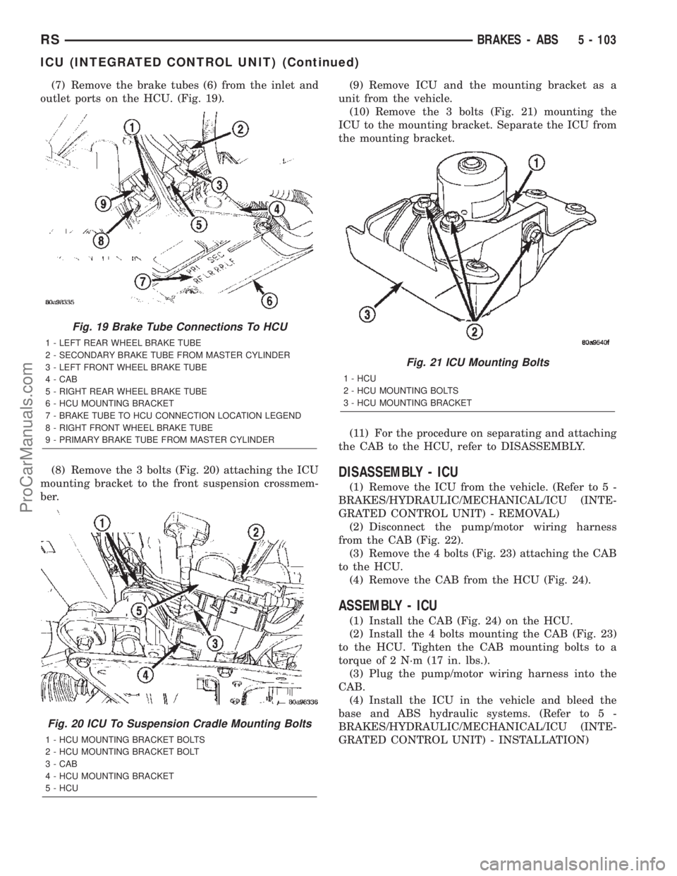
(7) Remove the brake tubes (6) from the inlet and
outlet ports on the HCU. (Fig. 19).
(8) Remove the 3 bolts (Fig. 20) attaching the ICU
mounting bracket to the front suspension crossmem-
ber.(9) Remove ICU and the mounting bracket as a
unit from the vehicle.
(10) Remove the 3 bolts (Fig. 21) mounting the
ICU to the mounting bracket. Separate the ICU from
the mounting bracket.
(11) For the procedure on separating and attaching
the CAB to the HCU, refer to DISASSEMBLY.
DISASSEMBLY - ICU
(1) Remove the ICU from the vehicle. (Refer to 5 -
BRAKES/HYDRAULIC/MECHANICAL/ICU (INTE-
GRATED CONTROL UNIT) - REMOVAL)
(2) Disconnect the pump/motor wiring harness
from the CAB (Fig. 22).
(3) Remove the 4 bolts (Fig. 23) attaching the CAB
to the HCU.
(4) Remove the CAB from the HCU (Fig. 24).
ASSEMBLY - ICU
(1) Install the CAB (Fig. 24) on the HCU.
(2) Install the 4 bolts mounting the CAB (Fig. 23)
to the HCU. Tighten the CAB mounting bolts to a
torque of 2 N´m (17 in. lbs.).
(3) Plug the pump/motor wiring harness into the
CAB.
(4) Install the ICU in the vehicle and bleed the
base and ABS hydraulic systems. (Refer to 5 -
BRAKES/HYDRAULIC/MECHANICAL/ICU (INTE-
GRATED CONTROL UNIT) - INSTALLATION)
Fig. 19 Brake Tube Connections To HCU
1 - LEFT REAR WHEEL BRAKE TUBE
2 - SECONDARY BRAKE TUBE FROM MASTER CYLINDER
3 - LEFT FRONT WHEEL BRAKE TUBE
4 - CAB
5 - RIGHT REAR WHEEL BRAKE TUBE
6 - HCU MOUNTING BRACKET
7 - BRAKE TUBE TO HCU CONNECTION LOCATION LEGEND
8 - RIGHT FRONT WHEEL BRAKE TUBE
9 - PRIMARY BRAKE TUBE FROM MASTER CYLINDER
Fig. 20 ICU To Suspension Cradle Mounting Bolts
1 - HCU MOUNTING BRACKET BOLTS
2 - HCU MOUNTING BRACKET BOLT
3 - CAB
4 - HCU MOUNTING BRACKET
5 - HCU
Fig. 21 ICU Mounting Bolts
1 - HCU
2 - HCU MOUNTING BOLTS
3 - HCU MOUNTING BRACKET
RSBRAKES - ABS5 - 103
ICU (INTEGRATED CONTROL UNIT) (Continued)
ProCarManuals.com
Page 233 of 2399
INSTALLATION
INSTALLATION - LHD
(1) Place the ICU in its bracket below the master
cylinder. Start the upper mounting bolt to hold it in
place.
(2) Inside the vehicle, install the remaining 2
mounting bolts attaching the ICU to the mounting
bracket (Fig. 16). Tighten all 3 mounting bolts to a
torque of 11 N´m (97 in. lbs.).
(3) Install the dash seal and three mounting
screws (Fig. 15).(4) Install the silencer on top of the dash seal (Fig.
15).
(5) Connect the steering shaft coupling and install
the pinch bolt (Fig. 15). Tighten the pinch bolt to 28
N´m (250 in. lbs.).
(6) Install the silencer panel below the steering
column under the instrument panel.
(7) Remove the steering wheel holder.
CAUTION: Because of the flexible section in the pri-
mary and secondary brake tubes, the brake tubes
must be held in proper orientation when tightened
and torqued. These tubes must not contact each
other or other vehicle components when installed.
Also, after the brake tubes are installed on the HCU,
ensure all spacer clips are reinstalled on the brake
tubes.
(8) Install the primary and secondary brake tubes
into their correct port locations on the HCU valve
block (Fig. 14). Tighten the tube nuts to a torque of
17 N´m (145 in. lbs.).
CAUTION: When installing the chassis brake tubes
on the HCU valve block, they must be located cor-
rectly in the valve block to ensure proper ABS oper-
ation.
NOTE: The chassis brake tube attachment locations
to the HCU, are marked on the bottom of the CAB.
(9) Install the (4) chassis brake tubes into their
correct port locations on the HCU valve block as
shown (Fig. 14). Tighten the tube nuts to a torque of
17 N´m (145 in. lbs.).
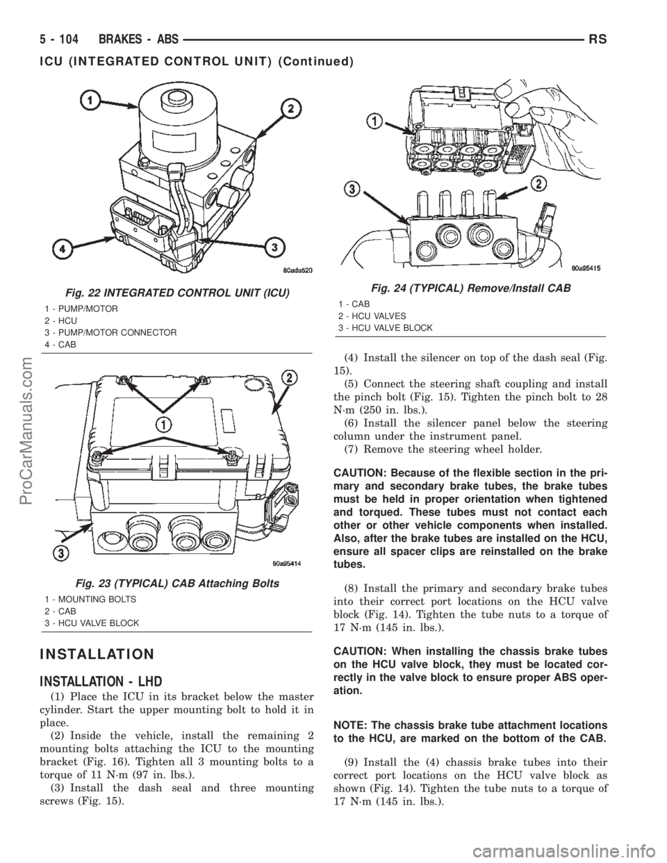
Fig. 22 INTEGRATED CONTROL UNIT (ICU)
1 - PUMP/MOTOR
2 - HCU
3 - PUMP/MOTOR CONNECTOR
4 - CAB
Fig. 23 (TYPICAL) CAB Attaching Bolts
1 - MOUNTING BOLTS
2 - CAB
3 - HCU VALVE BLOCK
Fig. 24 (TYPICAL) Remove/Install CAB
1 - CAB
2 - HCU VALVES
3 - HCU VALVE BLOCK
5 - 104 BRAKES - ABSRS
ICU (INTEGRATED CONTROL UNIT) (Continued)
ProCarManuals.com