2002 CHRYSLER TOWN AND COUNTRY Engine ground
[x] Cancel search: Engine groundPage 21 of 2399

(2) When using another vehicle as a booster
source, park the booster vehicle within cable reach.
Turn off all accessories, set the parking brake, place
the automatic transmission in PARK or the manual
transmission in NEUTRAL and turn the ignition
OFF.
(3) On disabled vehicle, place gear selector in park
or neutral and set park brake. Turn off all accesso-
ries.
(4) Connect jumper cables to booster battery. RED
clamp to positive terminal (+). BLACK clamp to neg-
ative terminal (-). DO NOT allow clamps at opposite
end of cables to touch, electrical arc will result.
Review all warnings in this procedure.
(5) On disabled vehicle, connect RED jumper cable
clamp to positive (+) terminal. Connect BLACK
jumper cable clamp to engine ground as close to the
ground cable attaching point as possible (Fig. 6).
(Refer to 8 - ELECTRICAL/BATTERY SYSTEM/BAT-
TERY - STANDARD PROCEDURE).
(6) Start the engine in the vehicle which has the
booster battery, let the engine idle a few minutes,
then start the engine in the vehicle with the dis-
charged battery.
CAUTION: Do not crank starter motor on disabled
vehicle for more than 15 seconds, starter may over-
heat and could fail.
(7) If engine does not start within 15 seconds, stop
cranking engine and allow starter to cool (15 min-
utes), before cranking again.DISCONNECT CABLE CLAMPS AS FOLLOWS:
²Disconnect BLACK cable clamp from engine
ground on disabled vehicle.
²When using a Booster vehicle, disconnect
BLACK cable clamp from battery negative terminal.
Disconnect RED cable clamp from battery positive
terminal.
²Disconnect RED cable clamp from battery posi-
tive terminal on disabled vehicle.
TOWING
STANDARD PROCEDURE - TOWING
WARNINGS AND CAUTIONS
WARNING: DO NOT ALLOW TOWING ATTACHMENT
DEVICES TO CONTACT THE FUEL TANK OR LINES,
FUEL LEAK CAN RESULT.
DO NOT LIFT OR TOW VEHICLE BY FRONT OR
REAR BUMPER.
DO NOT GO UNDER A LIFTED VEHICLE IF NOT
SUPPORTED PROPERLY ON SAFETY STANDS.
DO NOT ALLOW PASSENGERS TO RIDE IN A
TOWED VEHICLE.
USE A SAFETY CHAIN THAT IS INDEPENDENT
FROM THE TOWING ATTACHMENT DEVICE.
CAUTION: Do not damage brake lines, exhaust sys-
tem, shock absorbers, sway bars, or any other
under vehicle components when attaching towing
device to vehicle.
Do not secure vehicle to towing device by the use
of front or rear suspension or steering components.
Remove or secure loose or protruding objects from
a damaged vehicle before towing.
Refer to state and local rules and regulations before
towing a vehicle.
Do not allow weight of towed vehicle to bear on
lower fascia, air dams, or spoilers.
RECOMMENDED TOWING EQUIPMENT
To avoid damage to bumper fascia and air dams
use:
²FWD vehicles, use of a flat bed towing device or
a wheel lift is recommended (Fig. 7).
²AWD vehicles, a flat bed towing device or a
wheel lift and towing dolly is recommended (Fig. 7).
When using a wheel lift towing device, be sure the
disabled vehicle has at least 100 mm (4 in.) ground
clearance. If minimum ground clearance cannot be
reached, use a towing dolly. If a flat bed device is
used, the approach angle should not exceed 15
degrees.
Fig. 6 JUMPER CABLE CLAMP CONNECTIONS
1 - BATTERY NEGATIVE TERMINAL
2 - POSITIVE JUMPER CABLE
3 - TEST INDICATOR (IF EQUIPPED)
4 - BATTERY POSITIVE TERMINAL
5 - BATTERY
6 - NEGATIVE JUMPER CABLE
0 - 8 LUBRICATION & MAINTENANCERS
JUMP STARTING (Continued)
ProCarManuals.com
Page 22 of 2399

GROUND CLEARANCE
CAUTION: If vehicle is towed with wheels removed,
install lug nuts to retain brake drums or rotors.
A towed vehicle should be raised until the lifted
wheels are a minimum 100 mm (4 in.) from the
ground. Be sure there is at least 100 mm (4 in.)
clearance between the tail pipe and the ground. If
necessary, remove the wheels from the front end of
the vehicle and lower the front end closer to the
ground, to increase the ground clearance at the rear
of the vehicle. Install lug nuts on wheel attaching
studs to retain brake drums or rotors.
LOCKED VEHICLE TOWING
When a locked vehicle must be towed with the
front wheels on the ground, use a towing dolly or flat
bed hauler.
FLAT TOWING WITH TOW BAR
²Three speed automatic transaxle vehicles can be
flat towed at speeds not to exceed 40 km/h (25 mph)
for not more than 25 km (15 miles). The steering col-
umn must be unlocked and gear selector in neutral.
²Four speed electronic automatic transaxle vehi-
cles can be flat towed at speeds not to exceed 72
km/h (44 mph) for not more than 160 km (100 miles).
The steering column must be unlocked and gear
selector in neutral.
²AWD models should not be flat towed. For addi-
tional information, refer toRECOMMENDED TOW-
ING EQUIPMENTin this section.
FLAT BED TOWING TIE DOWNS
CAUTION: Do not tie vehicle down by attaching
chains or cables to suspension components or
engine mounts, damage to vehicle can result.
The vehicle can be tied to a flat bed device using
the two pair of front slots on the bottom surface of
the rails, behind the front wheels. The two pair of
rear slots on the bottom of the rail between the
bumper extension bolts and on the bottom of the rail
just rearward of the jounce bumper. Vehicles
equipped with a rear sway bar have brackets at this
location.
TOWING ± FRONT WHEEL LIFT
If the vehicle is being towed from the front, when-
ever possible ensure at least 10 inches road clearance
to the tires.
TOWING ± REAR WHEEL LIFT
If a vehicle cannot be towed with the front wheels
lifted, the rear wheels can be lifted provided the fol-
lowing guide lines are observed.
CAUTION: Do not use steering column lock to
secure steering wheel during towing operation.
²On AWD vehicles, all four wheels must be free to
rotate. Use towing dollies at unlifted end of vehicle.
²Unlock steering column and secure steering
wheel in straight ahead position with a clamp device
designed for towing.
²Three speed automatic transaxle vehicles can be
flat towed at speeds not to exceed 40 km/h (25 mph)
for not more than 25 km (15 miles). The steering col-
umn must be unlocked and gear selector in neutral.
²Four speed electronic automatic transaxle vehi-
cles can be flat towed at speeds not to exceed 72
km/h (44 mph) for not more than 160 km (100 miles).
The steering column must be unlocked and gear
selector in neutral.
Fig. 7 RECOMMENDED TOWING
1 - WHEEL LIFT
2 - FLAT BED
RSLUBRICATION & MAINTENANCE0-9
TOWING (Continued)
ProCarManuals.com
Page 72 of 2399

THRUST ANGLE
Thrust angle is the averaged direction the rear
wheels are pointing in relation to the vehicle's center
line (Fig. 6). The presence of negative or positive
thrust angle causes the rear tires to track improperly
to the left or right of the front tires (dog tracking).
²Negative thrust angle means the rear tires are
tracking to the left of the front tires.
²Positive thrust angle means the rear tires are
tracking to the right of the front tires.
Improper tracking can cause undue tire wear, a
lead or pull and a crooked steering wheel. Excessive
thrust angle can usually be corrected by adjusting
the rear wheel toe so that each wheel has one-half of
the total toe measurement.
DIAGNOSIS AND TESTING - SUSPENSION AND STEERING
CONDITION POSSIBLE CAUSES CORRECTION
Front End Whine On Turns 1. Defective wheel bearing 1. Replace wheel bearing
2. Incorrect wheel alignment 2. Check and reset wheel alignment
3. Worn tires 3. Replace tires
Front End Growl Or
Grinding On Turns1. Defective wheel bearing 1. Replace wheel bearing
2. Engine mount grounding 2. Check for motor mount hitting frame rail
and reposition engine as required
3. Worn or broken C/V joint 3. Replace C/V joint
4. Loose wheel lug nuts 4. Verify wheel lug nut torque
5. Incorrect wheel alignment 5. Check and reset wheel alignment
6. Worn tires 6. Replace tires
7. Front strut pin in upper strut mount 7. Replace the front strut upper mount and
bearing
Front End Clunk Or Snap
On Turns1. Loose lug nuts 1. Verify wheel lug nut torque
2. Worn or broken C/V joint 2. Replace C/V joint
3. Worn or loose tie rod 3. Tighten or replace tie rod end
4. Worn or loose ball joint 4. Tighten or replace ball joint
5. Worn/loose control arm bushing 5. Replace control arm bushing
6. Loose stabilizer bar. 6. Tighten stabilizer bar to specified torque
Fig. 6 Thrust Angle
RSWHEEL ALIGNMENT2-49
WHEEL ALIGNMENT (Continued)
ProCarManuals.com
Page 73 of 2399

CONDITION POSSIBLE CAUSES CORRECTION
7. Loose strut mount to body
attachment7. Tighten strut attachment to specified
torque
8. Loose crossmember bolts 8. Tighten crossmember bolts to specified
torque
Front End Whine With
Vehicle Going Straight At A
Constant Speed1. Defective wheel bearing 1. Replace wheel bearing
2. Incorrect wheel alignment 2. Check and reset wheel alignment
3. Worn tires 3. Replace tires
4. Worn or defective transaxle gears
or bearings4. Replace transaxle gears or bearings
Front End Growl Or
Grinding With Vehicle
Going Straight At A
Constant Speed1. Engine mount grounding 1. Reposition engine as required
2. Worn or broken C/V joint 2. Replace C/V joint
Front End Whine When
Accelerating Or
Decelerating1. Worn or defective transaxle gears
or bearings1. Replace transaxle gears or bearings
Front End Clunk When
Accelerating Or
Decelerating1. Worn or broken engine mount 1. Replace engine mount
2. Worn or defective transaxle gears
or bearings2. Replace transaxle gears or bearings
3. Loose lug nuts 3. Verify wheel lug nut torque
4. Worn or broken C/V joint 4. Replace C/V joint
5. Worn or loose ball joint 5. Tighten or replace ball joint
6. Worn or loose control arm bushing 6. Replace control arm bushing
7. Loose crossmember bolts 7. Tighten crossmember bolts to specified
torque
8. Worn tie rod end 8. Replace tie rod end
Road Wander 1. Incorrect tire pressure 1. Inflate tires to recommended pressure
2. Incorrect front or rear wheel toe 2. Check and reset wheel toe
3. Worn wheel bearings 3. Replace wheel bearing
4. Worn control arm bushings 4. Replace control arm bushing
5. Excessive friction in steering gear 5. Replace steering gear
6. Excessive friction in steering shaft
coupling6. Replace steering coupler
7. Excessive friction in strut upper
bearing7. Replace strut bearing
Lateral Pull 1. Unequal tire pressure 1. Inflate all tires to recommended
pressure
2. Radial tire lead 2. Perform lead correction procedure
2 - 50 WHEEL ALIGNMENTRS
WHEEL ALIGNMENT (Continued)
ProCarManuals.com
Page 176 of 2399

(27) Install lower steering column cover/knee
blocker (Fig. 62).
(28) Install silencer panel below lower steering col-
umn cover/knee blocker.
NOTE: When reconnecting the battery on a vehicle
that has had the airbag module removed, the fol-
lowing procedure should be used.
(29) Reconnect ground cable to negative post of
battery in following manor:
(a) Connect scan tool (DRBIIIt) to data link
diagnostic connector located below steering column.
(b) Turn ignition key to ON position. Exit vehi-
cle with scan tool leaving scan tool harness
plugged in.
(c) Ensuring that there are no occupants in vehi-
cle, connect ground (-) cable to the negative post of
the battery.
(d) Using scan tool, read and record any airbag
fault codes. Refer to Appropriate Diagnostic Infor-
mation if any faults are found.
(e) Through drivers open window, Reach around
back of steering wheel (between steering wheel and
instrument cluster) and turn ignition key to OFF,
then back ON while observing instrument cluster
airbag indicator lamp. It should go on for six to
eight seconds, then go out. This action indicates
that airbag system is functioning normally. If air-
bag indicator lamp fails to light, blinks on and off,
or goes on and stays on, there is an airbag system
malfunction. Refer to Appropriate Diagnostic Infor-
mation to diagnose the system malfunction.
(30) Using scan tool (DRBIIIt), check for and clear
any existing adjustable pedal fault codes. The adjust-
able pedal system is now activated.
(31) Turn key to OFF and remove scan tool from
vehicle.
(32) Test operation of adjustable pedals, memory
seats (if equipped), RKE (if equipped), and all func-
tions that are steering column operated. If applica-
ble, reset the radio and the clock.
(33) Road test the vehicle to ensure proper opera-
tion of the steering and brake systems.
PEDAL TORQUE SHAFT - RHD
REMOVAL
(1) Remove the instrument panel. (Refer to 23 -
BODY/INSTRUMENT PANEL/INSTRUMENT
PANEL ASSEMBLY - REMOVAL)
(2) Remove the HVAC housing. (Refer to 24 -
HEATING & AIR CONDITIONING/DISTRIBUTION/
HVAC HOUSING - REMOVAL)
(3) Remove the retaining clip at the torque shaft
end of the brake pedal-to-torque shaft link. Removethe link from the torque shaft. Discard the retaining
clip. It is not to be reused. Replace with a new clip
when reassembled.
(4) Locate the booster input rod-to-brake pedal
torque shaft connection and remove the retaining clip
(Fig. 73). Discard the retaining clip. It is not to be
reused. Replace with a new clip when reassembled.
(5) Remove the four (4) brake booster retaining
nuts from inside the passenger compartment (Fig.
74).
(6) Remove the retaining nut from the brake
booster bracket located above the booster in the
engine compartment (Fig. 74).
(7) Remove the power brake booster bracket.
(8) Rotate the pedal torque shaft and remove it out
the left side of the vehicle.
INSTALLATION
(1) Lubricate both ends of the torque shaft with
MS-4517 Lubricant or equivalent and install the
torque shaft from the left side reversing the removal
procedure.
(2) Install the brake booster bracket on the left
end of the shaft.
(3) Install the four brake booster retaining nuts
inside the passenger compartment. Tighten the
mounting nuts to a torque of 29 N´m (250 in. lbs.).
(4) Install the retaining nut for the brake booster
bracket in the engine compartment. Tighten the
mounting nuts to a torque of 29 N´m (250 in. lbs.).
(5) Using lubriplate, or equivalent, coat the sur-
face of the brake pedal torque shaft pin where it con-
tacts the booster input rod. Also coat the surface of
Fig. 73 POWER BRAKE BOOSTER BRACKET
1 - BOOSTER BRACKET
2 - PEDAL TORQUE SHAFT
3 - RETAINING CLIP
4 - BOOSTER MOUNTING NUTS
RSBRAKES - BASE5-47
PEDAL - ADJUSTABLE (Continued)
ProCarManuals.com
Page 229 of 2399
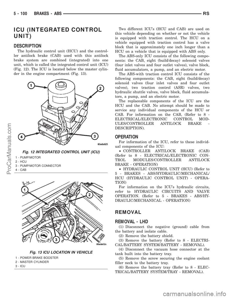
ICU (INTEGRATED CONTROL
UNIT)
DESCRIPTION
The hydraulic control unit (HCU) and the control-
ler antilock brake (CAB) used with this antilock
brake system are combined (integrated) into one
unit, which is called the integrated control unit (ICU)
(Fig. 12). The ICU is located below the master cylin-
der in the engine compartment (Fig. 13).Two different ICU's (HCU and CAB) are used on
this vehicle depending on whether or not the vehicle
is equipped with traction control. The HCU on a
vehicle equipped with traction control has a valve
block that is approximately one inch longer than a
HCU on a vehicle that is equipped with ABS only.
The ABS-only ICU consists of the following compo-
nents: the CAB, eight (build/decay) solenoid valves
(four inlet valves and four outlet valves), valve block,
fluid accumulators, a pump, and an electric motor.
The ABS-with traction control ICU consists of the
following components: the CAB, eight (build/decay)
solenoid valves (four inlet valves and four outlet
valves), two traction control (ASR) valves, two
hydraulic shuttle valves, valve block, fluid accumula-
tors, a pump, and an electric motor.
The replaceable components of the ICU are the
HCU and the CAB. No attempt should be made to
service any individual components of the HCU or
CAB. For information on the CAB, (Refer to 8 -
ELECTRICAL/ELECTRONIC CONTROL MOD-
ULES/CONTROLLER ANTILOCK BRAKE -
DESCRIPTION).
OPERATION
For information of the ICU, refer to these individ-
ual components of the ICU:
²CONTROLLER ANTILOCK BRAKE (CAB)
(Refer to 8 - ELECTRICAL/ELECTRONIC CON-
TROL MODULES/CONTROLLER ANTILOCK
BRAKE - OPERATION)
²HYDRAULIC CONTROL UNIT (HCU) (Refer to
5 - BRAKES - ABS/HYDRAULIC/MECHANICAL/
HCU (HYDRAULIC CONTROL UNIT) - OPERA-
TION)
For information on the ICU's hydraulic circuits,
refer to HYDRAULIC CIRCUITS AND VALVE
OPERATION. (Refer to 5 - BRAKES - ABS/HY-
DRAULIC/MECHANICAL - OPERATION)
REMOVAL
REMOVAL - LHD
(1) Disconnect the negative (ground) cable from
the battery and isolate cable.
(2) Remove the battery shield.
(3) Remove the battery (Refer to 8 - ELECTRI-
CAL/BATTERY SYSTEM/BATTERY - REMOVAL).
(4) Disconnect the vacuum hose connector at the
tank built into the battery tray.
(5) Remove the screw securing the engine coolant
filler neck to the battery tray.
(6) Remove the battery tray (Refer to 8 - ELEC-
TRICAL/BATTERY SYSTEM/TRAY - REMOVAL).
Fig. 12 INTEGRATED CONTROL UNIT (ICU)
1 - PUMP/MOTOR
2 - HCU
3 - PUMP/MOTOR CONNECTOR
4 - CAB
Fig. 13 ICU LOCATION IN VEHICLE
1 - POWER BRAKE BOOSTER
2 - MASTER CYLINDER
3 - ICU
5 - 100 BRAKES - ABSRS
ProCarManuals.com
Page 230 of 2399
(7) Using a brake pedal depressor, move and lock
the brake pedal to a position past the first inch of
pedal travel.This will prevent brake fluid from
draining out of the master cylinder once the
brake tubes are removed from the HCU.
CAUTION: Do not apply a 12±volt power source to
any terminals of the 24-way CAB connector when
disconnected.
(8) Disconnect the wiring harness connector from
the speed control servo.
(9) Remove the speed control servo mounting nuts
and move the servo out of the way.
(10) Disconnect the 24±way connector from the
CAB. To disconnect the 24±way connector, grasp the
lock on the 24±way connector and pull it as far up as
possible. This will unlock the 24±way connector from
the socket on the CAB.
CAUTION: Before removing the brake tubes from
the HCU, the HCU must be thoroughly cleaned. This
must be done to prevent dirt particles from falling
into the ports of HCU or entering the brake tubes.
(11) Thoroughly clean all surfaces of the ICU and
brake tube nuts. Use only a solvent such as Mopart
Brake Parts Cleaner or equivalent to clean the ICU.
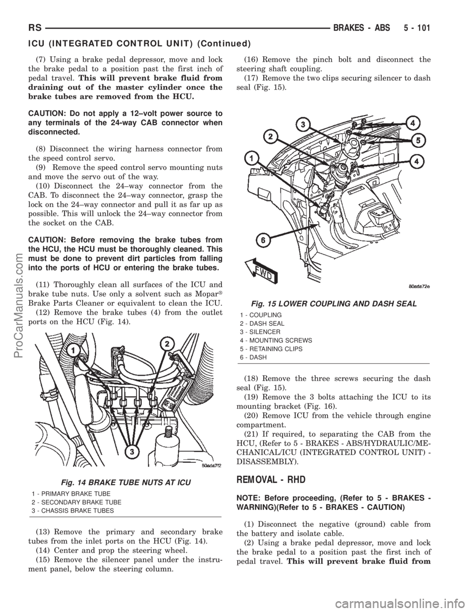
(12) Remove the brake tubes (4) from the outlet
ports on the HCU (Fig. 14).
(13) Remove the primary and secondary brake
tubes from the inlet ports on the HCU (Fig. 14).
(14) Center and prop the steering wheel.
(15) Remove the silencer panel under the instru-
ment panel, below the steering column.(16) Remove the pinch bolt and disconnect the
steering shaft coupling.
(17) Remove the two clips securing silencer to dash
seal (Fig. 15).
(18) Remove the three screws securing the dash
seal (Fig. 15).
(19) Remove the 3 bolts attaching the ICU to its
mounting bracket (Fig. 16).
(20) Remove ICU from the vehicle through engine
compartment.
(21) If required, to separating the CAB from the
HCU, (Refer to 5 - BRAKES - ABS/HYDRAULIC/ME-
CHANICAL/ICU (INTEGRATED CONTROL UNIT) -
DISASSEMBLY).
REMOVAL - RHD
NOTE: Before proceeding, (Refer to 5 - BRAKES -
WARNING)(Refer to 5 - BRAKES - CAUTION)
(1) Disconnect the negative (ground) cable from
the battery and isolate cable.
(2) Using a brake pedal depressor, move and lock
the brake pedal to a position past the first inch of
pedal travel.This will prevent brake fluid from
Fig. 14 BRAKE TUBE NUTS AT ICU
1 - PRIMARY BRAKE TUBE
2 - SECONDARY BRAKE TUBE
3 - CHASSIS BRAKE TUBES
Fig. 15 LOWER COUPLING AND DASH SEAL
1 - COUPLING
2 - DASH SEAL
3 - SILENCER
4 - MOUNTING SCREWS
5 - RETAINING CLIPS
6 - DASH
RSBRAKES - ABS5 - 101
ICU (INTEGRATED CONTROL UNIT) (Continued)
ProCarManuals.com
Page 264 of 2399

ENGINE
DIAGNOSIS AND TESTING - ENGINE COOLING
SYSTEM
Establish what driving condition caused the cooling
system complaint. The problem may be caused by an
abnormal load on the system such as the following:
prolonged idle, very high ambient temperature, slight
tail wind at idle, slow traffic speed, traffic jam, high
speed, steep grade.
DRIVING TECHNIQUES
To avoid overheating the cooling system:
(1) Idle with A/C off when temperature gauge is at
end of normal range.
(2) Do not increase engine speed for more air flow
and coolant flow because the electric motor fan sys-
tems are not responsive to engine RPM. The added
cooling from higher coolant flow rate is more than
offset by increased heat rejection (engine heat added
to coolant).
TRAILER TOWING
Consult the owner's manual under Trailer Towing
and do not exceed specified limits.
VISUAL INSPECTION
If the cooling system problem is not caused by a
driving condition, perform a visual inspection to
determine if there was a recent service or accident
repair, including the following:
²Loose/damaged water pump drive belt
²Incorrect cooling system refilling (trapped air or
low level)
²Brakes possibly dragging
²Damaged hoses
²Loose/damaged hose clamps
²Damaged/incorrect engine thermostat
²Damaged cooling fan motor, fan blade and fan
shroud
²Damaged head gasket
²Damaged water pump
²Damaged radiator
²Damaged coolant recovery system
²Damaged heater core
²Open/shorted electrical circuits
If the visual inspection reveals none of the above
as cause for a cooling system complaint, refer to the
following diagnostic charts.
COOLING SYSTEM DIAGNOSIS CHART
CONDITION POSSIBLE CAUSES CORRECTION
PRESSURE CAP IS BLOWING
OFF STEAM AND/OR COOLANT.
TEMPERATURE GAUGE READING
MAY BE ABOVE NORMAL BUT
NOT HIGH. COOLANT LEVEL MAY
BE HIGH IN COOLANT RESERVE/
OVERFLOW TANK.1. Pressure relief valve in radiator
cap is defective, or was not
properly seated.1. Check condition of radiator cap
and cap seal. (Refer to 7 -
COOLING/ENGINE/RADIATOR
PRESSURE CAP - DIAGNOSIS
AND TESTING) Replace cap as
necessary.
2. Incorrect cap was installed. 2. Replace cap as necessary.
3. Incorrect coolant mixture. 3. Check concentration level of the
coolant. (Refer to 7 - COOLING/
ENGINE/COOLANT - DIAGNOSIS
AND TESTING) Adjust the ethylene
glycol-to-water ratio as required.
COOLANT LOSS TO THE
GROUND WITHOUT PRESSURE
CAP BLOWOFF. GAUGE IS
READING HIGH OR HOT.1. Coolant leaks in radiator, cooling
system hoses, water pump or
engine.1. Pressure test and repair as
necessary. (Refer to 7 - COOLING -
DIAGNOSIS AND TESTING)
RSENGINE7-15
ProCarManuals.com