2002 CHRYSLER CARAVAN timing belt
[x] Cancel search: timing beltPage 1265 of 2399
(3) Install crankshaft vibration damper. (Refer to 9
- ENGINE/ENGINE BLOCK/VIBRATION DAMPER -
INSTALLATION)
TIMING BELT AND
SPROCKET(S)
REMOVAL
REMOVAL - TIMING BELT
(1) Remove air cleaner upper cover, housing, and
clean air tube.
(2) Remove make-up air hose from cylinder head
cover.
(3) Raise vehicle on hoist.
(4) Remove right front wheel.
(5) Remove right inner splash shield.
(6) Remove accessory drive belts. (Refer to 7 -
COOLING/ACCESSORY DRIVE/BELT TENSION-
ERS - REMOVAL)
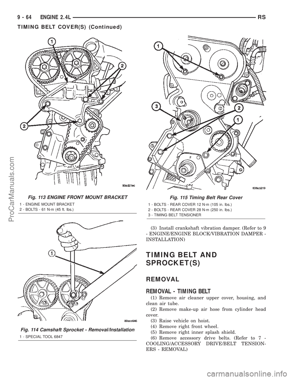
Fig. 113 ENGINE FRONT MOUNT BRACKET
1 - ENGINE MOUNT BRACKET
2 - BOLTS - 61 N´m (45 ft. lbs.)
Fig. 114 Camshaft Sprocket - Removal/Installation
1 - SPECIAL TOOL 6847
Fig. 115 Timing Belt Rear Cover
1 - BOLTS - REAR COVER 12 N´m (105 in. lbs.)
2 - BOLTS - REAR COVER 28 N´m (250 in. lbs.)
3 - TIMING BELT TENSIONER
9 - 64 ENGINE 2.4LRS
TIMING BELT COVER(S) (Continued)
ProCarManuals.com
Page 1266 of 2399
(7) Remove crankshaft vibration damper. (Refer to
9 - ENGINE/ENGINE BLOCK/VIBRATION
DAMPER - REMOVAL)
(8) Remove air conditioner/generator belt tensioner
and pulley assembly. (Refer to 7 - COOLING/ACCES-
SORY DRIVE/BELT TENSIONERS - REMOVAL)
(9) Remove timing belt lower front cover bolts and
remove cover. (Refer to 9 - ENGINE/VALVE TIMING/
TIMING BELT / CHAIN COVER(S) - REMOVAL)
(10) Lower vehicle.
(11) Remove bolts attaching timing belt upper
front cover and remove cover. (Refer to 9 - ENGINE/
VALVE TIMING/TIMING BELT / CHAIN COVER(S)
- REMOVAL)
(12) Remove right engine mount. (Refer to 9 -
ENGINE/ENGINE MOUNTING/RIGHT MOUNT -
REMOVAL)
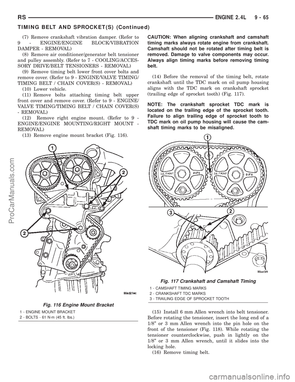
(13) Remove engine mount bracket (Fig. 116).CAUTION: When aligning crankshaft and camshaft
timing marks always rotate engine from crankshaft.
Camshaft should not be rotated after timing belt is
removed. Damage to valve components may occur.
Always align timing marks before removing timing
belt.
(14) Before the removal of the timing belt, rotate
crankshaft until the TDC mark on oil pump housing
aligns with the TDC mark on crankshaft sprocket
(trailing edge of sprocket tooth) (Fig. 117).
NOTE: The crankshaft sprocket TDC mark is
located on the trailing edge of the sprocket tooth.
Failure to align trailing edge of sprocket tooth to
TDC mark on oil pump housing will cause the cam-
shaft timing marks to be misaligned.
(15) Install 6 mm Allen wrench into belt tensioner.
Before rotating the tensioner, insert the long end of a
1/8º or 3 mm Allen wrench into the pin hole on the
front of the tensioner (Fig. 118). While rotating the
tensioner counterclockwise, push in lightly on the
1/8º or 3 mm Allen wrench, until it slides into the
locking hole.
(16) Remove timing belt.
Fig. 116 Engine Mount Bracket
1 - ENGINE MOUNT BRACKET
2 - BOLTS - 61 N´m (45 ft. lbs.)
Fig. 117 Crankshaft and Camshaft Timing
1 - CAMSHAFT TIMING MARKS
2 - CRANKSHAFT TDC MARKS
3 - TRAILING EDGE OF SPROCKET TOOTH
RSENGINE 2.4L9-65
TIMING BELT AND SPROCKET(S) (Continued)
ProCarManuals.com
Page 1267 of 2399
REMOVAL - CRANKSHAFT SPROCKET
(1) Disconnect negative battery cable.
(2) Remove timing belt (Refer to 9 - ENGINE/
VALVE TIMING/TIMING BELT/CHAIN AND
SPROCKETS - REMOVAL).
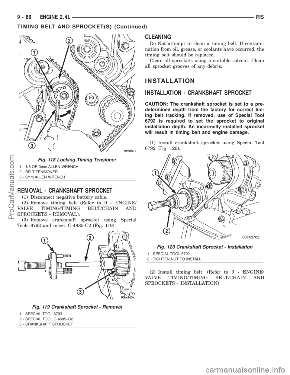
(3) Remove crankshaft sprocket using Special
Tools 6793 and insert C-4685-C2 (Fig. 119).
CLEANING
Do Not attempt to clean a timing belt. If contami-
nation from oil, grease, or coolants have occurred, the
timing belt should be replaced.
Clean all sprockets using a suitable solvent. Clean
all sprocket grooves of any debris.
INSTALLATION
INSTALLATION - CRANKSHAFT SPROCKET
CAUTION: The crankshaft sprocket is set to a pre-
determined depth from the factory for correct tim-
ing belt tracking. If removed, use of Special Tool
6792 is required to set the sprocket to original
installation depth. An incorrectly installed sprocket
will result in timing belt and engine damage.
(1) Install crankshaft sprocket using Special Tool
6792 (Fig. 120).
(2) Install timing belt. (Refer to 9 - ENGINE/
VALVE TIMING/TIMING BELT/CHAIN AND
SPROCKETS - INSTALLATION)
Fig. 118 Locking Timing Tensioner
1 - 1/8 OR 3mm ALLEN WRENCH
2 - BELT TENSIONER
3 - 6mm ALLEN WRENCH
Fig. 119 Crankshaft Sprocket - Removal
1 - SPECIAL TOOL 6793
2 - SPECIAL TOOL C-4685±C2
3 - CRANKSHAFT SPROCKET
Fig. 120 Crankshaft Sprocket - Installation
1 - SPECIAL TOOL 6792
2 - TIGHTEN NUT TO INSTALL
9 - 66 ENGINE 2.4LRS
TIMING BELT AND SPROCKET(S) (Continued)
ProCarManuals.com
Page 1268 of 2399
INSTALLATION - TIMING BELT
CAUTION: The crankshaft sprocket is set to a pre-
determined depth from the factory for correct tim-
ing belt tracking. If removed, use of Special Tool
6792 is required to set the sprocket to original
installation depth. An incorrectly installed sprocket
will result in timing belt and engine damage.
(1) Set crankshaft sprocket to TDC by aligning the
sprocket with the arrow on the oil pump housing.
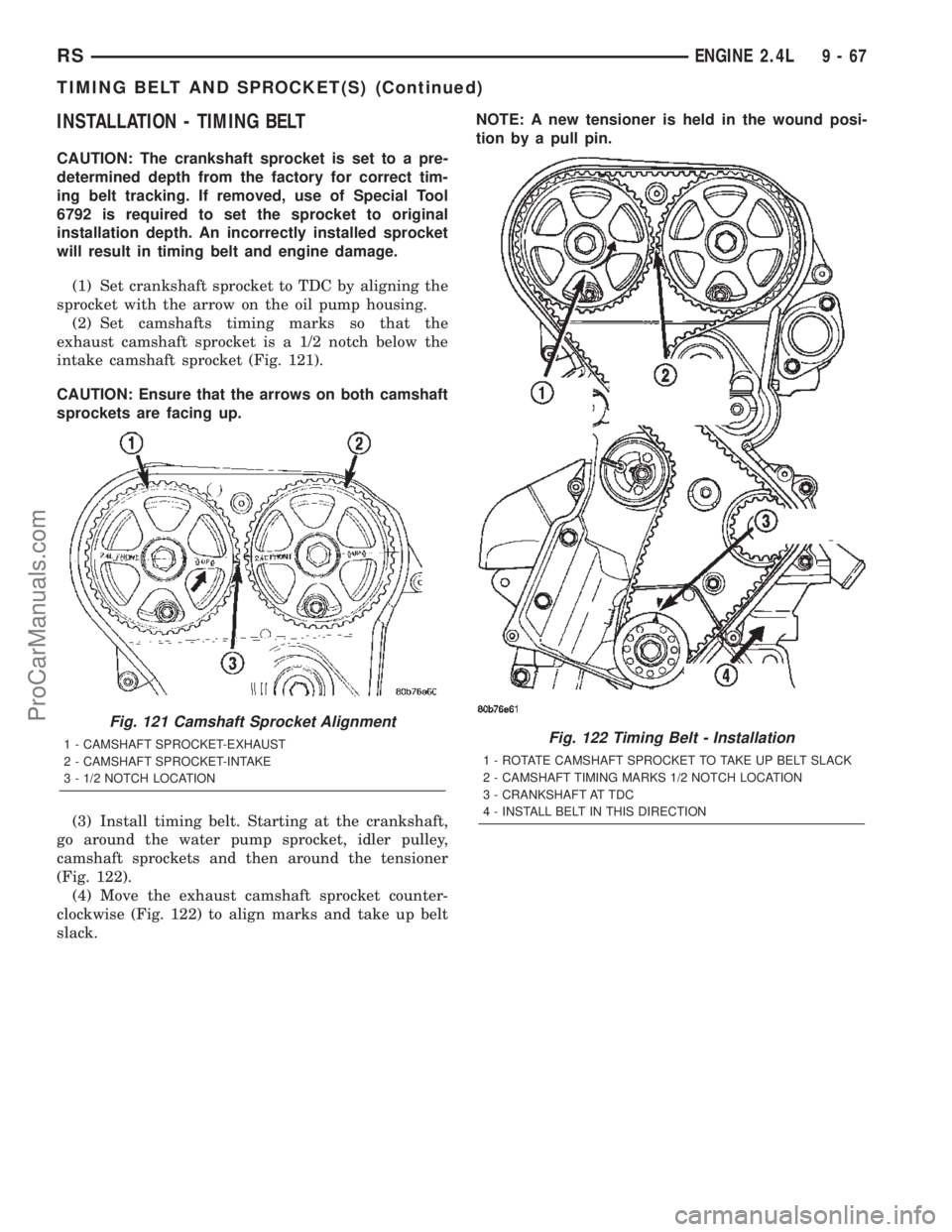
(2) Set camshafts timing marks so that the
exhaust camshaft sprocket is a 1/2 notch below the
intake camshaft sprocket (Fig. 121).
CAUTION: Ensure that the arrows on both camshaft
sprockets are facing up.
(3) Install timing belt. Starting at the crankshaft,
go around the water pump sprocket, idler pulley,
camshaft sprockets and then around the tensioner
(Fig. 122).
(4) Move the exhaust camshaft sprocket counter-
clockwise (Fig. 122) to align marks and take up belt
slack.NOTE: A new tensioner is held in the wound posi-
tion by a pull pin.
Fig. 121 Camshaft Sprocket Alignment
1 - CAMSHAFT SPROCKET-EXHAUST
2 - CAMSHAFT SPROCKET-INTAKE
3 - 1/2 NOTCH LOCATIONFig. 122 Timing Belt - Installation
1 - ROTATE CAMSHAFT SPROCKET TO TAKE UP BELT SLACK
2 - CAMSHAFT TIMING MARKS 1/2 NOTCH LOCATION
3 - CRANKSHAFT AT TDC
4 - INSTALL BELT IN THIS DIRECTION
RSENGINE 2.4L9-67
TIMING BELT AND SPROCKET(S) (Continued)
ProCarManuals.com
Page 1269 of 2399
(5) Remove the pull pin or Allen wrench from the
belt tensioner.
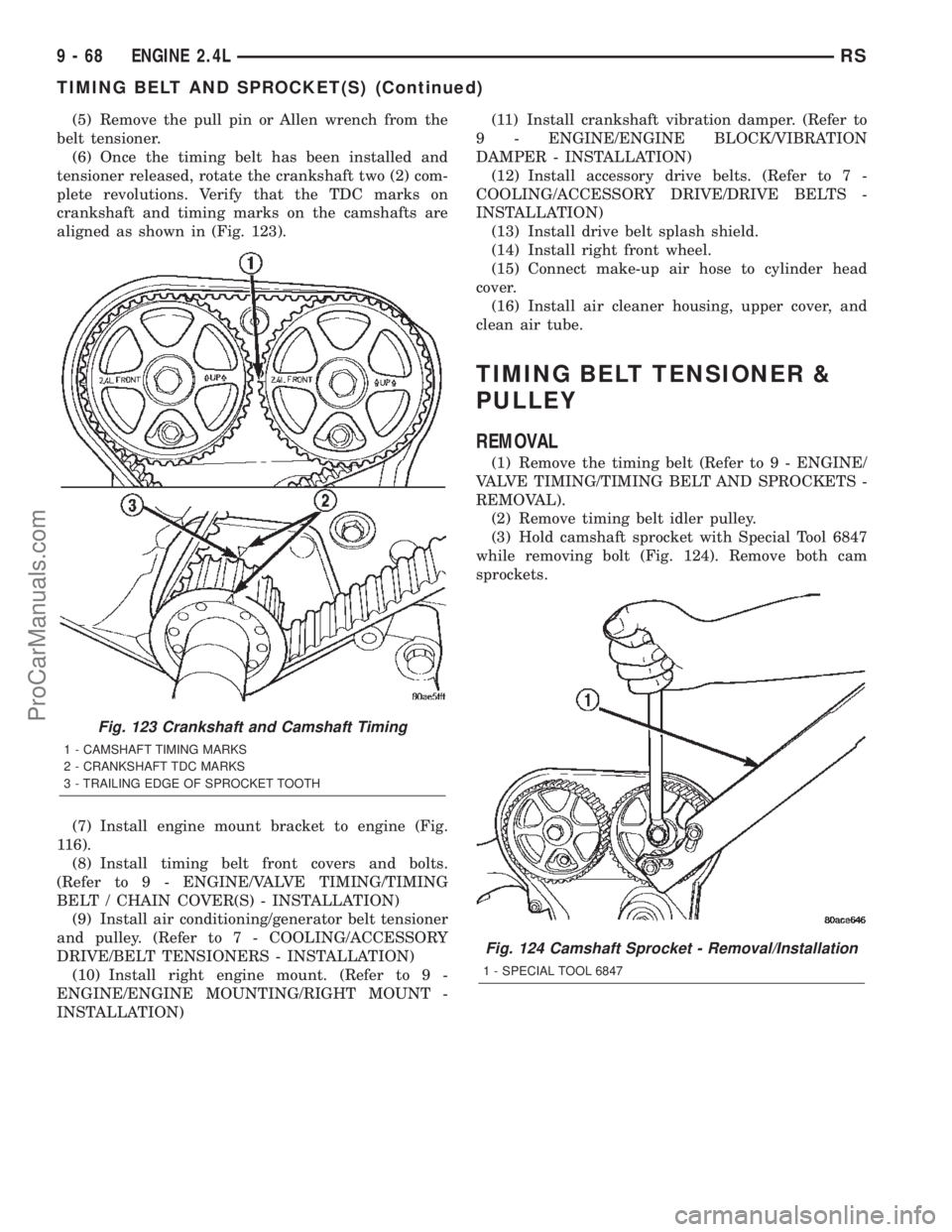
(6) Once the timing belt has been installed and
tensioner released, rotate the crankshaft two (2) com-
plete revolutions. Verify that the TDC marks on
crankshaft and timing marks on the camshafts are
aligned as shown in (Fig. 123).
(7) Install engine mount bracket to engine (Fig.
116).
(8) Install timing belt front covers and bolts.
(Refer to 9 - ENGINE/VALVE TIMING/TIMING
BELT / CHAIN COVER(S) - INSTALLATION)
(9) Install air conditioning/generator belt tensioner
and pulley. (Refer to 7 - COOLING/ACCESSORY
DRIVE/BELT TENSIONERS - INSTALLATION)
(10) Install right engine mount. (Refer to 9 -
ENGINE/ENGINE MOUNTING/RIGHT MOUNT -
INSTALLATION)(11) Install crankshaft vibration damper. (Refer to
9 - ENGINE/ENGINE BLOCK/VIBRATION
DAMPER - INSTALLATION)
(12) Install accessory drive belts. (Refer to 7 -
COOLING/ACCESSORY DRIVE/DRIVE BELTS -
INSTALLATION)
(13) Install drive belt splash shield.
(14) Install right front wheel.
(15) Connect make-up air hose to cylinder head
cover.
(16) Install air cleaner housing, upper cover, and
clean air tube.
TIMING BELT TENSIONER &
PULLEY
REMOVAL
(1) Remove the timing belt (Refer to 9 - ENGINE/
VALVE TIMING/TIMING BELT AND SPROCKETS -
REMOVAL).
(2) Remove timing belt idler pulley.
(3) Hold camshaft sprocket with Special Tool 6847
while removing bolt (Fig. 124). Remove both cam
sprockets.
Fig. 123 Crankshaft and Camshaft Timing
1 - CAMSHAFT TIMING MARKS
2 - CRANKSHAFT TDC MARKS
3 - TRAILING EDGE OF SPROCKET TOOTH
Fig. 124 Camshaft Sprocket - Removal/Installation
1 - SPECIAL TOOL 6847
9 - 68 ENGINE 2.4LRS
TIMING BELT AND SPROCKET(S) (Continued)
ProCarManuals.com
Page 1270 of 2399
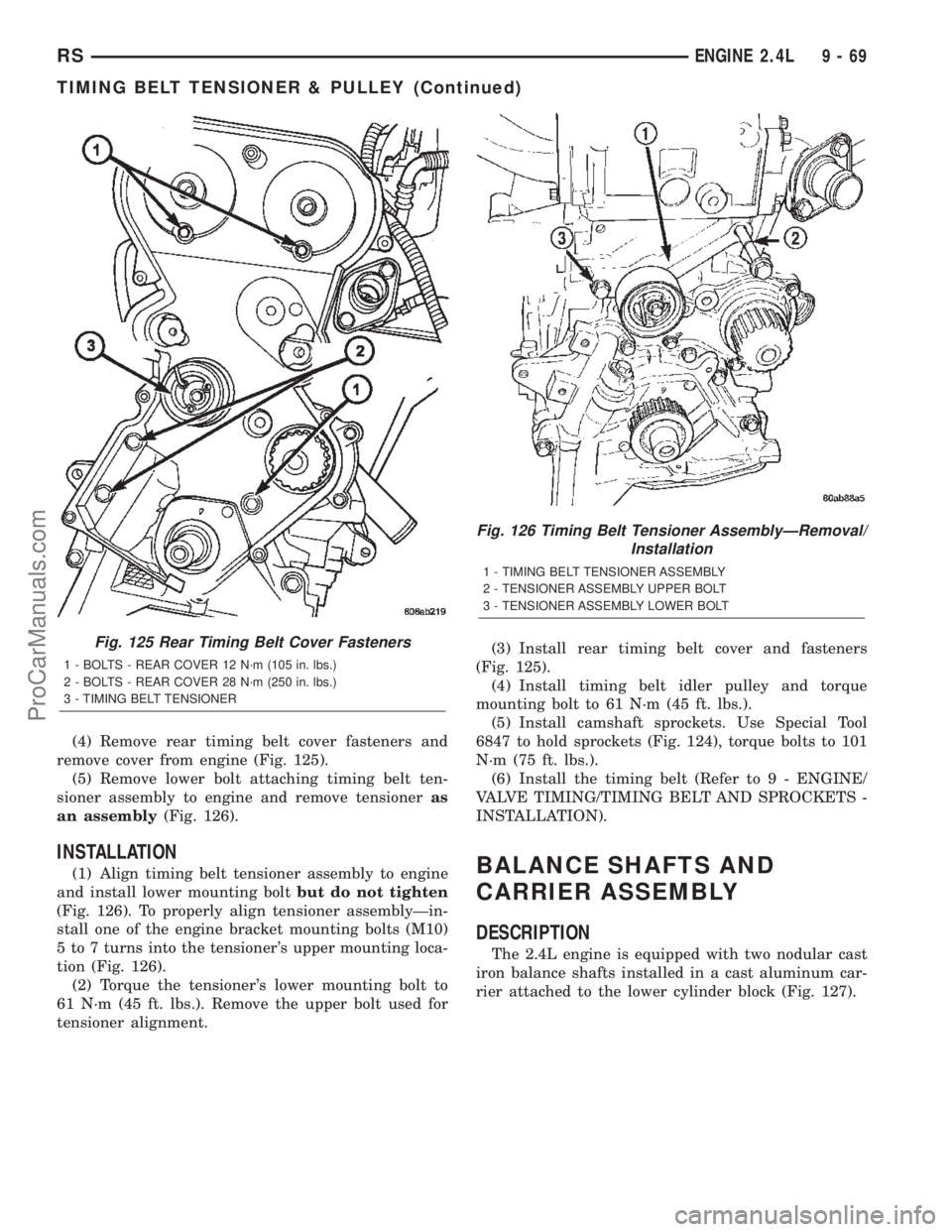
(4) Remove rear timing belt cover fasteners and
remove cover from engine (Fig. 125).
(5) Remove lower bolt attaching timing belt ten-
sioner assembly to engine and remove tensioneras
an assembly(Fig. 126).
INSTALLATION
(1) Align timing belt tensioner assembly to engine
and install lower mounting boltbut do not tighten
(Fig. 126). To properly align tensioner assemblyÐin-
stall one of the engine bracket mounting bolts (M10)
5 to 7 turns into the tensioner's upper mounting loca-
tion (Fig. 126).
(2) Torque the tensioner's lower mounting bolt to
61 N´m (45 ft. lbs.). Remove the upper bolt used for
tensioner alignment.(3) Install rear timing belt cover and fasteners
(Fig. 125).
(4) Install timing belt idler pulley and torque
mounting bolt to 61 N´m (45 ft. lbs.).
(5) Install camshaft sprockets. Use Special Tool
6847 to hold sprockets (Fig. 124), torque bolts to 101
N´m (75 ft. lbs.).
(6) Install the timing belt (Refer to 9 - ENGINE/
VALVE TIMING/TIMING BELT AND SPROCKETS -
INSTALLATION).BALANCE SHAFTS AND
CARRIER ASSEMBLY
DESCRIPTION
The 2.4L engine is equipped with two nodular cast
iron balance shafts installed in a cast aluminum car-
rier attached to the lower cylinder block (Fig. 127).
Fig. 125 Rear Timing Belt Cover Fasteners
1 - BOLTS - REAR COVER 12 N´m (105 in. lbs.)
2 - BOLTS - REAR COVER 28 N´m (250 in. lbs.)
3 - TIMING BELT TENSIONER
Fig. 126 Timing Belt Tensioner AssemblyÐRemoval/
Installation
1 - TIMING BELT TENSIONER ASSEMBLY
2 - TENSIONER ASSEMBLY UPPER BOLT
3 - TENSIONER ASSEMBLY LOWER BOLT
RSENGINE 2.4L9-69
TIMING BELT TENSIONER & PULLEY (Continued)
ProCarManuals.com
Page 1279 of 2399
DIAGNOSIS AND TESTING - ENGINE DIAGNOSIS - PERFORMANCE
CONDITION POSSIBLE CAUSE CORRECTION
ENGINE WILL NOT START 1. Weak battery. 1. Test battery. Charge or replace
as necessary. (Refer to 8 -
ELECTRICAL/BATTERY SYSTEM -
DIAGNOSIS AND TESTING)
2. Corroded or loose battery
connections.2. Clean and tighten battery
connections. Apply a coat of light
mineral grease to terminals.
3. Faulty starter. 3. Test starting system. (Refer to 8 -
ELECTRICAL/STARTING -
DIAGNOSIS AND TESTING)
4. Faulty coil(s) or control unit. 4. Test and replace as needed.
(Refer to Appropriate Diagnostic
Information)
5. Incorrect spark plug gap. 5. Set gap. (Refer to 8 -
ELECTRICAL/IGNITION CONTROL
- SPECIFICATIONS)
6. Contamination in fuel system. 6. Clean system and replace fuel
filter.
7. Faulty fuel pump. 7. Test fuel pump and replace as
needed. (Refer to Appropriate
Diagnostic Information)
8. Incorrect engine timing. 8. Check for a skipped timing
belt/chain.
ENGINE STALLS OR IDLES
ROUGH1. Idle speed too low. 1. Test minimum air flow. (Refer to
Appropriate Diagnostic Information)
2. Incorrect fuel mixture. 2. (Refer to Appropriate Diagnostic
Information)
3. Intake manifold leakage. 3. Inspect intake manifold, manifold
gasket, and vacuum hoses.
4. Faulty ignition coil(s). 4. Test and replace as necessary.
(Refer to Appropriate Diagnostic
Information)
9 - 78 ENGINE 3.3/3.8LRS
ENGINE 3.3/3.8L (Continued)
ProCarManuals.com
Page 1315 of 2399
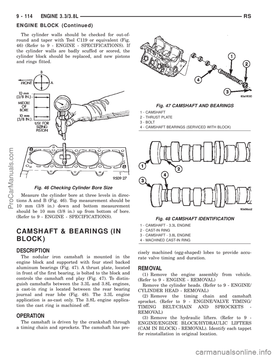
The cylinder walls should be checked for out-of-
round and taper with Tool C119 or equivalent (Fig.
46) (Refer to 9 - ENGINE - SPECIFICATIONS). If
the cylinder walls are badly scuffed or scored, the
cylinder block should be replaced, and new pistons
and rings fitted.
Measure the cylinder bore at three levels in direc-
tions A and B (Fig. 46). Top measurement should be
10 mm (3/8 in.) down and bottom measurement
should be 10 mm (3/8 in.) up from bottom of bore.
(Refer to 9 - ENGINE - SPECIFICATIONS).
CAMSHAFT & BEARINGS (IN
BLOCK)
DESCRIPTION
The nodular iron camshaft is mounted in the
engine block and supported with four steel backed
aluminum bearings (Fig. 47). A thrust plate, located
in front of the first bearing, is bolted to the block and
controls the camshaft end play (Fig. 47). To distin-
guish camshafts between the 3.3L and 3.8L engines,
a cast-in ring is located between the rear bearing
journal and rear lobe (Fig. 48). The 3.3L engine
application is as-cast only. The 3.8L engine applica-
tion the cast ring is machined off.
OPERATION
The camshaft is driven by the crankshaft through
a timing chain and sprockets. The camshaft has pre-cisely machined (egg-shaped) lobes to provide accu-
rate valve timing and duration.
REMOVAL
(1) Remove the engine assembly from vehicle.
(Refer to 9 - ENGINE - REMOVAL)
Remove the cylinder heads. (Refer to 9 - ENGINE/
CYLINDER HEAD - REMOVAL)
(2) Remove the timing chain and camshaft
sprocket. (Refer to 9 - ENGINE/VALVE TIMING/
TIMING BELT/CHAIN AND SPROCKETS -
REMOVAL)
(3) Remove the hydraulic lifters. (Refer to 9 -
ENGINE/ENGINE BLOCK/HYDRAULIC LIFTERS
(CAM IN BLOCK) - REMOVAL). Identify each tappet
for reinstallation in original location.
Fig. 46 Checking Cylinder Bore Size
Fig. 47 CAMSHAFT AND BEARINGS
1 - CAMSHAFT
2 - THRUST PLATE
3 - BOLT
4 - CAMSHAFT BEARINGS (SERVICED WITH BLOCK)
Fig. 48 CAMSHAFT IDENTIFICATION
1 - CAMSHAFT - 3.3L ENGINE
2 - CAST-IN RING
3 - CAMSHAFT - 3.8L ENGINE
4 - MACHINED CAST-IN RING
9 - 114 ENGINE 3.3/3.8LRS
ENGINE BLOCK (Continued)
ProCarManuals.com