Page 4294 of 5127

2005 ACCESSORIES & EQUIPMENT
Instrument Panel, Gages, & Console - Aveo
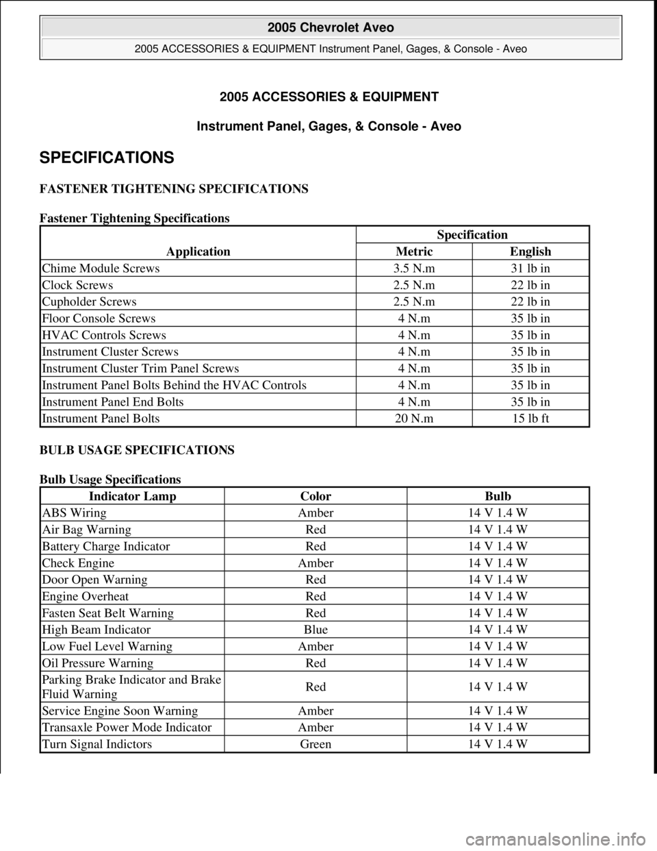
SPECIFICATIONS
FASTENER TIGHTENING SPECIFICATIONS
Fastener Tightening Specifications
BULB USAGE SPECIFICATIONS
Bulb Usage Specifications
Application
Specification
MetricEnglish
Chime Module Screws3.5 N.m31 lb in
Clock Screws2.5 N.m22 lb in
Cupholder Screws2.5 N.m22 lb in
Floor Console Screws4 N.m35 lb in
HVAC Controls Screws4 N.m35 lb in
Instrument Cluster Screws4 N.m35 lb in
Instrument Cluster Trim Panel Screws4 N.m35 lb in
Instrument Panel Bolts Behind the HVAC Controls4 N.m35 lb in
Instrument Panel End Bolts4 N.m35 lb in
Instrument Panel Bolts20 N.m15 lb ft
Indicator LampColorBulb
ABS WiringAmber14 V 1.4 W
Air Bag WarningRed14 V 1.4 W
Battery Charge IndicatorRed14 V 1.4 W
Check EngineAmber14 V 1.4 W
Door Open WarningRed14 V 1.4 W
Engine OverheatRed14 V 1.4 W
Fasten Seat Belt WarningRed14 V 1.4 W
High Beam IndicatorBlue14 V 1.4 W
Low Fuel Level WarningAmber14 V 1.4 W
Oil Pressure WarningRed14 V 1.4 W
Parking Brake Indicator and Brake
Fluid WarningRed14 V 1.4 W
Service Engine Soon WarningAmber14 V 1.4 W
Transaxle Power Mode IndicatorAmber14 V 1.4 W
Turn Signal IndictorsGreen14 V 1.4 W
2005 Chevrolet Aveo
2005 ACCESSORIES & EQUIPMENT Instrument Panel, Gages, & Console - Aveo
2005 Chevrolet Aveo
2005 ACCESSORIES & EQUIPMENT Instrument Panel, Gages, & Console - Aveo
Microsoft
Friday, July 31, 2009 1:07:02 PMPage 1 © 2005 Mitchell Repair Information Company, LLC.
Microsoft
Friday, July 31, 2009 1:07:07 PMPage 1 © 2005 Mitchell Repair Information Company, LLC.
Page 4302 of 5127

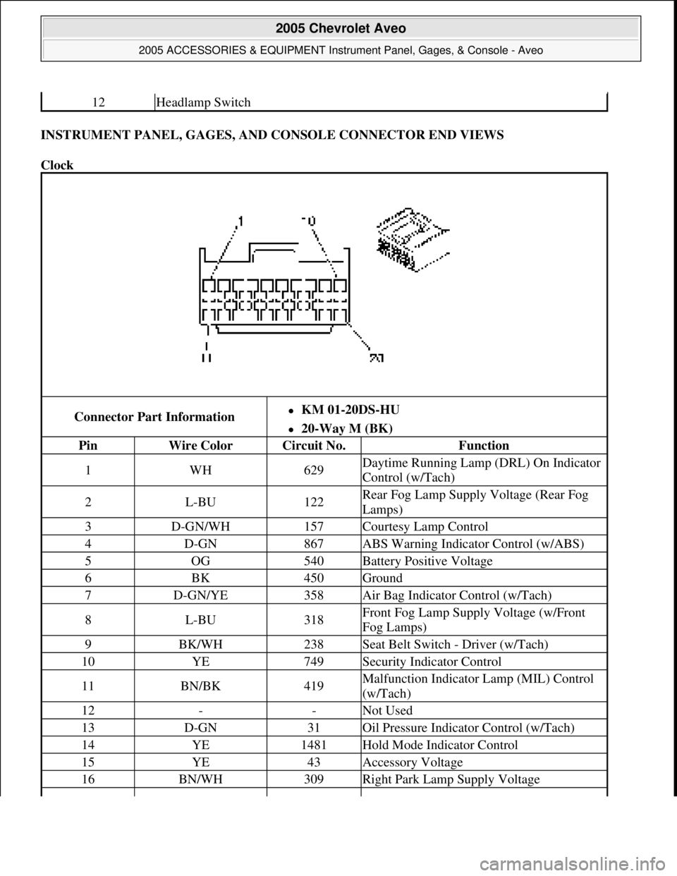
INSTRUMENT PANEL, GAGES, AND CONSOLE CONNECTOR END VIEWS
Clock
12Headlamp Switch
Connector Part InformationKM 01-20DS-HU
20-Way M (BK)
PinWire ColorCircuit No.Function
1WH629Daytime Running Lamp (DRL) On Indicator
Control (w/Tach)
2L-BU122Rear Fog Lamp Supply Voltage (Rear Fog
Lamps)
3D-GN/WH157Courtesy Lamp Control
4D-GN867ABS Warning Indicator Control (w/ABS)
5OG540Battery Positive Voltage
6BK450Ground
7D-GN/YE358Air Bag Indicator Control (w/Tach)
8L-BU318Front Fog Lamp Supply Voltage (w/Front
Fog Lamps)
9BK/WH238Seat Belt Switch - Driver (w/Tach)
10YE749Security Indicator Control
11BN/BK419Malfunction Indicator Lamp (MIL) Control
(w/Tach)
12--Not Used
13D-GN31Oil Pressure Indicator Control (w/Tach)
14YE1481Hold Mode Indicator Control
15YE43Accessory Voltage
16BN/WH309Right Park Lamp Supply Voltage
2005 Chevrolet Aveo
2005 ACCESSORIES & EQUIPMENT Instrument Panel, Gages, & Console - Aveo
Microsoft
Friday, July 31, 2009 1:07:02 PMPage 9 © 2005 Mitchell Repair Information Company, LLC.
Page 4303 of 5127
Ignition Key Alarm Switch
Instrument Cluster
17PK239Ignition 1 Voltage
18--Not Used
19D-BU25Charge Indicator Control/Charge Indicator
Signal (w/Tach)
20YE18Hazard Indicator Control
Connector Part Information
KET MG 610070
2-Way F 090 (2.3 mm) Series (WH)
PinWire ColorCircuit No.Function
1OG340Battery Positive Voltage
2
L-GN80Key In Ignition Switch Signal (w/Remote
Keyless Entry)
L-GN80Key In Ignition Switch Signal (w/Lamp
Driver Module)
2005 Chevrolet Aveo
2005 ACCESSORIES & EQUIPMENT Instrument Panel, Gages, & Console - Aveo
Microsoft
Friday, July 31, 2009 1:07:02 PMPage 10 © 2005 Mitchell Repair Information Company, LLC.
Page 4304 of 5127

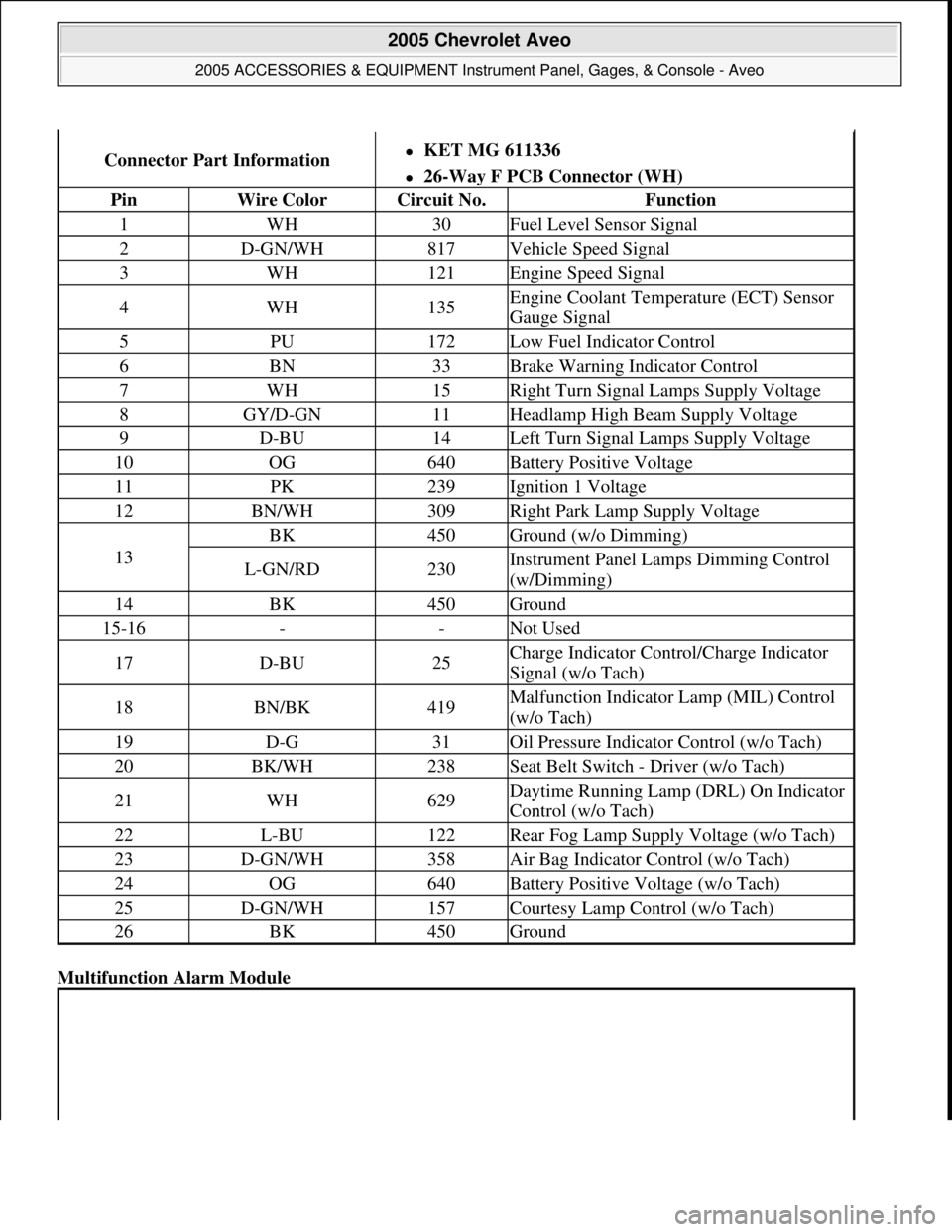
Multifunction Alarm Module
Connector Part InformationKET MG 611336
26-Way F PCB Connector (WH)
PinWire ColorCircuit No.Function
1WH30Fuel Level Sensor Signal
2D-GN/WH817Vehicle Speed Signal
3WH121Engine Speed Signal
4WH135Engine Coolant Temperature (ECT) Sensor
Gauge Signal
5PU172Low Fuel Indicator Control
6BN33Brake Warning Indicator Control
7WH15Right Turn Signal Lamps Supply Voltage
8GY/D-GN11Headlamp High Beam Supply Voltage
9D-BU14Left Turn Signal Lamps Supply Voltage
10OG640Battery Positive Voltage
11PK239Ignition 1 Voltage
12BN/WH309Right Park Lamp Supply Voltage
13
BK450Ground (w/o Dimming)
L-GN/RD230Instrument Panel Lamps Dimming Control
(w/Dimming)
14BK450Ground
15-16--Not Used
17D-BU25Charge Indicator Control/Charge Indicator
Signal (w/o Tach)
18BN/BK419Malfunction Indicator Lamp (MIL) Control
(w/o Tach)
19D-G31Oil Pressure Indicator Control (w/o Tach)
20BK/WH238Seat Belt Switch - Driver (w/o Tach)
21WH629Daytime Running Lamp (DRL) On Indicator
Control (w/o Tach)
22L-BU122Rear Fog Lamp Supply Voltage (w/o Tach)
23D-GN/WH358Air Bag Indicator Control (w/o Tach)
24OG640Battery Positive Voltage (w/o Tach)
25D-GN/WH157Courtesy Lamp Control (w/o Tach)
26BK450Ground
2005 Chevrolet Aveo
2005 ACCESSORIES & EQUIPMENT Instrument Panel, Gages, & Console - Aveo
Microsoft
Friday, July 31, 2009 1:07:02 PMPage 11 © 2005 Mitchell Repair Information Company, LLC.
Page 4324 of 5127

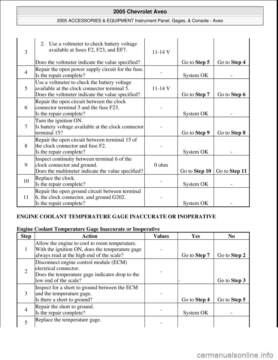
ENGINE COOLANT TEMPERATURE GAGE INACCURATE OR INOPERATIVE
Engine Coolant Temperature Gage Inaccurate or Inoperative
3
2. Use a voltmeter to check battery voltage
available at fuses F2, F23, and EF7.
Does the voltmeter indicate the value specified?
11-14 V
Go to Step 5 Go to Step 4
4Repair the open power supply circuit for the fuse.
Is the repair complete?-System OK-
5
Use a voltmeter to check the battery voltage
available at the clock connector terminal 5.
Does the voltmeter indicate the value specified?
11-14 V
Go to Step 7 Go to Step 6
6
Repair the open circuit between the clock
connector terminal 5 and the fuse F23.
Is the repair complete?
-
System OK-
7
Turn the ignition ON.
Is battery voltage available at the clock connector
terminal 15?
-
Go to Step 9 Go to Step 8
8
Repair the open circuit between terminal 15 of
the clock connector and fuse F2.
Is the repair complete?
-
System OK-
9
Inspect continuity between terminal 6 of the
clock connector and ground.
Does the multimeter indicate the value specified?
0 ohm
Go to Step 10 Go to Step 11
10Replace the clock.
Is the repair complete?-System OK-
11
Repair the open ground circuit between terminal
6, the clock connector, and ground G202.
Is the repair complete?
-
System OK-
StepActionValuesYesNo
1
Allow the engine to cool to room temperature.
With the ignition ON, does the temperature gage
always read at the high end of the scale?
-
Go to Step 7 Go to Step 2
2
Disconnect engine control module (ECM)
electrical connector.
Does the temperature gage indicator drop to the
low end of the scale?
-
-Go to Step 3
3
Inspect for a short to ground between the ECM
and the temperature gage.
Is there a short to ground?
-
Go to Step 4 Go to Step 5
4Repair the short to ground.
Is the repair complete?-System OK-
5Replace the temperature gage. -
2005 Chevrolet Aveo
2005 ACCESSORIES & EQUIPMENT Instrument Panel, Gages, & Console - Aveo
Microsoft
Friday, July 31, 2009 1:07:02 PMPage 31 © 2005 Mitchell Repair Information Company, LLC.
Page 4329 of 5127
Fig. 8: View of Cigar Lighter and Housing
Courtesy of GENERAL MOTORS CORP.
1. Disconnect the negative battery cable.
2. Remove the cigar lighter from the cigar lighter housing.
3. Remove the floor console. Refer to Console Replacement
- Front Floor in Instrument Panel, Gages and
Console.
4. Remove the cigar lighter housing from the instrument panel.
5. Disconnect the cigar lighter electrical connector.
Installation Procedure
CAUTION: Refer to Battery Disconnect Caution in Cautions and Notices.
2005 Chevrolet Aveo
2005 ACCESSORIES & EQUIPMENT Instrument Panel, Gages, & Console - Aveo
Microsoft
Friday, July 31, 2009 1:07:02 PMPage 36 © 2005 Mitchell Repair Information Company, LLC.
Page 4330 of 5127
Fig. 9: View of Cigar Lighter and Housing
Courtesy of GENERAL MOTORS CORP.
1. Connect the cigar lighter electrical connector.
2. Install the cigar lighter housing in the instrument panel.
3. Install the floor console. Refer to Console Replacement
- Front Floor in Instrument Panel, Gages and
Console.
4. Install the cigar lighter in the cigar lighter housing.
5. Connect the negative battery cable.
AUDIO ALARM MODULE REPLACEMENT
Removal Procedure
2005 Chevrolet Aveo
2005 ACCESSORIES & EQUIPMENT Instrument Panel, Gages, & Console - Aveo
Microsoft
Friday, July 31, 2009 1:07:02 PMPage 37 © 2005 Mitchell Repair Information Company, LLC.
Page 4331 of 5127
Fig. 10: View of Chime Module and Screws
Courtesy of GENERAL MOTORS CORP.
1. Disconnect the negative battery cable.
2. Remove the screws and the chime module.
3. Disconnect the electrical connector.
Installation Procedure
CAUTION: Refer to Battery Disconnect Caution in Cautions and Notices.
2005 Chevrolet Aveo
2005 ACCESSORIES & EQUIPMENT Instrument Panel, Gages, & Console - Aveo
Microsoft
Friday, July 31, 2009 1:07:03 PMPage 38 © 2005 Mitchell Repair Information Company, LLC.