Page 4346 of 5127
Fig. 25: View of Screws and Temperature Gage From Cluster Assembly
Courtesy of GENERAL MOTORS CORP.
1. Install the temperature gage to the cluster assembly with the screws.
2. Install the instrument cluster lens and the face plate.
3. Install the instrument cluster. Refer to Instrument Panel Cluster (IPC) Replacement
.
4. Connect the negative battery cable.
INSTRUMENT CLUSTER LAMP REPLACEMENT
Removal Procedure
NOTE: Refer to Fastener Notice in Cautions and Notices.
2005 Chevrolet Aveo
2005 ACCESSORIES & EQUIPMENT Instrument Panel, Gages, & Console - Aveo
Microsoft
Friday, July 31, 2009 1:07:03 PMPage 53 © 2005 Mitchell Repair Information Company, LLC.
Page 4347 of 5127
Fig. 26: View of Bulb From Rear of Cluster
Courtesy of GENERAL MOTORS CORP.
1. Disconnect the negative battery cable.
2. Remove the instrument cluster. Refer to Instrument Panel Cluster (IPC) Replacement
.
3. Remove the bulb from the rear of the cluster.
Installation Procedure
CAUTION: Refer to Battery Disconnect Caution in Cautions and Notices.
2005 Chevrolet Aveo
2005 ACCESSORIES & EQUIPMENT Instrument Panel, Gages, & Console - Aveo
Microsoft
Friday, July 31, 2009 1:07:03 PMPage 54 © 2005 Mitchell Repair Information Company, LLC.
Page 4348 of 5127
Fig. 27: View of Bulb From Rear of Cluster
Courtesy of GENERAL MOTORS CORP.
1. Install the new bulb.
2. Install the instrument cluster. Refer to Instrument Panel Cluster (IPC) Replacement
.
3. Connect the negative battery cable.
ASHTRAY REPLACEMENT
Removal Procedure
NOTE: Refer to Fastener Notice in Cautions and Notices.
2005 Chevrolet Aveo
2005 ACCESSORIES & EQUIPMENT Instrument Panel, Gages, & Console - Aveo
Microsoft
Friday, July 31, 2009 1:07:03 PMPage 55 © 2005 Mitchell Repair Information Company, LLC.
Page 4355 of 5127
Fig. 34: View Of Steering Wheel Column (North America)
Courtesy of GENERAL MOTORS CORP.
1. Disconnect the negative battery cable.
2. Remove the driver's air bag module from the steering wheel, if equipped. Refer to Inflatable Restraint
Steering Wheel Module Replacement in SIR.
3. Remove the steering wheel from the steering column. Refer to Steering Wheel Replacement
in Steering
Wheel and Column.
4. Remove the steering column trim cover. Refer to Steering Column Replacement
in Steering Wheel and
Column.
CAUTION: Refer to Battery Disconnect Caution in Cautions and Notices.
2005 Chevrolet Aveo
2005 ACCESSORIES & EQUIPMENT Instrument Panel, Gages, & Console - Aveo
Microsoft
Friday, July 31, 2009 1:07:03 PMPage 62 © 2005 Mitchell Repair Information Company, LLC.
Page 4363 of 5127
17. Install the steering wheel to the steering column. Refer to Steering Wheel Replacement in Steering
Wheel and Column.
18. Install the driver's air bag module from the steering wheel, if equipped. Refer to Inflatable Restraint
Steering Wheel Module Replacement in SIR.
19. Connect the negative battery cable.
INSTRUMENT PANEL (I/P) ASSEMBLY REPLACEMENT (EUROPEAN AND NON-EUROPEAN)
Removal Procedure
Fig. 42: View Of Steering Wheel Column (European and Non-European)
Courtesy of GENERAL MOTORS CORP.
CAUTION: Refer to Battery Disconnect Caution in Cautions and Notices.
2005 Chevrolet Aveo
2005 ACCESSORIES & EQUIPMENT Instrument Panel, Gages, & Console - Aveo
Microsoft
Friday, July 31, 2009 1:07:03 PMPage 70 © 2005 Mitchell Repair Information Company, LLC.
Page 4364 of 5127

1. Disconnect the negative battery cable.
2. Remove the driver's air bag module from the steering wheel, if equipped. Refer to Inflatable Restraint
Steering Wheel Module Replacement in SIR.
3. Remove the steering wheel from the steering column. Refer to Steering Wheel Replacement
in Steering
Wheel and Column.
4. Remove the steering column trim cover. Refer to Steering Column Replacement
in Steering Wheel and
Column.
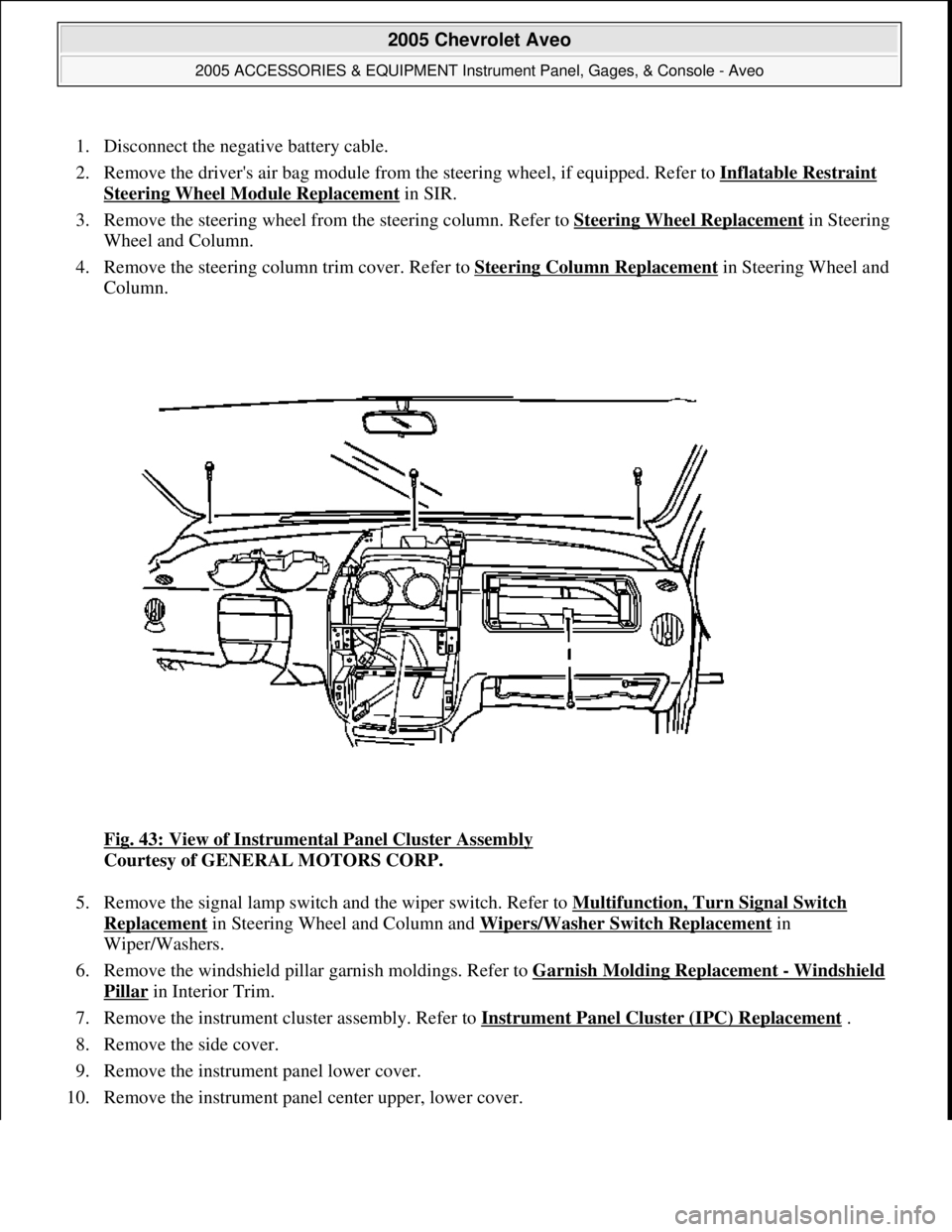
Fig. 43: View of Instrumental Panel Cluster Assembly
Courtesy of GENERAL MOTORS CORP.
5. Remove the signal lamp switch and the wiper switch. Refer to Multifunction, Turn Signal Switch
Replacement in Steering Wheel and Column and Wipers/Washer Switch Replacement in
Wiper/Washers.
6. Remove the windshield pillar garnish moldings. Refer to Garnish Molding Replacement
- Windshield
Pillar in Interior Trim.
7. Remove the instrument cluster assembly. Refer to Instrument Panel Cluster (IPC) Replacement
.
8. Remove the side cover.
9. Remove the instrument panel lower cover.
10. Remove the instrument panel center upper, lower cover.
2005 Chevrolet Aveo
2005 ACCESSORIES & EQUIPMENT Instrument Panel, Gages, & Console - Aveo
Microsoft
Friday, July 31, 2009 1:07:03 PMPage 71 © 2005 Mitchell Repair Information Company, LLC.
Page 4371 of 5127
18. Install the driver's air bag module from the steering wheel, if equipped. Refer to Inflatable Restraint
Steering Wheel Module Replacement in SIR.
19. Connect the negative battery cable.
CLOCK REPLACEMENT - CONSOLE
Removal Procedure
Fig. 50: View of Screws and Clock
Courtesy of GENERAL MOTORS CORP.
1. Disconnect the negative battery cable.
2. Remove the instrument panel center upper cover. Refer to Trim Panel Replacement
- Instrument Panel
(I/P) Center .
3. Remove the screws and the clock.
Installation Procedure
CAUTION: Refer to Battery Disconnect Caution in Cautions and Notices.
2005 Chevrolet Aveo
2005 ACCESSORIES & EQUIPMENT Instrument Panel, Gages, & Console - Aveo
Microsoft
Friday, July 31, 2009 1:07:03 PMPage 78 © 2005 Mitchell Repair Information Company, LLC.
Page 4372 of 5127
Fig. 51: View of Screws and Clock
Courtesy of GENERAL MOTORS CORP.
1. Install the clock with the screws.
Tighten: Tighten the clock screws to 2.5 N.m (23 lb in).
2. Install the instrument panel center upper cover. Refer to Trim Panel Replacement
- Instrument Panel
(I/P) Center .
3. Connect the negative battery cable.
CONSOLE REPLACEMENT - FRONT FLOOR
Removal Procedure
NOTE: Refer to Fastener Notice in Cautions and Notices.
2005 Chevrolet Aveo
2005 ACCESSORIES & EQUIPMENT Instrument Panel, Gages, & Console - Aveo
Microsoft
Friday, July 31, 2009 1:07:03 PMPage 79 © 2005 Mitchell Repair Information Company, LLC.