2002 BMW X5 air intake
[x] Cancel search: air intakePage 5 of 48

M54 ENGINE
MECHANICAL CHANGES
NON RETURN FUEL RAIL SYSTEM
The M54 engine with MS 43.0 control uses the non return fuel rail system introduced on
the M62 TU engine. The system meets running loss compliance without the use of the 3/2-
way solenoid valve currently used on the M52 TU engine.
The regulated fuel supply is controlled by
the fuel pressure regulator integrated in
the fuel filter. The fuel return line is also
located on the filter.
The M54 engine uses an Electronic Controlled
Throttle Valve (EDK) for intake air control. The
idle control valve and turbulence function of the
intake manifold carries over from the M52 TU
engine.
5
M54engMS43/ST036/6/20000
ART-FUELRAIL
Page 14 of 48

14
M54engMS43/ST036/6/2000
MS 43 NEW FUNCTIONS
EDK THROTTLE POSITION FEEDBACK SIGNALS
EDK FEEDBACK SIGNAL MONITORING & EDK FAILSAFE OPERATION:
• The EDK provides two separate signals from two integral potentiometers (Pot 1 and Pot
2) representing the exact position of the throttle plate.
• EDK Pot 1 provides the primary throttle plate position feedback. As a redundant safe-
ty feature, Pot 2 is continuously cross checked with Pot 1 for signal plausibility.
• If plausibility errors are detected between Pot 1 and Pot 2, MS 43.0 will calculate the
inducted engine air mass (from HFM signal) and only utilize the potentiometer signal that
closely matches the detected intake air mass.
- The MS 43.0 uses the air mass signalling as a “virtual potentiometer” (pot 3) for a
comparative source to provide failsafe operation.
- If MS 43.0 cannot calculate a plausible conclusion from the monitored pots (1 or 2
and virtual 3) the EDK motor is switched off and fuel injection cut out is activated
(no failsafe operation possible).
• The EDK is continuously monitored during all phases of engine operation. It is also
briefly activated when KL 15 is initially switched on as a “pre-flight check” to verify it’s
mechanical integrity (no binding, appropriate return spring tension, etc). This is accom-
plished by monitoring both the motor control amperage and the reaction speed of the
EDK feedback potentiometers. If faults are detected the EDK motor is switched off and
fuel injection cut off is activated (no failsafe operation possible). The engine does how-
ever continue to run extremely rough at idle speed.
• When a replacement EDK is installed, the MS 43.0 adapts to the new component
(required amperage draw for motor control, feedback pot tolerance differences, etc).
This occurs immediately after the next cycle of KL 15 for approximately 30 seconds.
During this period of adaptation, the maximum opening of the throttle plate is 25%.
_____________________________________________________________________________
_____________________________________________________________________________
_____________________________________________________________________________
_____________________________________________________________________________
Page 26 of 48

26
M54engMS43/ST036/6/2000
CAMSHAFT SENSOR
-INTAKE AND EXHAUST CAMSHAFTS
The "static" Hall sensors are used so that the camshaft positions are recognized once igni-
tion is “on” - even before the engine is started.
The function of the intake cam sensor:
• Cylinder bank detection for preliminary injection
• Synchronization
• Engine speed sensor (if crankshaft speed sensor fails)
• Position control of the intake cam (VANOS)
The exhaust cam sensor is used for position control of the exhaust cam (VANOS)
If these sensors fail there are no substitute values, the system will operate in the failsafe
mode with no VANOS adjustment. The engine will still operate, but torque reduction will be
noticeable.
NOTE: Use caution on repairs as not to bend the impulse wheels
KL 15 KL 15
MS42.0
SOLENOID
OIL TEMP.
SENSOR TWO POSITION PISTON HOUSING
WITH INTERNAL/EXTERNAL
HELICAL GEAR CUP TWO POSITION PISTON
HOUSING WITH
INTERNAL/EXTERNAL
HELICAL GEAR CUP
ENGINE
OIL SUPPLY VENT VENT
SOLENOID
SENSOR SENSOR
MS42
ECM
EXHAUST
INTAKE
MS42.0
ECM
MS 43.0
MS 43.0
MS 43.0
Page 32 of 48

32
M54engMS43/ST036/6/2000
MS 43 CARRY OVER FUNCTIONS
OUTPUT FUNCTIONS -VANOS CONTROL
With the double VANOS system, the valve timing is changed on both the intake and the
exhaust camshafts.
Double VANOS provides the following benefits:
• Torque increase in the low to mid (1500 - 2000 RPM) range without power loss in the
upper RPM range.
• Less incomplete combustion when idling due to less camshaft overlap (also improves
idle speed characteristics).
• Internal exhaust gas recirculation (EGR) in the part load range (reduces NOx and post-
combustion of residual gasses in the exhaust)
• Rapid catalyst warm up and lower “raw” emissions after cold start.
• Reduction in fuel consumption
Double VANOS consists of the following parts:
• Intake and exhaust camshafts with helical gear insert
• Sprockets with adjustable gears
• VANOS actuators for each camshaft
• 2 three-way solenoid switching valves
• 2 impulse wheels for detecting camshaft position
• 2 camshaft position sensors (Hall effect)
The “initial” timing is set by gear positioning (refer to the Repair Instructions for details) and
the chain tensioner. As with the previous VANOS, the hydraulically controlled actuators
move the helical geared cups to regulate camshaft timing. The angled teeth of the helical
gears cause the pushing
movement of the helical cup to be converted into a rotational
movement. This rotational movement is added to the turning of the camshafts and cause
the camshafts to “advance” or “retard”. The adjustment rate is dependent oil temperature,
oil pressure, and engine RPM.
Page 33 of 48

33
M54engMS43/ST036/6/20000
NOTE: With extremely hot oil temperatures Vanos is deactivated (Power loss). If the oil is
too thick (wrong viscosity) a fault could be set.
When the engine is started, the camshafts are in the “failsafe” position (deactivated). The
intake camshaft is in the RETARDED position - held by oil pressure from the sprung open
solenoid. The exhaust camshaft is in the ADVANCED position - held by a preload spring in
the actuator and oil pressure from the sprung open solenoid.
After 50 RPM (2-5 seconds) from engine start, the ECM is monitoring the exact camshaft
position.
The ECM positions the camshafts based on engine RPM and the throttle position signal.
From that point the camshaft timing will be varied based on intake air and coolant temper-
atures.
The double VANOS system is “fully variable”. When the ECM detects the camshafts are in
the optimum positions, the solenoids are modulated (approximately 100-220 Hz) maintain-
ing oil pressure on both sides of the actuators to hold the camshaft timing.
CAUTION:
The VANOS MUST
be removed and installed exactly as described in the Repair
Instructions!
NOTE: If the VANOS camshaft system goes to the failsafe mode (deactivated) there will be
a noticeable loss of power. This will be like driving with retarded ignition or starting from a
stop in third gear.
KL 15 KL 15
MS42.0
SOLENOID
OIL TEMP.
SENSOR TWO POSITION PISTON HOUSING
WITH INTERNAL/EXTERNAL
HELICAL GEAR CUP TWO POSITION PISTON
HOUSING WITH
INTERNAL/EXTERNAL
HELICAL GEAR CUP
ENGINE
OIL SUPPLY VENT VENT
SOLENOID
SENSOR SENSOR
MS42
ECMEXHAUST
INTAKE
MS42.0
ECM
MS 43.0
MS 43.0
MS 43.0
Page 35 of 48

35
M54engMS43/ST036/6/20000
The dual VANOS in conjunction with the variable intake manifold provides an additional
emission control feature.
Because of the improved combustion, the camshaft timing is adjusted for more overlap.
The increased overlap supports internal exhaust gas recirculation (EGR) which reduces
tailpipe emissions and lowers fuel consumption.
During the part load engine range, the intake camshaft overlap opens the intake valve. This
allows limited exhaust gas reflow the intake manifold.
The “internal” EGR reduces the cylinder temperature thus lowering NOx. This feature pro-
vides EGR without the external hardware as seen on previous systems.
INLET
TURBULENCE
IDLE AIR
CONTROL VALVEMDK
INT. EGR
CATALYST
CLOSE TO
ENGINESECONDARY
AIR
INJECTION
(AIR FILTER)OUTLET-VANOS
(228/80-105)INLET-VANOS
(228/80-120)
Page 41 of 48

41
M54engMS43/ST036/6/20000
RESONANCE/TURBULENCE INTAKE SYSTEM
On the M54, the intake manifold is split into 2 groups of 3 (runners) which increases low
end torque. The intake manifold also has separate (internal) turbulence bores which chan-
nels air from the idle speed actuator directly to one intake valve of each cylinder (matching
bore of 5.5mm in the cylinder head).
Routing the intake air to only one intake valve causes the intake to swirl in the cylinder.
Together with the high flow rate of the intake air due to the small intake cross sections, this
results in a reduction in fluctuations and more stable combustion.
_________________________________________________________________
_________________________________________________________________
_________________________________________________________________
_________________________________________________________________
MDK
HFMHFM
MAGNETIC
VALVE
VACUUM
UNIT
MS42.0MS42.0
RAM TUBE
MAIN MAINIFOLD
RESONANCE TUBE
IDLE AIR CONTROL VALVE
(ZWD)
RESONANCE MANIFOLD
CRANKCASE VENTILATIONTURBULENCE MANIFOLD
TURBULENCE BORE 0:5.5mm
MS 43.0
EDK
Page 42 of 48

42
M54engMS43/ST036/6/2000
RESONANCE SYSTEM
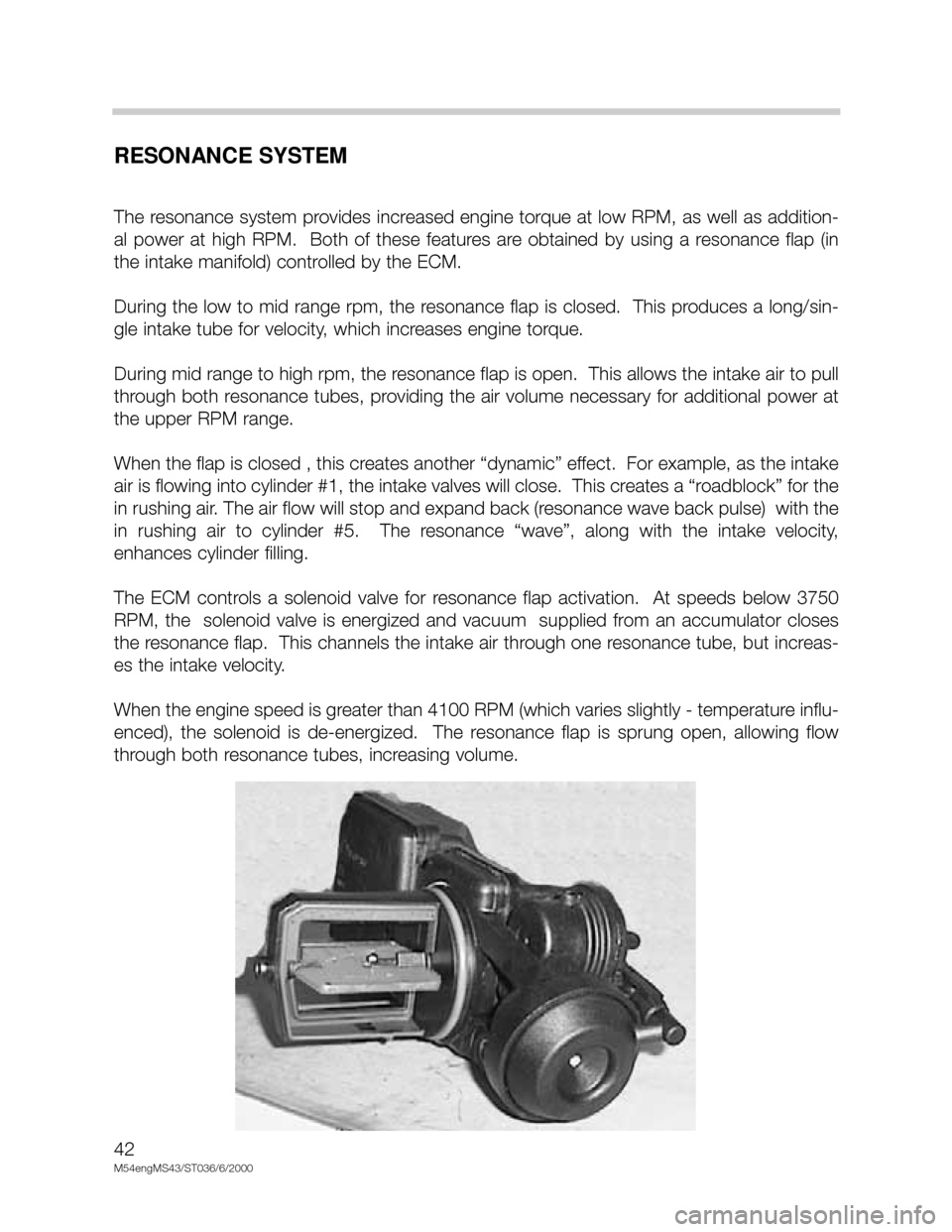
The resonance system provides increased engine torque at low RPM, as well as addition-
al power at high RPM. Both of these features are obtained by using a resonance flap (in
the intake manifold) controlled by the ECM.
During the low to mid range rpm, the resonance flap is closed. This produces a long/sin-
gle intake tube for velocity, which increases engine torque.
During mid range to high rpm, the resonance flap is open. This allows the intake air to pull
through both resonance tubes, providing the air volume necessary for additional power at
the upper RPM range.
When the flap is closed , this creates another “dynamic” effect. For example, as the intake
air is flowing into cylinder #1, the intake valves will close. This creates a “roadblock” for the
in rushing air. The air flow will stop and expand back (resonance wave back pulse) with the
in rushing air to cylinder #5. The resonance “wave”, along with the intake velocity,
enhances cylinder filling.
The ECM controls a solenoid valve for resonance flap activation. At speeds below 3750
RPM, the solenoid valve is energized and vacuum supplied from an accumulator closes
the resonance flap. This channels the intake air through one resonance tube, but increas-
es the intake velocity.
When the engine speed is greater than 4100 RPM (which varies slightly - temperature influ-
enced), the solenoid is de-energized. The resonance flap is sprung open, allowing flow
through both resonance tubes, increasing volume.