Page 65 of 118

PERIODIC MAINTENANCE AND MINOR REPAIR
6-14
6 2. Check the coolant level in the
coolant reservoir.
NOTE:@ The coolant should be between the
minimum and maximum level marks. @3. If the coolant is at or below the
minimum level mark, remove the
coolant reservoir cover by remov-
ing the bolts, open the reservoir
cap, add coolant to the maximum
level mark, close the reservoir
cap, and then install the reservoir
cover and bolts.
EC000080
CAUTION:@ l
If coolant is not available, use
distilled water or soft tap water
instead. Do not use hard water
or salt water since it is harmful
to the engine.
l
If water has been used instead
of coolant, replace it with cool-
ant as soon as possible, other-
wise the engine may not be
sufficiently cooled and the cool-
ing system will not be protected
against frost and corrosion.
l
If water has been added to the
coolant, have a Yamaha dealer
check the antifreeze content of
the coolant as soon as possible,
otherwise the effectiveness of
the coolant will be reduced.
@
EW000067
WARNING
@ Never attempt to remove the radia-
tor cap when the engine is hot. @NOTE:@ The radiator fan is automatically
switched on or off according to the
coolant temperature in the radiator. If
the engine overheats, see page 6-46
for further instructions. @
1. Bolt (´ 2)Left side
Coolant reservoir capacity:
0.44 L
E_5mt.book Page 14 Monday, September 18, 2000 9:08 AM
Page 66 of 118

PERIODIC MAINTENANCE AND MINOR REPAIR
6-15
6
EAU01612
To change the coolant
1. Place the motorcycle on a level
surface and let the engine cool if
necessary.
2. Remove panel C, and cowlings A
and B. (See pages 6-6–6-8 for
panel and cowling removal and in-
stallation procedures.)
3. Place a container under the en-
gine to collect the used coolant.
4. Remove the radiator cap.
EW000067
WARNING
@ Never attempt to remove the radia-
tor cap when the engine is hot. @
5. Remove the water pump drain bolt
to drain the water pump housing.
6. Loosen the clamp screw, and then
disconnect the radiator hose to
drain the radiator.
7. After the coolant is completely
drained, thoroughly flush the cool-
ing system with clean tap water.
8. Connect the radiator hose, and
then tighten the clamp screw.
9. Install the coolant drain bolt, and
then tighten it to the specified
torque.
NOTE:@ Check the washer for damage and re-
place it if necessary. @
1. Radiator capRight side
1. Water pump drain bolt
2. Clamp screwRight side
Tightening torque:
Coolant drain bolt:
12 Nm (1.2 m·kg)
E_5mt.book Page 15 Monday, September 18, 2000 9:08 AM
Page 67 of 118
PERIODIC MAINTENANCE AND MINOR REPAIR
6-16
6 10. Remove the coolant reservoir cov-
er by removing the bolts.11. Remove the coolant reservoir by
removing the bolts.
12. Remove the coolant reservoir cap,
and then turn the reservoir upside-
down to empty it.
13. Install the coolant reservoir by in-
stalling the bolts.
14. Pour the recommended coolant
into the reservoir to the maximum
level mark, and then install the cap
and cover.
15. Pour the recommended coolant
into the radiator until it is full.
1. Bolt (´ 2)Left side
1. Bolt (´ 2)Left side
Antifreeze/water mixture ratio:
1:1
Recommended antifreeze:
High-quality ethylene glycol
antifreeze containing corrosion
inhibitors for aluminum engines
Coolant quantity:
Total amount:
2.15 L
Coolant reservoir capacity:
0.44 L
E_5mt.book Page 16 Monday, September 18, 2000 9:08 AM
Page 68 of 118

PERIODIC MAINTENANCE AND MINOR REPAIR
6-17
6
EC000080
CAUTION:@ l
If coolant is not available, use
distilled water or soft tap water
instead. Do not use hard water
or salt water since it is harmful
to the engine.
l
If water has been used instead
of coolant, replace it with cool-
ant as soon as possible, other-
wise the engine may not be
sufficiently cooled and the cool-
ing system will not be protected
against frost and corrosion.
l
If water has been added to the
coolant, have a Yamaha dealer
check the antifreeze content of
the coolant as soon as possible,
otherwise the effectiveness of
the coolant will be reduced.
@16. Install the radiator cap, start the
engine, let it idle for several min-
utes, and then turn it off.17. Remove the radiator cap to check
the coolant level in the radiator. If
necessary, add sufficient coolant
until it reaches the top of the radia-
tor, and then install the radiator
cap.
18. Start the engine, and then check
the vehicle for coolant leakage. If
coolant is leaking, have a Yamaha
dealer check the cooling system.
19. Install the panel and the cowlings.
EAU03726
Checking the air filter element The air filter element should be
checked at the intervals specified in the
periodic maintenance and lubrication
chart. Check the air filter element more
frequently if you are riding in unusually
wet or dusty areas.
1. Remove the rider seat. (See
page 3-13 for rider seat removal
and installation procedures.)
2. Remove the fuel tank bolts and lift
the fuel tank as shown.1. Bolt (´ 2)
E_5mt.book Page 17 Monday, September 18, 2000 9:08 AM
Page 69 of 118
PERIODIC MAINTENANCE AND MINOR REPAIR
6-18
6 3. Turn the fuel cock lever to “OFF”,
and then disconnect the hoses
and the fuel sender coupler.
NOTE:_ Before removing the hoses, mark them
to ensure that they will be reinstalled in
their correct positions. _
4. Tilt the front of the fuel tank back to
position the tank away from the air
filter case, and then support the
tank as shown.5. Remove the air filter case cover by
removing the screws.
1. Fuel cock
2. Hose (´ 2)
3. Fuel sender coupler
1. Screw (´ 6)
2. Air filter case cover
E_5mt.book Page 18 Monday, September 18, 2000 9:08 AM
Page 70 of 118
PERIODIC MAINTENANCE AND MINOR REPAIR
6-19
66. Pull the air filter element out.
7. Check the condition of the air filter
element and replace it if it is dam-
aged or excessively dusty.8. Insert the element into the air filter
case.
EC000082
CAUTION:_ l
Make sure that the air filter ele-
ment is properly seated in the
air filter case.
l
The engine should never be op-
erated without the air filter ele-
ment installed, otherwise the
piston(s) and/or cylinder(s) may
become excessively worn.
_9. Install the air filter case cover by
installing the screws.
10. Connect the fuel sender coupler
and the hoses, turn the fuel cock
lever to “ON”, place the fuel tank in
the original position, and then in-
stall the bolts.
EW000131
WARNING
_ Make sure that the fuel hoses and
vacuum hose are properly connect-
ed and routed, and not pinched. Re-
place any damaged hoses. _11. Install the rider seat.
1. Air filter elementE_5mt.book Page 19 Monday, September 18, 2000 9:08 AM
Page 71 of 118
PERIODIC MAINTENANCE AND MINOR REPAIR
6-20
6
EAU01335
Air intake duct Check that the screen of the intake
duct is not blocked. Clean the screen if
necessary.
EAU00630
Adjusting the carburetors The carburetors are important parts of
the engine and require very sophisti-
cated adjustment. Therefore, most car-
buretor adjustments should be left to a
Yamaha dealer, who has the neces-
sary professional knowledge and expe-
rience. The adjustment described in
the following section, however, may be
serviced by the owner as part of routine
maintenance.
EC000095
CAUTION:@ The carburetors have been set and
extensively tested at the Yamaha
factory. Changing these settings
without sufficient technical knowl-
edge may result in poor perfor-
mance of or damage to the engine. @
1. Air intake duct
E_5mt.book Page 20 Monday, September 18, 2000 9:08 AM
Page 72 of 118

PERIODIC MAINTENANCE AND MINOR REPAIR
6-21
6
EAU00632
Adjusting the engine idling
speed The engine idling speed must be
checked and, if necessary, adjusted as
follows at the intervals specified in the
periodic maintenance and lubrication
chart.
1. Start the engine and warm it up for
several minutes at 1,000–
2,000 r/min while occasionally rev-
ving it to 4,000–5,000 r/min.NOTE:@ The engine is warm when it quickly re-
sponds to the throttle. @
2. Check the engine idling speed
and, if necessary, adjust it to spec-
ification by turning the throttle stop
screw. To increase the engine
idling speed, turn the screw in di-
rection
a. To decrease the engine
idling speed, turn the screw in
direction
b.NOTE:@ If the specified idling speed cannot be
obtained as described above, have a
Yamaha dealer make the adjustment. @
EAU00635
Adjusting the throttle cable
free play The throttle cable free play should
measure 6–8 mm at the throttle grip.
Periodically check the throttle cable
free play and, if necessary, have a
Yamaha dealer adjust it.
1. Throttle stop screw
Engine idling speed:
1,250–1,350 r/min
a. Throttle cable free play
E_5mt.book Page 21 Monday, September 18, 2000 9:08 AM
 1
1 2
2 3
3 4
4 5
5 6
6 7
7 8
8 9
9 10
10 11
11 12
12 13
13 14
14 15
15 16
16 17
17 18
18 19
19 20
20 21
21 22
22 23
23 24
24 25
25 26
26 27
27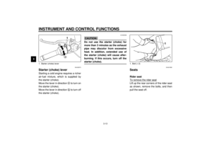 28
28 29
29 30
30 31
31 32
32 33
33 34
34 35
35 36
36 37
37 38
38 39
39 40
40 41
41 42
42 43
43 44
44 45
45 46
46 47
47 48
48 49
49 50
50 51
51 52
52 53
53 54
54 55
55 56
56 57
57 58
58 59
59 60
60 61
61 62
62 63
63 64
64 65
65 66
66 67
67 68
68 69
69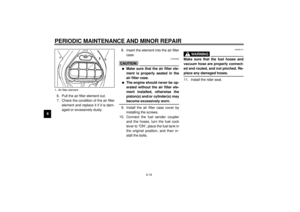 70
70 71
71 72
72 73
73 74
74 75
75 76
76 77
77 78
78 79
79 80
80 81
81 82
82 83
83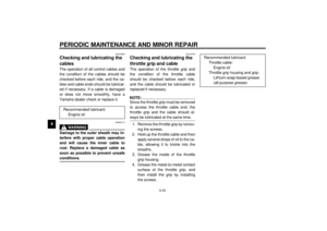 84
84 85
85 86
86 87
87 88
88 89
89 90
90 91
91 92
92 93
93 94
94 95
95 96
96 97
97 98
98 99
99 100
100 101
101 102
102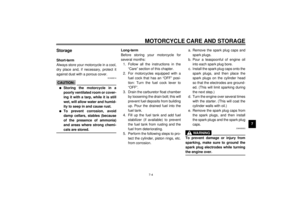 103
103 104
104 105
105 106
106 107
107 108
108 109
109 110
110 111
111 112
112 113
113 114
114 115
115 116
116 117
117


