Page 89 of 118

batte")
PERIODIC MAINTENANCE AND MINOR REPAIR
6-38
6
EC000102
CAUTION:@ l
Always keep the battery
charged. Storing a discharged
battery can cause permanent
battery damage.
l
To charge a sealed-type (MF)
battery, a special (constant-
voltage) battery charger is re-
quired. Using a conventional
battery charger will damage the
battery. If you do not have ac-
cess to a sealed-type (MF) bat-
tery charger, have a Yamaha
dealer charge your battery.
@
EAU01754
Replacing the fuses The fuse box is located under the rider
seat. (See page 3-13 for rider seat re-
moval and installation procedures.)
If a fuse is blown, replace it as follows.
1. Turn the key to “OFF” and turn off
the electrical circuit in question.
2. Remove the blown fuse, and then
install a new fuse of the specified
amperage.1. Headlight fuse
2. Radiator fan fuse
3. Ignition fuse
4. Signaling system fuse
5. Odometer fuse
6. Spare fuse (´ 3)
1. Main fuse
2. Spare main fuseSpecified fuses:
Main fuse: 30 A
Headlight fuse: 20 A
Signaling system fuse: 15 A
Radiator fan fuse: 7.5 A
Ignition fuse: 15 A
Odometer fuse: 7.5 A
E_5mt.book Page 38 Monday, September 18, 2000 9:08 AM
Page 90 of 118

PERIODIC MAINTENANCE AND MINOR REPAIR
6-39
6
EC000103
CAUTION:@ Do not use a fuse of a higher amper-
age rating than recommended to
avoid causing extensive damage to
the electrical system and possibly a
fire. @3. Turn the key to “ON” and turn on
the electrical circuit in question to
check if the device operates.
4. If the fuse immediately blows
again, have a Yamaha dealer
check the electrical system.
EAU01822
Replacing the headlight bulb This motorcycle is equipped with a
quartz bulb headlight. If the headlight
bulb burns out, replace it as follows.
1. Remove panel C. (See page 6-8
for panel removal and installation
procedures.)
2. Disconnect the headlight coupler,
and then remove the headlight
bulb cover.3. Unhook the headlight bulb holder,
and then remove the defective
bulb.
EW000119
WARNING
@ Headlight bulbs get very hot. There-
fore, keep flammable products away
from a lit headlight bulb, and do not
touch the bulb until it has cooled
down. @4. Place a new bulb into position, and
then secure it with the bulb holder.
1. Headlight coupler
2. Headlight bulb cover
1. Headlight bulb holder
E_5mt.book Page 39 Monday, September 18, 2000 9:08 AM
Page 91 of 118

PERIODIC MAINTENANCE AND MINOR REPAIR
6-40
6
EC000104
CAUTION:@ Take care not to damage the follow-
ing parts:l
Headlight bulb
Do not touch the glass part of the
headlight bulb to keep it free from
oil, otherwise the transparency of
the glass, the luminosity of the bulb,
and the bulb life will be adversely af-
fected. Thoroughly clean off any dirt
and fingerprints on the headlight
bulb using a cloth moistened with
alcohol or thinner.
l
Headlight lens
• Do not affix any type of tinted
film or stickers to the head-
light lens.
• Do not use a headlight bulb of
a wattage higher than
specified.
@5. Install the bulb cover, and then
connect the coupler.
6. Install the panel.
7. Have a Yamaha dealer adjust the
headlight beam if necessary.
EAU03730
Tail/brake light This motorcycle is equipped with an
LED type of tail/brake light.
If the tail/brake light does not come on,
have a Yamaha dealer check it.
EAU03497
Replacing a turn signal light
bulb 1. Remove the turn signal light lens
by removing the screw.
2. Remove the defective bulb by
pushing it in and turning it
counterclockwise.
3. Insert a new bulb into the socket,
push it in, and then turn it clock-
wise until it stops.
4. Install the lens by installing the
screw.
ECA00065
CAUTION:@ Do not overtighten the screw, other-
wise the lens may break. @1. Screw
E_5mt.book Page 40 Monday, September 18, 2000 9:08 AM
Page 92 of 118

PERIODIC MAINTENANCE AND MINOR REPAIR
6-41
6
EAU01579
Supporting the motorcycle Since this model is not equipped with a
centerstand, follow these precautions
when removing the front and rear
wheel or performing other mainte-
nance requiring the motorcycle to
stand upright. Check that the motor-
cycle is in a stable and level position
before starting any maintenance. A
strong wooden box can be placed un-
der the engine for added stability.
To service the front wheel
1. Stabilize the rear of the motorcycle
by using a motorcycle stand or, if
an additional motorcycle stand is
not available, by placing a jack un-
der the frame in front of the rear
wheel.
2. Raise the front wheel off the
ground by using a motorcycle
stand.To service the rear wheel
Raise the rear wheel off the ground by
using a motorcycle stand or, if a motor-
cycle stand is not available, by placing
a jack either under each side of the
frame in front of the rear wheel or under
each side of the swingarm.
EAU01617
Front wheel To remove the front wheel
EW000122
WARNING
@ l
It is advisable to have a Yamaha
dealer service the wheel.
l
Securely support the motor-
cycle so that there is no danger
of it falling over.
@1. Loosen the front wheel axle pinch
bolt, then the brake caliper bolts.
2. Loosen the wheel axle with a
19-mm hexagon wrench.1. Wheel axle
2. Front wheel axle pinch bolt
E_5mt.book Page 41 Monday, September 18, 2000 9:08 AM
Page 93 of 118

PERIODIC MAINTENANCE AND MINOR REPAIR
6-42
6 3. Lift the front wheel off the ground
according to the procedure on
page 6-41.
4. Remove the brake hose holders
by removing the bolts.
5. Remove the brake calipers by re-
moving the bolts.
6. Pull the wheel axle out, and then
remove the wheel.
ECA00046
CAUTION:@ Do not apply the brake after the
brake calipers have been removed,
otherwise the brake pads will be
forced shut. @
EAU01638
To install the front wheel
1. Lift the wheel up between the fork
legs.
2. Insert the wheel axle.
3. Lower the front wheel so that it is
on the ground.
4. Push down hard on the handlebar
several times to check for proper
fork operation.
5. Install the brake calipers by install-
ing the bolts.NOTE:@ Make sure that there is enough space
between the brake pads before install-
ing the brake calipers onto the brake
discs. @6. Install the brake hose holders by
installing the bolts.
7. Install the front wheel axle pinch
bolt, and then tighten the wheel
axle, pinch bolt and brake caliper
bolts to the specified torques.
1. Bolt (´ 3)
2. Brake hose holder
3. Front brake caliper
Tightening torques:
Wheel axle:
72 Nm (7.2 m·kg)
Front wheel axle pinch bolt:
20 Nm (2.0 m·kg)
Brake caliper bolt:
40 Nm (4.0 m·kg)
E_5mt.book Page 42 Monday, September 18, 2000 9:08 AM
Page 94 of 118

PERIODIC MAINTENANCE AND MINOR REPAIR
6-43
6
EAU03537
Rear wheel To remove the rear wheel
EW000122
WARNING
_ l
It is advisable to have a Yamaha
dealer service the wheel.
l
Securely support the motor-
cycle so that there is no danger
of it falling over.
_1. Loosen the axle nut and the brake
caliper bolts.
2. Lift the rear wheel off the ground
according to the procedure on
page 6-41.3. Remove the axle nut, and then re-
move the brake caliper by remov-
ing the bolts.
4. Loosen the locknut on each side of
the swingarm.
5. Turn the drive chain adjusting
bolts fully in direction
a.6. Push the wheel forward, and then
remove the drive chain from the
rear sprocket.
NOTE:_ The drive chain does not need to be
disassembled in order to remove and
install the rear wheel. _7. Pull the wheel axle out, and then
remove the wheel.
ECA00048
CAUTION:_ Do not apply the brake after the
wheel has been removed together
with the brake disc, otherwise the
brake pads will be forced shut. _
1. Axle nut
2. Drive chain slack adjusting bolt
3. Locknut
1. Bolt (´ 2)
2. Rear brake caliper
E_5mt.book Page 43 Monday, September 18, 2000 9:08 AM
Page 95 of 118

PERIODIC MAINTENANCE AND MINOR REPAIR
6-44
6
EAU03538
To install the rear wheel
1. Install the wheel by inserting the
wheel axle from the left hand side.
2. Install the drive chain onto the rear
sprocket, and then adjust the drive
chain slack. (See page 6-31 for
drive chain slack adjustment pro-
cedures.)
3. Install the axle nut, and then lower
the rear wheel so that it is on the
ground.
4. Install the brake caliper by install-
ing the bolts.NOTE:_ Make sure that there is enough space
between the brake pads before install-
ing the brake caliper onto the brake
disc. _5. Tighten the axle nut and the brake
caliper bolts to the specified
torques.
EAU03087
Troubleshooting Although Yamaha motorcycles receive
a thorough inspection before shipment
from the factory, trouble may occur dur-
ing operation. Any problem in the fuel,
compression, or ignition systems, for
example, can cause poor starting and
loss of power.
The following troubleshooting charts
represent quick and easy procedures
for checking these vital systems your-
self. However, should your motorcycle
require any repair, take it to a Yamaha
dealer, whose skilled technicians have
the necessary tools, experience, and
know-how to service the motorcycle
properly.
Use only genuine Yamaha replace-
ment parts. Imitation parts may look
like Yamaha parts, but they are often
inferior, have a shorter service life and
can lead to expensive repair bills. Tightening torques:
Axle nut:
150 Nm (15.0 m·kg)
Brake caliper bolt:
40 Nm (4.0 m·kg)
E_5mt.book Page 44 Monday, September 18, 2000 9:08 AM
Page 96 of 118

PERIODIC MAINTENANCE AND MINOR REPAIR
6-45
6
EAU02990
Troubleshooting charts Starting problems or poor engine performance
EW000125
WARNING
@ Keep away open flames and do not smoke while checking or working on the fuel system. @
Check the fuel level in
the fuel tank.1. Fuel
There is enough fuel.
There is no fuel.
Check the compression.
Supply fuel.
The engine does not start.
Check the compression.
Operate the electric starter.2. Compression
There is compression.
There is no compression.
Check the ignition.
Have a Yamaha dealer
check the vehicle.
Remove the spark plugs
and check the electrodes.3. Ignition
Wipe off with a dry cloth and correct the
spark plug gaps, or replace the spark plugs.
Have a Yamaha dealer check the vehicle.
The engine does not start.
Have a Yamaha dealer
check the vehicle.
Operate the electric starter.4. Battery
The engine turns over
quickly.
The engine turns over
slowly.DryWet
The engine does not start.
Check the battery.Open the throttle halfway and operate
the electric starter.
The battery is good.Check the battery lead connections,
and charge the battery if necessary.
E_5mt.book Page 45 Monday, September 18, 2000 9:08 AM
 1
1 2
2 3
3 4
4 5
5 6
6 7
7 8
8 9
9 10
10 11
11 12
12 13
13 14
14 15
15 16
16 17
17 18
18 19
19 20
20 21
21 22
22 23
23 24
24 25
25 26
26 27
27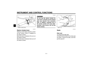 28
28 29
29 30
30 31
31 32
32 33
33 34
34 35
35 36
36 37
37 38
38 39
39 40
40 41
41 42
42 43
43 44
44 45
45 46
46 47
47 48
48 49
49 50
50 51
51 52
52 53
53 54
54 55
55 56
56 57
57 58
58 59
59 60
60 61
61 62
62 63
63 64
64 65
65 66
66 67
67 68
68 69
69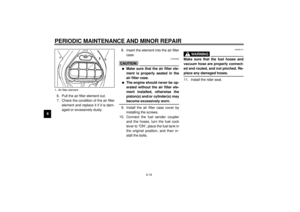 70
70 71
71 72
72 73
73 74
74 75
75 76
76 77
77 78
78 79
79 80
80 81
81 82
82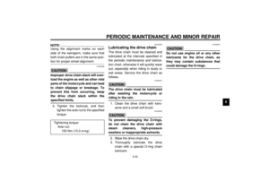 83
83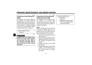 84
84 85
85 86
86 87
87 88
88 89
89 90
90 91
91 92
92 93
93 94
94 95
95 96
96 97
97 98
98 99
99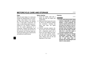 100
100 101
101 102
102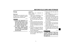 103
103 104
104 105
105 106
106 107
107 108
108 109
109 110
110 111
111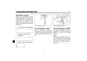 112
112 113
113 114
114 115
115 116
116 117
117