Page 17 of 118

The steering is locked, and the taillights
and auxiliary lights are on, but all other
electrical systems are off. The key can
be removed.
The")
INSTRUMENT AND CONTROL FUNCTIONS
3-2
3
EAU01237
(Parking)
The steering is locked, and the taillights
and auxiliary lights are on, but all other
electrical systems are off. The key can
be removed.
The steering must be locked before the
key can be turned to “ ”.
ECA00043
CAUTION:@ Do not use the parking position for
an extended length of time, other-
wise the battery may discharge. @
EAU03034
Indicator and warning lights
EAU00061
Neutral indicator light “ ”
This indicator light comes on when the
transmission is in the neutral position.
EAU00063
High beam indicator light “ ”
This indicator light comes on when the
high beam of the headlight is switched
on.
EAU00057
Turn signal indicator light “ ”
This indicator light flashes when the
turn signal switch is pushed to the left
or right.
EAU03284
Fuel level warning light “ ”
This warning light comes on when the
fuel level drops below approximately
3.5 L. When this occurs, refuel as soon
as possible.
The electrical circuit of the warning light
can be checked according to the fol-
lowing procedure.
1. Turn the key to “ON”.
2. If the warning light does not come
on, have a Yamaha dealer check
the electrical circuit.NOTE:@ This model is equipped with a self-di-
agnosis device for the fuel level warn-
ing light circuit. (See page 3-23 for an
explanation of the self-diagnosis de-
vice.) @
1. Neutral indicator light “ ”
2. High beam indicator light “ ”
3. Turn signal indicator light “ ”
4. Fuel level warning light “ ”
E_5mt.book Page 2 Monday, September 18, 2000 9:08 AM
Page 18 of 118

INSTRUMENT AND CONTROL FUNCTIONS
3-3
3
EAU03723*
Oil level/coolant temperature warn-
ing light “ ”
This warning light has the following
three functions.l
When the engine oil level is low,
the warning light comes on and
symbol “ ” flashes. If this oc-
curs, stop the engine immediately
and add engine oil to the specified
level.
l
When the coolant temperature is
too high, the warning light comes
on and symbol “ ” flashes. Stop
the motorcycle and allow it to idle
until the coolant temperature goes
down. If the temperature does not
go down, stop the engine. (See
the “Engine overheating” section
on page 6-46 for further instruc-
tions.)
l
When the engine oil level is low
and the coolant temperature is too
high, the warning light flashes and
symbols “ ” and “ ” come on.
To check that the warning light is work-
ing properly:
l
Put the transmission in neutral or
apply the clutch lever.
l
Turn the engine stop switch to
“ ” and the key to “ON”.
l
The warning light will come on and
symbols “ ” and “ ” will ap-
pear in the display.
If the warning light does not come on,
have a Yamaha dealer inspect the
electrical circuit.
EC000118
CAUTION:_ l
Do not operate the motorcycle
until you know that the engine
oil level is sufficient.
l
Do not operate the engine if it is
overheated.
_NOTE:_ Even if the oil is filled to the specified
level, the warning light may flicker
when riding on a slope or during sud-
den acceleration or deceleration, but
this is normal. _
1. Oil level symbol “ ”
2. Oil level/coolant temperature
warning light “ ”
3. Coolant temperature symbol “ ”E_5mt_Functions.fm Page 3 Thursday, September 21, 2000 10:27 AM
Page 19 of 118
INSTRUMENT AND CONTROL FUNCTIONS
3-4
3
CB-19E
Coolant
temperatureDisplay Conditions What to do0–40 °CSymbol and message
“LO” are displayed.OK. Go ahead with riding.
41–117 °CSymbol and temperature
are displayed.OK. Go ahead with riding.
118–140 °CSymbol and temperature
flash.
Warning light comes on.Stop the motorcycle and allow it to
idle until the coolant temperature
goes down.
If the temperature does not go
down, stop the engine. (See the
“Engine overheating” section on
page 6-46 for further instructions.)
Above 140 °CSymbol and message
“HI” flash.
Warning light comes on.Stop the engine and allow it to cool.
(See the “Engine overheating”
section on page 6-46 for further
instructions.)
˚C˚C˚C˚C
E_5mt.book Page 4 Monday, September 18, 2000 9:08 AM
Page 20 of 118

l
an odometer (which shows the t")
INSTRUMENT AND CONTROL FUNCTIONS
3-5
3
EAU03244
Speedometer unit The speedometer unit is equipped with
the following:l
a digital speedometer (which
shows riding speed)
l
an odometer (which shows the to-
tal distance traveled)
l
two tripmeters (which show the
distance traveled since they were
last set to zero)
l
a fuel reserve tripmeter (which
shows the distance traveled on the
fuel reserve)
l
a clock
NOTE:@ For the U.K. only:
To switch the speedometer display be-
tween kilometers and miles, press the
“SELECT” button and “RESET” button
together for at least two seconds. @Odometer and tripmeter modes
Pushing the “SELECT” button switches
the display between the odometer
mode “ODO” and the tripmeter modes
“TRIP 1” and “TRIP 2” in the following
order:
ODO
® TRIP 1
® TRIP 2
® ODO
If the fuel level warning light comes on
(see page 3-2), the odometer display
will automatically change to the fuel re-
serve tripmeter mode “TRIP F” and
start counting the distance traveled
from that point. In that case, pushingthe “SELECT” button switches the dis-
play between the various tripmeter and
odometer modes in the following order:
TRIP F
® TRIP 1
® TRIP 2
® ODO
®
TRIP F
To reset a tripmeter, select it by push-
ing the “SELECT” button, and then
push the “RESET” button for at least
one second. If you do not reset the fuel
reserve tripmeter manually, it will reset
itself automatically and the display will
return to the prior mode after refueling
and traveling 5 km.
Clock mode
To change the display to the clock
mode, push the “SELECT” button for at
least one second.
To change the display back to the prior
mode, push the “SELECT” button.
1. Speedometer
2. Clock/odometer
3. “RESET” button
4. “SELECT” buttonE_5mt.book Page 5 Monday, September 18, 2000 9:08 AM
Page 21 of 118
INSTRUMENT AND CONTROL FUNCTIONS
3-6
3 To set the clock:
1. Push the “SELECT” button and
“RESET” button together for at
least two seconds.
2. When the hour digits start flashing,
push the “RESET” button to set
the hours.
3. Push the “SELECT” button, and
the minute digits will start flashing.
4. Push the “RESET” button to set
the minutes.
5. Push the “SELECT” button and
then release it to start the clock.
EAU00101
Tachometer The electric tachometer allows the rider
to monitor the engine speed and keep it
within the ideal power range.
EC000003
CAUTION:@ Do not operate the engine in the ta-
chometer red zone.
Red zone: 15,500 r/min and above @1. Tachometer
2. Tachometer red zone
E_5mt.book Page 6 Monday, September 18, 2000 9:08 AM
Page 22 of 118

INSTRUMENT AND CONTROL FUNCTIONS
3-7
3
EAU03729
Self-diagnosis device This model is equipped with a self-di-
agnosis device for the following electri-
cal circuits:l
throttle position sensor
l
speed sensor
If any of those circuits are defective,
the tachometer will repeatedly display
the following error code:
CB-11E
Use the table below to identify the
faulty electrical circuit.CB-28EIf the tachometer displays such an er-
ror code, note the circuit-specific num-
ber of r/min, and then have a Yamaha
dealer check the motorcycle.
EC000004
CAUTION:_ When the tachometer displays an
error code, the motorcycle should
be checked as soon as possible in
order to avoid engine damage. _
EAU00118
Handlebar switches
EAU00120
Pass switch “PASS”
Press this switch to flash the headlight.
EAU00121
Dimmer switch
Set this switch to “ ” for the high
beam and to “ ” for the low beam.
0 r/min for
3 seconds
Circuit-specific
number of r/min
for 2.5 seconds
(See the table
below.)
Current
engine
speed for
3 seconds
Specific r/min
Faulty electrical circuit
3,000 r/min
Throttle position sensor
4,000 r/min
Speed sensor
1. Pass switch “PASS”
2. Dimmer switch
3. Turn signal switch
4. Horn switch “ ”
E_5mt.book Page 7 Monday, September 18, 2000 9:08 AM
Page 23 of 118

INSTRUMENT AND CONTROL FUNCTIONS
3-8
3
EAU00127
Turn signal switch
To signal a right-hand turn, push this
switch to “ ”. To signal a left-hand
turn, push this switch to “ ”. When
released, the switch returns to the cen-
ter position. To cancel the turn signal
lights, push the switch in after it has re-
turned to the center position.
EAU00129
Horn switch “ ”
Press this switch to sound the horn.
EAU00138
Engine stop switch
Set this switch to “ ” to stop the en-
gine in case of an emergency, such as
when the motorcycle overturns or
when the throttle cable is stuck.
EAU01238
Light switch
Set this switch to “ ” to turn on the
auxiliary lights, meter lighting and tail-
lights. Set the switch to “ ” to turn on
the headlight also.
EAU00143
Start switch “ ”
Push this switch to crank the engine
with the starter.
EC000005
CAUTION:@ See page 5-1 for starting instruc-
tions prior to starting the engine. @
1. Engine stop switch
2. Light switch
3. Start switch “ ”
E_5mt.book Page 8 Monday, September 18, 2000 9:08 AM
Page 24 of 118
INSTRUMENT AND CONTROL FUNCTIONS
3-9
3
EAU00152
Clutch lever The clutch lever is located at the left
handlebar grip. To disengage the
clutch, pull the lever toward the handle-
bar grip. To engage the clutch, release
the lever. The lever should be pulled
rapidly and released slowly for smooth
clutch operation.
The clutch lever is equipped with a
clutch switch, which is part of the ignition
circuit cut-off system. (See page 3-23
for an explanation of the ignition circuit
cut-off system.)
EAU00157
Shift pedal The shift pedal is located on the left
side of the engine and is used in com-
bination with the clutch lever when
shifting the gears of the 6-speed con-
stant-mesh transmission equipped on
this motorcycle.
EAU00161
Brake lever The brake lever is located at the right
handlebar grip. To apply the front
brake, pull the lever toward the handle-
bar grip.
1. Clutch lever
1. Shift pedal
1. Brake lever
E_5mt.book Page 9 Monday, September 18, 2000 9:08 AM
 1
1 2
2 3
3 4
4 5
5 6
6 7
7 8
8 9
9 10
10 11
11 12
12 13
13 14
14 15
15 16
16 17
17 18
18 19
19 20
20 21
21 22
22 23
23 24
24 25
25 26
26 27
27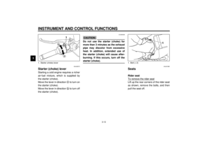 28
28 29
29 30
30 31
31 32
32 33
33 34
34 35
35 36
36 37
37 38
38 39
39 40
40 41
41 42
42 43
43 44
44 45
45 46
46 47
47 48
48 49
49 50
50 51
51 52
52 53
53 54
54 55
55 56
56 57
57 58
58 59
59 60
60 61
61 62
62 63
63 64
64 65
65 66
66 67
67 68
68 69
69 70
70 71
71 72
72 73
73 74
74 75
75 76
76 77
77 78
78 79
79 80
80 81
81 82
82 83
83 84
84 85
85 86
86 87
87 88
88 89
89 90
90 91
91 92
92 93
93 94
94 95
95 96
96 97
97 98
98 99
99 100
100 101
101 102
102 103
103 104
104 105
105 106
106 107
107 108
108 109
109 110
110 111
111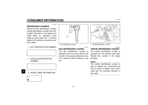 112
112 113
113 114
114 115
115 116
116 117
117

