Page 485 of 626

5 - 29
CHAS
FOURCHE AVANT
TELESKOPGABEL
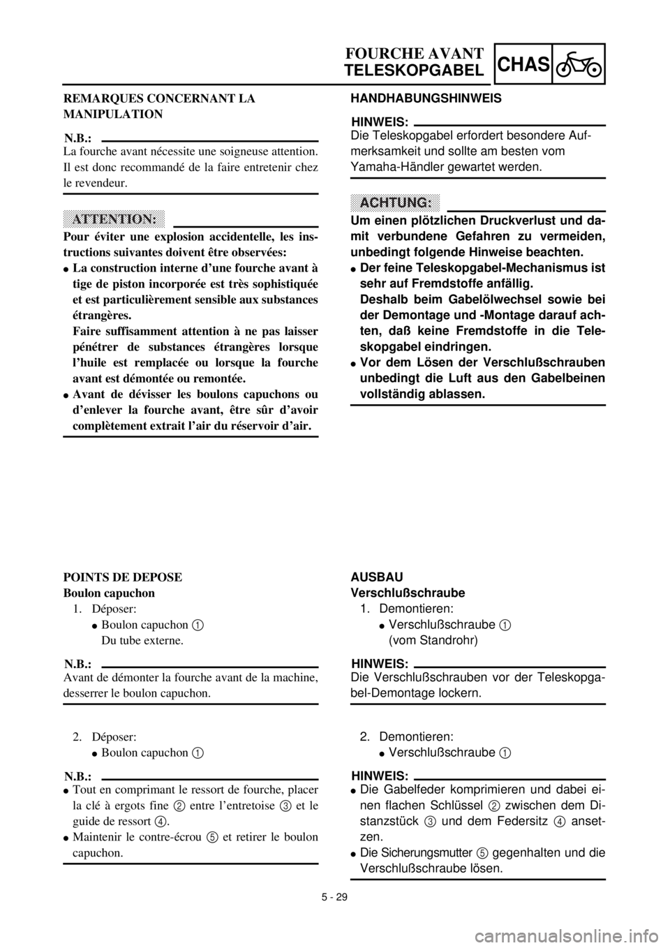
HANDHABUNGSHINWEIS
HINWEIS:
Die Teleskopgabel erfordert besondere Auf-
merksamkeit und sollte am besten vom
Yamaha-Händler gewartet werden.
ACHTUNG:
Um einen plötzlichen Druckverlust und da-
mit verbundene Gefahren zu vermeiden,
unbedingt folgende Hinweise beachten.
lDer feine Teleskopgabel-Mechanismus ist
sehr auf Fremdstoffe anfällig.
Deshalb beim Gabelölwechsel sowie bei
der Demontage und -Montage darauf ach-
ten, daß keine Fremdstoffe in die Tele-
skopgabel eindringen.
lVor dem Lösen der Verschlußschrauben
unbedingt die Luft aus den Gabelbeinen
vollständig ablassen.
AUSBAU
Verschlußschraube
1. Demontieren:
lVerschlußschraube 1
(vom Standrohr)
HINWEIS:
Die Verschlußschrauben vor der Teleskopga-
bel-Demontage lockern.
2. Demontieren:
lVerschlußschraube 1
HINWEIS:
lDie Gabelfeder komprimieren und dabei ei-
nen flachen Schlüssel 2 zwischen dem Di-
stanzstück 3 und dem Federsitz 4 anset-
zen.
lDie Sicherungsmutter 5 gegenhalten und die
Verschlußschraube lösen. REMARQUES CONCERNANT LA
MANIPULATION
N.B.:
La fourche avant nécessite une soigneuse attention.
Il est donc recommandé de la faire entretenir chez
le revendeur.
ATTENTION:
Pour éviter une explosion accidentelle, les ins-
tructions suivantes doivent être observées:
lLa construction interne d’une fourche avant à
tige de piston incorporée est très sophistiquée
et est particulièrement sensible aux substances
étrangères.
Faire suffisamment attention à ne pas laisser
pénétrer de substances étrangères lorsque
l’huile est remplacée ou lorsque la fourche
avant est démontée ou remontée.
lAvant de dévisser les boulons capuchons ou
d’enlever la fourche avant, être sûr d’avoir
complètement extrait l’air du réservoir d’air.
POINTS DE DEPOSE
Boulon capuchon
1. Déposer:
lBoulon capuchon 1
Du tube externe.
N.B.:
Avant de démonter la fourche avant de la machine,
desserrer le boulon capuchon.
2. Déposer:
lBoulon capuchon 1
N.B.:
lTout en comprimant le ressort de fourche, placer
la clé à ergots fine 2 entre l’entretoise 3 et le
guide de ressort 4.
lMaintenir le contre-écrou 5 et retirer le boulon
capuchon.
Page 486 of 626
5 - 30
CHAS
EC553201
Inner tube
1. Remove:
lDust seal 1
lStopper ring 2
Using slotted-head screwdriver.
ACHTUNG:CAUTION:
Take care not to scratch the inner tube.
2. Remove:
lInner tube 1
Oil seal removal steps:
lPush in slowly a the inner tube just before
it bottoms out and then pull it back quickly
b.
lRepeat this step until the inner tube can
be pulled out from the outer tube.
EC553311
Damper rod
1. Remove:
lBase valve 1
lDamper rod 2
NOTE:
Use a damper rod holder 3 to lock the damper
rod.
EC554000
INSPECTION
EC554100
Damper rod
1. Inspect:
lDamper rod 1
Bend/damage ® Replace damper rod.
ACHTUNG:CAUTION:
The front fork with a built-in piston rod has
a very sophisticated internal construction
and is particularly sensitive to foreign
material.
Use enough care not to allow any foreign
material to come in when the oil is replaced
or when the front fork is disassembled and
reassembled.
Damper rod holder:
YM-1423/90890-01423
FRONT FORK
Page 488 of 626
5 - 31
CHAS
EC554200
Base valve
1. Inspect:
lValve assembly 1
Wear/damage ® Replace.
lO-ring 2
Damage ® Replace.
EC554400
Fork spring
1. Measure:
lFork spring free length a
Out of specification ® Replace.
EC554502
Inner tube
1. Inspect:
lInner tube surface a
Score marks ® Repair or replace.
Use #1,000 grit wet sandpaper.
Damaged oil lock piece ® Replace.
lInner tube bends
Out of specification ® Replace.
Use the dial gauge 1.
NOTE:
The bending value is shown by one half of the
dial gauge reading.
WARNING
Do not attempt to straighten a bent inner
tube as this may dangerously weaken the
tube.
EC554600
Outer tube
1. Inspect:
lOuter tube 1
Score marks/wear/damage ® Replace.
Fork spring free length:
Standard Limit
460 mm (18.1 in) 455 mm (17.9 in)
Inner tube bending limit:
0.2 mm (0.008 in)
FRONT FORK
Page 490 of 626
5 - 32
CHAS
EC554700
Cap bolt
1. Inspect:
lCap bolt 1
lO-ring 2
lAir bleed screw 3
Wear/damage ® Replace.
FRONT FORK
EC555000
ASSEMBLY AND INSTALLATION
Front fork assembly
1. Wash the all parts in a clean solvent.
2. Install:
lDamper rod 1
To inner tube 2.
ACHTUNG:CAUTION:
To install the damper rod into the inner
tube, hold the inner tube aslant. If the inner
tube is held vertically, the damper rod may
fall into it, damaging the valve inside.
3. Install:
lCopper washer 1
lO-ring 2
lBase valve 3
To inner tube 4.
4. Tighten:
lBase valve 1
NOTE:
lUse a damper rod holder 2 to lock the
damper rod 3.
lApply the LOCTITE® on the base valve
thread.
Damper rod holder:
YM-1423/90890-01423
New
T R..55 Nm (5.5 m · kg, 40 ft · lb)
Page 492 of 626
5 - 33
CHASFRONT FORK
5. Install:
lSpring guide 1
lLocknut 2
To damper rod 3.
NOTE:
lInstall the spring guide with its cut a facing
upward.
lWith its thread b facing upward, fully finger
tighten the locknut onto the damper rod.
6. Install:
lDust seal 1
lStopper ring 2
lOil seal 3
lPlain washer 4
lSlide metal 5
To inner tube 6.
NOTE:
lApply the fork oil on the inner tube.
lWhen installing the oil seal, use vinyl seat a
with fork oil applied to protect the oil seal lip.
lInstall the oil seal with its manufacture’s
marks or number facing the axle holder side.
New
New
7. Install:
lPiston metal 1
NOTE:
Install the piston metal onto the slot on inner
tube.
New
8. Install:
lOuter tube 1
To inner tube 2.
Page 500 of 626
5 - 37
CHASFRONT FORK
21. Measure:
lDistance a
Out of specification ® Turn into the
locknut.
Distance a:
20 mm (0.79 in) or more
Between damper rod 1 top and
locknut 2 top.
22. Loosen:
lRebound damping adjuster 1
NOTE:
lLoosen the rebound damping adjuster finger
tight.
lRecord the set position of the adjuster (the
amount of turning out the fully turned in posi-
tion).
23. Install
lCushion rubber 1
lWasher 2
lSpacer 3
To cap bolt 4.
NOTE:
Install the cushion rubber with its smaller
dia.end a facing the cap bolt.
24. Install:
lPush rod 1
lFork spring 2
NOTE:
lInstall the fork spring with the damper rod 3
pulled up.
lAfter installing the fork spring, hold the
damper rod end so that it will not go down.
25. Install:
lCap bolt 1
Fully tighten the cap bolt onto the
damper rod by hand.
Page 502 of 626
5 - 38
CHAS
FRONT FORK
26. Tighten:
l
Cap bolt (locknut)
1
NOTE:
l
While compressing the fork spring, set the
thin type spanners
2
between the spacer
3
and spring guide
4
.
l
Hold the locknut
5
and tighten the cap bolt
with specified torque.
27. Install:
l
Cap bolt
1
To outer tube.
NOTE:
Temporarily tighten the cap bolt.
T R..29 Nm (2.9 m · kg, 21 ft · lb)
28. Install:
l
Protector guide
1
Installation
1. Install:
l
Front fork
1
NOTE:
l
Temporarily tighten the pinch bolts (under
bracket).
l
Do not tighten the pinch bolts (handle crown)
yet.
2. Tighten:
l
Cap bolt
1
3. Adjust:
l
Front fork top end
a
Front fork top end (standard) a:
Zero mm (Zero in)
T R..30 Nm (3.0 m · kg, 22 ft · lb)
Page 509 of 626

5 - 41
CHAS
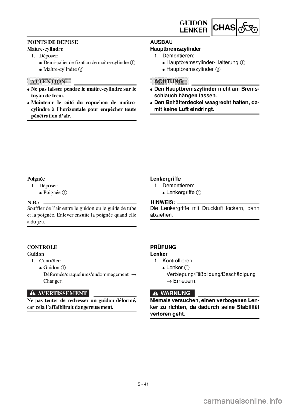
AUSBAU
Hauptbremszylinder
1. Demontieren:
l
Hauptbremszylinder-Halterung
1
l
Hauptbremszylinder
2
ACHTUNG:
l
Den Hauptbremszylinder nicht am Brems-
schlauch hängen lassen.
l
Den Behälterdeckel waagrecht halten, da-
mit keine Luft eindringt.
Lenkergriffe
1. Demontieren:
l
Lenkergriffe
1
HINWEIS:
Die Lenkergriffe mit Druckluft lockern, dann
abziehen.
PRÜFUNG
Lenker
1. Kontrollieren:
l
Lenker
1
Verbiegung/Rißbildung/Beschädigung
®
Erneuern.
WARNUNG
Niemals versuchen, einen verbogenen Len-
ker zu richten, da dadurch seine Stabilität
verloren geht.
GUIDON
LENKER
POINTS DE DEPOSE
Maître-cylindre
1. Déposer:
l
Demi-palier de fixation de maître-cylindre
1
l
Maître-cylindre
2
ATTENTION:
l
Ne pas laisser pendre le maître-cylindre sur le
tuyau de frein.
l
Maintenir le côté du capuchon de maître-
cylindre à l’horizontale pour empêcher toute
pénétration d’air.
Poignée
1. Déposer:
l
Poignée
1
N.B.:
Souffler de l’air entre le guidon ou le guide de tube
et la poignée. Enlever ensuite la poignée quand elle
a du jeu.
CONTROLE
Guidon
1. Contrôler:
l
Guidon
1
Déformée/craquelures/endommagement
®
Changer.
AVERTISSEMENT
Ne pas tenter de redresser un guidon déformé,
car cela l’affaiblirait dangereusement.