Page 15 of 132

3
INSTRUMENT AND CONTROL FUNCTIONS
Main switch/steering lock ..................................... 3-1
Indicator and warning lights ................................ 3-3
Speedometer unit ................................................ 3-5
Cruise control system ........................................... 3-6
Fuel gauge ........................................................... 3-8
Anti-theft alarm (optional) .................................... 3-8
Handlebar switches ............................................. 3-9
Clutch lever ........................................................ 3-10
Shift pedal .......................................................... 3-10
Brake lever ......................................................... 3-11
Brake pedal ........................................................ 3-11
Fuel tank cap ..................................................... 3-11
Fuel .................................................................... 3-12Fuel tank breather hose .................................... 3-13
Fuel cock ........................................................... 3-13
Starter (choke) knob ......................................... 3-14
Locking the steering with a padlock .................. 3-14
Rider seat .......................................................... 3-15
Helmet holders .................................................. 3-15
Side cases and travel trunk ............................... 3-16
Adjusting the front fork ...................................... 3-19
Adjusting the shock absorber assembly ............ 3-20
Sidestand .......................................................... 3-21
Ignition circuit cut-off system ............................. 3-22
Auxiliary DC jack and terminals ........................ 3-24
E_5jc.book Page 1 Monday, January 22, 2001 12:12 PM
Page 16 of 132

3-1
3
EAU00027
3-INSTRUMENT AND CONTROL FUNCTIONS
EAU00029
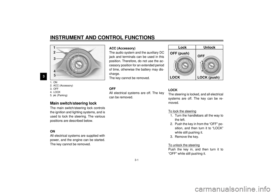
Main switch/steering lock The main switch/steering lock controls
the ignition and lighting systems, and is
used to lock the steering. The various
positions are described below.
EAU00036
ON
All electrical systems are supplied with
power, and the engine can be started.
The key cannot be removed.
EAU01842
ACC (Accessory)
The audio system and the auxiliary DC
jack and terminals can be used in this
position. Therefore, do not use the ac-
cessory position for an extended period
of time, otherwise the battery may dis-
charge.
The key cannot be removed.
EAU00038
OFF
All electrical systems are off. The key
can be removed.
EAU00040
LOCK
The steering is locked, and all electrical
systems are off. The key can be re-
moved.
To lock the steering1. Turn the handlebars all the way to
the left.
2. Push the key in from the “OFF” po-
sition, and then turn it to “LOCK”
while still pushing it.
3. Remove the key.
To unlock the steeringPush the key in, and then turn it to
“OFF” while still pushing it.
1. ON
2. ACC (Accessory)
3. OFF
4. LOCK
5. (Parking)E_5jc.book Page 1 Monday, January 22, 2001 12:12 PM
Page 17 of 132
INSTRUMENT AND CONTROL FUNCTIONS
3-2
3
EW000016
WARNING
@ Never turn the key to “OFF” or
“LOCK” while the motorcycle is
moving, otherwise the electrical
systems will be switched off, which
may result in loss of control or an
accident. Make sure that the motor-
cycle is stopped before turning the
key to “OFF” or “LOCK”. @1. Push.
2. Turn.
EAU01861
(Parking)
The steering is locked, and the taillight,
license light and auxiliary light are on,
but all other electrical systems are off.
The key can be removed.
The steering must be locked before the
key can be turned to “ ”.
ECA00043
CAUTION:_ Do not use the parking position for
an extended length of time, other-
wise the battery may discharge. _
E_5jc.book Page 2 Monday, January 22, 2001 12:12 PM
Page 24 of 132

INSTRUMENT AND CONTROL FUNCTIONS
3-9
3
EAU00118
Handlebar switches
EAU00119
1. Pass switch “ ”
Press this switch to flash the headlight.
EAU03888
2. Dimmer switch “ / ”
Set this switch to “ ” for the high
beam and to “ ” for the low beam.
EAU03889
3. Turn signal switch “ / ”
To signal a right-hand turn, push this
switch to “ ”. To signal a left-hand
turn, push this switch to “ ”. When
released, the switch returns to the cen-
ter position. To cancel the turn signal
lights, push the switch in after it has re-
turned to the center position.
EAU00129
4. Horn switch “ ”
Press this switch to sound the horn.
EAU03890
5. Engine stop switch “ / ”
Set this switch to “ ” before starting
the engine. Set this switch to “ ” to
stop the engine in case of an emergen-
cy, such as when the motorcycle over-
turns or when the throttle cable is
stuck.
EAU03966
6. Light switch “ / / ”
Set this switch to “ ” to turn on the
auxiliary light, meter lighting, taillight
and license plate light. Set the switch to
“ ” to turn on the headlight also. Set
the switch to “ ” to turn off all the
lights.
E_5jc.book Page 9 Monday, January 22, 2001 12:12 PM
Page 39 of 132
INSTRUMENT AND CONTROL FUNCTIONS
3-24
3
EAU01788
Auxiliary DC jack and
terminals 12-V accessories connected to the
auxiliary DC jack at the front and auxil-
iary DC terminals under the rider seat
can be used when the key is in the
“ACC” or “ON” position.
ECA00044
CAUTION:@ The accessories connected to the
auxiliary DC jack and terminals
should not be used with the engine
turned off, and their combined load
must never exceed 5 A or 60 W, oth-
erwise the battery may discharge. @
EWA00017
WARNING
@ To prevent electrical shock or short-
circuiting, make sure that the caps
are installed when the auxiliary DC
jack and terminals are not being
used. @
1. Auxiliary DC jack
1. Auxiliary DC terminal
E_5jc.book Page 24 Monday, January 22, 2001 12:12 PM
Page 41 of 132
AUDIO SYSTEM
4
Location of parts ............................................................................... 4-1
Headsets (optional) ........................................................................... 4-2
Control unit ........................................................................................ 4-3
Making basic settings ........................................................................ 4-5
Making mode settings ....................................................................... 4-5
Cassette deck operation .................................................................... 4-9
Radio operation ............................................................................... 4-12
Optional CD changer operation ....................................................... 4-17
Auxiliary audio source operation ..................................................... 4-18
E_5jc.book Page 1 Monday, January 22, 2001 12:12 PM
Page 42 of 132
4-1
4
EAU03968*
4-AUDIO SYSTEMLocation of parts 1. Audio system control unit
2. Front speaker (´ 2)
3. Rider headset jack
4. Cassette deck lid
5. Main switch/steering lock6. Eject (“ ”) button
7. Cassette deck compartment
8. Auxiliary audio input jack
1. Rear speaker (´ 2)
2. Passenger volume control knob
3. Passenger headset jack
E_5jc.book Page 1 Monday, January 22, 2001 12:12 PM
Page 44 of 132

AUDIO SYSTEM
4-3
4
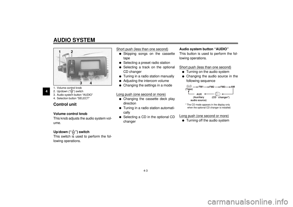
Control unit Volume control knob
This knob adjusts the audio system vol-
ume.
Up/down (“ ”) switch
This switch is used to perform the fol-
lowing operations.Short push (less than one second)
l
Skipping songs on the cassette
tape
l
Selecting a preset radio station
l
Selecting a track on the optional
CD changer
l
Tuning in a radio station manually
l
Adjusting the intercom volume
l
Changing the settings in a mode
Long push (one second or more)
l
Changing the cassette deck play
direction
l
Tuning in a radio station automati-
cally
l
Selecting a CD in the optional CD
changerAudio system button “AUDIO”
This button is used to perform the fol-
lowing operations.
Short push (less than one second)
l
Turning on the audio system
l
Changing the audio source in the
following sequence
Long push (one second or more)
l
Turning off the audio system
1. Volume control knob
2. Up/down (“ ”) switch
3. Audio system button “AUDIO”
4. Selection button “SELECT”
(Tape)FM1
FM2
FM3AM
AUX
(CD changer
*)
(Auxiliary
audio source)
* The CD mode appears in the display only
when the optional CD changer is installed.
E_5jc.book Page 3 Monday, January 22, 2001 12:12 PM