2001 YAMAHA XVZ1300TF AUX
[x] Cancel search: AUXPage 54 of 132

AUDIO SYSTEM
4-13
4
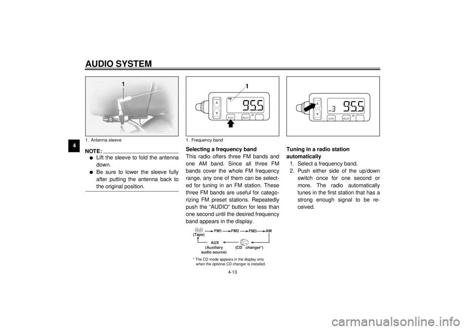
NOTE:_ l
Lift the sleeve to fold the antenna
down.
l
Be sure to lower the sleeve fully
after putting the antenna back to
the original position.
_
Selecting a frequency band
This radio offers three FM bands and
one AM band. Since all three FM
bands cover the whole FM frequency
range, any one of them can be select-
ed for tuning in an FM station. These
three FM bands are useful for catego-
rizing FM preset stations. Repeatedly
push the “AUDIO” button for less than
one second until the desired frequency
band appears in the display.Tuning in a radio station
automatically
1. Select a frequency band.
2. Push either side of the up/down
switch once for one second or
more. The radio automatically
tunes in the first station that has a
strong enough signal to be re-
ceived.
1. Antenna sleeve
1. Frequency band
(Tape)FM1
FM2
FM3AM
AUX
(CD changer
*)
(Auxiliary
audio source)
* The CD mode appears in the display only
when the optional CD changer is installed.
E_5jc.book Page 13 Monday, January 22, 2001 12:12 PM
Page 59 of 132

AUDIO SYSTEM
4-18
4
Auxiliary audio source
operation Auxiliary audio equipment can be con-
nected to, and played through, the au-
dio system.
1. Insert the output plug of the auxil-
iary equipment into the jack locat-
ed at the right of the cassette
deck.2. Repeatedly push the “AUDIO” but-
ton for less than one second until
“AUX” appears in the display. The
auxiliary equipment can now be
played through the audio system.1. Auxiliary audio input jack
E_5jc.book Page 18 Monday, January 22, 2001 12:12 PM
Page 106 of 132

PERIODIC MAINTENANCE AND MINOR REPAIR
7-33
7To charge the battery
Have a Yamaha dealer charge the bat-
tery as soon as possible if it seems to
have discharged. Keep in mind that the
battery tends to discharge more quickly
if the motorcycle is equipped with op-
tional electrical accessories.
To store the battery
1. If the motorcycle will not be used
for more than one month, remove
the battery, fully charge it, and
then place it in a cool, dry place.
2. If the battery will be stored for
more than two months, check it at
least once a month and fully
charge it if necessary.
3. Fully charge the battery before in-
stallation.
4. After installation, make sure that
the battery leads are properly con-
nected to the battery terminals.
EC000102
CAUTION:@ l
Always keep the battery
charged. Storing a discharged
battery can cause permanent
battery damage.
l
To charge a sealed-type (MF)
battery, a special (constant-
voltage) battery charger is re-
quired. Using a conventional
battery charger will damage the
battery. If you do not have ac-
cess to a sealed-type (MF) bat-
tery charger, have a Yamaha
dealer charge your battery.
@
EAU01801*
Replacing the fuses The main fuse box is located behind
panel C. (See page 7-10 for panel re-
moval and installation procedures.)
Fuse box 1 is located behind cowling A.
(See page 7-6 for cowling removal and
installation procedures.)1. Cruise control fuse
2. Carburetor heater fuse
3. Auxiliary DC terminal fuse
4. Auxiliary DC jack fuse
5. Audio system fuse
6. Spare fuse (´ 2)
E_5jc.book Page 33 Monday, January 22, 2001 12:12 PM
Page 107 of 132

PERIODIC MAINTENANCE AND MINOR REPAIR
7-34
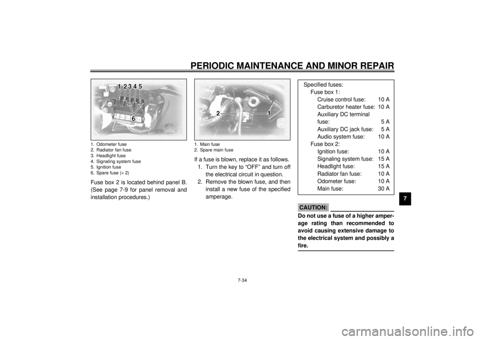
7 Fuse box 2 is located behind panel B.
(See page 7-9 for panel removal and
installation procedures.)If a fuse is blown, replace it as follows.
1. Turn the key to “OFF” and turn off
the electrical circuit in question.
2. Remove the blown fuse, and then
install a new fuse of the specified
amperage.
EC000103
CAUTION:@ Do not use a fuse of a higher amper-
age rating than recommended to
avoid causing extensive damage to
the electrical system and possibly a
fire. @
1. Odometer fuse
2. Radiator fan fuse
3. Headlight fuse
4. Signaling system fuse
5. Ignition fuse
6. Spare fuse (´ 2)
1. Main fuse
2. Spare main fuse
Specified fuses:
Fuse box 1:
Cruise control fuse: 10 A
Carburetor heater fuse: 10 A
Auxiliary DC terminal
fuse: 5 A
Auxiliary DC jack fuse: 5 A
Audio system fuse: 10 A
Fuse box 2:
Ignition fuse: 10 A
Signaling system fuse: 15 A
Headlight fuse: 15 A
Radiator fan fuse: 10 A
Odometer fuse: 10 A
Main fuse: 30 A
E_5jc.book Page 34 Monday, January 22, 2001 12:12 PM
Page 123 of 132

SPECIFICATIONS
9-4
9
Bulb voltage, wattage ´ quantity
Headlight 12 V, 60/55 W ´ 1
Tail/brake light 12 V, 5/21 W ´ 1
Turn signal light 12 V, 21 W ´ 4
Auxiliary light 12 V, 4 W ´ 1
License light 12 V, 5 W ´ 2
Neutral indicator light 12 V, 1.7 W ´ 1
High beam indicator light 12 V, 1.7 W ´ 1
Oil level warning light 12 V, 1.7 W ´ 1
Turn signal indicator light 12 V, 1.7 W ´ 2
Fuel level warning light 14 V, 3 W ´ 1
Coolant temperature warning
light 12 V, 1.7 W ´ 1
Engine trouble warning light 12 V, 1.7 W ´ 1
Overdrive indicator light 12 V, 1.7 W ´ 1
Cruise control “SET” indicator
light 12 V, 1.7 W ´ 1
Cruise control “RES” indicator
light 12 V, 1.7 W ´ 1
Cruise control “ON” indicator
light 12 V, 1.7 W ´ 1Audio system amplifier
Output power
Speaker 14 W ´ 4
Headset 1 W ´ 2
Auto-volume range 5 steps
Output impedance
Speaker 4 W
Headset 8–16 W
Fuses
Main fuse 30 A
Headlight fuse 15 A
Signaling system fuse 15 A
Ignition fuse 10 A
Radiator fan fuse 10 A
Odometer fuse 10 A
Cruise control fuse 10 A
Carburetor heater fuse 10 A
Audio system fuse 10 A
Auxiliary DC jack fuse 5 A
Auxiliary DC terminal fuse 5 A
E_5jc.book Page 4 Monday, January 22, 2001 12:12 PM
Page 128 of 132

11-INDEXAAir filter elements, cleaning .................... 7-17
Anti-theft alarm ........................................3-8
Audio settings (basic) ...............................4-5
Audio settings (modes) ............................4-5
Audio system parts, location of................4-1
Auxiliary audio source ............................ 4-18
Auxiliary DC jack and terminals.............. 3-24BBattery ................................................... 7-32
Brake and clutch fluid levels,
checking .............................................. 7-28
Brake and clutch fluids, changing........... 7-29
Brake and clutch levers, checking and
lubricating ............................................ 7-30
Brake and shift pedals, checking and
lubricating ............................................ 7-29
Brake lever............................................. 3-11
Brake lever free play, adjusting .............. 7-25
Brake light switch (rear), adjusting ......... 7-26
Brake pads, checking............................. 7-27
Brake pedal............................................ 3-11
Brake pedal position, adjusting .............. 7-26CCarburetors, adjusting............................ 7-19
Care.........................................................8-1
Cassette deck operation ..........................4-9
CD changer operation ............................ 4-17
Clutch lever ............................................ 3-10
Clutch lever free play ............................. 7-25
Conversion table ......................................9-5
Coolant level, checking .......................... 7-15
Coolant temperature warning light ........... 3-4
Cowlings and panels, removing and
installing................................................ 7-6
Cruise control indicator lights ................... 3-4
Cruise control switches .......................... 3-10
Cruise control system .............................. 3-6DDimmer switch ......................................... 3-9EEngine break-in ....................................... 6-5
Engine oil and oil filter cartridge ............. 7-12
Engine stop switch................................... 3-9
Engine trouble warning light .................... 3-3FFinal gear oil .......................................... 7-15
Front fork, adjusting ............................... 3-19
Front fork, checking ............................... 7-31
Fuel ....................................................... 3-12
Fuel cock ............................................... 3-13
Fuel consumption, tips for reducing ......... 6-4
Fuel gauge .............................................. 3-8
Fuel level warning light ............................ 3-4
Fuel tank breather hose ......................... 3-13
Fuel tank cap ......................................... 3-11
Fuses, replacing .................................... 7-33HHandlebar switches ................................. 3-9
Headlight bulb, replacing ....................... 7-35
Headsets ................................................. 4-2
Helmet holders ...................................... 3-15
High beam indicator light ......................... 3-3
Horn switch ..............................................3-9IIdentification numbers ............................10-1
Idling speed, adjusting ...........................7-20
Ignition circuit cut-off system ..................3-22
Indicator and warning lights......................3-3KKey identification number .......................10-1LLicense plate light bulb, replacing...........7-37
Light switch ..............................................3-9MMain switch/steering lock .........................3-1
Model label ............................................10-2NNeutral indicator light ...............................3-4OOil level warning light ...............................3-3
Overdrive indicator light............................3-3PParking.....................................................6-6
Part locations ...........................................2-1
Pass switch ..............................................3-9
Periodic maintenance and lubrication
chart ......................................................7-3
Pre-operation check list ............................5-1RRadio operation......................................4-12
Rider seat ..............................................3-15
E_5jc.book Page 1 Monday, January 22, 2001 12:12 PM