Page 22 of 88

INSTRUMENT AND CONTROL FUNCTIONS
3-10
3
EAU00300
Adjusting the shock absorber
assemblies Each shock absorber assembly is
equipped with a spring preload adjust-
ing ring.
EC000015
CAUTION:_ Never attempt to turn an adjusting
mechanism beyond the maximum
or minimum settings. _
EW000040
WARNING
_ Always adjust both shock absorber
assemblies equally, otherwise poor
handling and loss of stability may
result. _
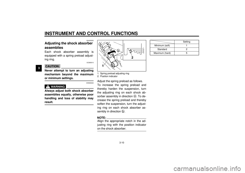
Adjust the spring preload as follows.
To increase the spring preload and
thereby harden the suspension, turn
the adjusting ring on each shock ab-
sorber assembly in direction
a. To de-
crease the spring preload and thereby
soften the suspension, turn the adjust-
ing ring on each shock absorber as-
sembly in direction
b.NOTE:_ Align the appropriate notch in the ad-
justing ring with the position indicator
on the shock absorber. _
CI-10E
1. Spring preload adjusting ring
2. Position indicator
Setting
Minimum (soft) 1
Standard 2
Maximum (hard) 5
E_5kr.book Page 10 Tuesday, September 12, 2000 4:46 PM
Page 49 of 88

PERIODIC MAINTENANCE AND MINOR REPAIR
6-17
6
EWA00012
WARNING
_ Because loading has an enormous
impact on the handling, braking,
performance and safety characteris-
tics of your motorcycle, you should
keep the following precautions in
mind. l
NEVER OVERLOAD THE
MOTORCYCLE! Operation of an
overloaded motorcycle may re-
sult in tire damage, loss of con-
trol, or severe injury. Make sure
that the total weight of rider,
passenger, cargo, and accesso-
ries does not exceed the speci-
fied maximum load for the
vehicle.
l
Do not carry along loosely
packed items, which can shift
during a ride.
l
Securely pack the heaviest
items close to the center of the
motorcycle and distribute the
weight evenly on both sides.
l
Adjust the suspension and tire
air pressure with regard to the
load.
l
Check the tire condition and air
pressure before each ride.
_
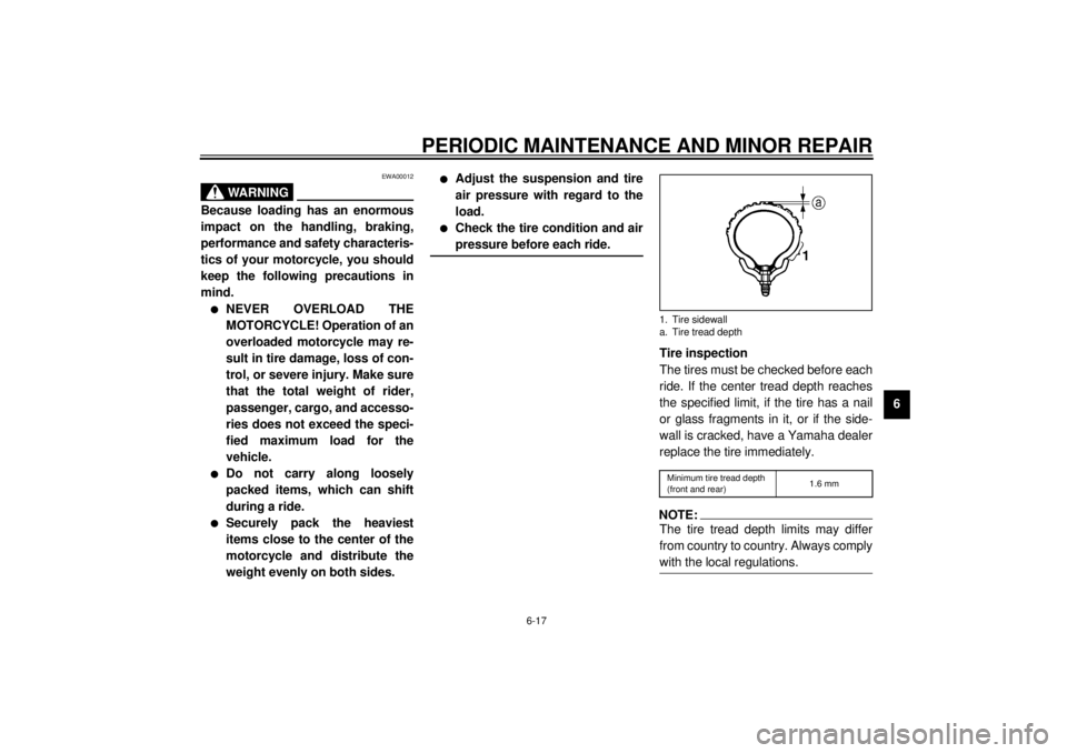
Tire inspection
The tires must be checked before each
ride. If the center tread depth reaches
the specified limit, if the tire has a nail
or glass fragments in it, or if the side-
wall is cracked, have a Yamaha dealer
replace the tire immediately.CE-08ENOTE:_ The tire tread depth limits may differ
from country to country. Always comply
with the local regulations. _1. Tire sidewall
a. Tire tread depthMinimum tire tread depth
(front and rear)1.6 mm
E_5kr.book Page 17 Tuesday, September 12, 2000 4:46 PM
Page 81 of 88
SPECIFICATIONS
8-3
8
Maximum load* 180 kg
Tire air pressure (measured
on cold tires)
Up to 90 kg*
Front 175 kPa (1.75 kg/cm
2, 1.75 bar)
Rear 200 kPa (2.00 kg/cm2, 2.00 bar)
90 kg–maximum*
Front 225 kPa (2.25 kg/cm2, 2.25 bar)
Rear 225 kPa (2.25 kg/cm2, 2.25 bar)
* Total weight of rider, passenger, cargo and accessories
Wheels
Fron t
Type Spoke wheel
Size 18 ´ 1.60
Rear
Type Spoke wheel
Size 15 M/C ´ MT 3.00
Brakes
Front
Type Single disc brake
Operation Right hand
Fluid DOT 4Rear
Type Drum brake
Operation Right foot
Suspension
Front Telescopic fork
Rear Swingarm
Spring/shock absorber
Front Coil spring / oil damper
Rear Coil spring / oil damper
Wheel travel
Front 140 mm
Rear 100 mm
Electrical system
Ignition system T.C.I (digital)
Charging system
Type A.C. magneto
Standard output 14 V, 23 A @ 5,000 r/min
Battery
Model GT6B-3
Voltage, capacity 12 V, 6 Ah
Headlight typeQuartz bulb (halogen)
E_5kr.book Page 3 Tuesday, September 12, 2000 4:46 PM