Page 658 of 4323

1 Check any other DTCs output (in addition to DTC P2A00 or")
B17396
HT +B
AF± AF+ Sensor 1A/F Sensor Component Side:
Front View
DI±456
± DIAGNOSTICSENGINE
650 Author�: Date�:
2005 SEQUOIA (RM1146U)
1 Check any other DTCs output (in addition to DTC P2A00 or P2A03).
PREPARATION:
(a) Connect a hand±held tester to the DLC3.
(b) Turn the ignition switch to ON and turn the tester ON.
(c) Select the following menu items: DIAGNOSIS / ENHANCED OBD II / DTC INFO / CURRENT CODES.
CHECK:
(a) Read DTCs.
Result:
Display (DTC Output)Proceed To
P2A00 and/or P2A03A
P2A00 and/or P2A03 and other DTCsB
HINT:
If any DTCs other than P2A00 and/or P2A03 are output, troubleshoot those DTCs first.
B Go to DTC chart (See page DI±58).
A
2 Check resistance of air±fuel ratio (A/F) sensor heater.
PREPARATION:
Disconnect the air±fuel ratio (A/F) sensor connector.
CHECK:
Measure resistance between the terminals of the A/F sensor
connector.
OK:
Standard:
Tester ConnectionSpecified Condition
HT (1) ± +B (2)Between 1.8 W and 3.4 W at 20�C (68�F)
HT (1) ± AF± (4)10 kW or higher
NG Replace air±fuel ratio (A/F) sensor.
OK
Page 660 of 4323
DI±458
± DIAGNOSTICSENGINE
652 Author�: Date�:
2005 SEQUOIA (RM1146U)
NG Replace or replace harness or connector.
OK
4 Perform confirmation driving pattern.
NEXT
5 Check whether DTC output recurs (DTC P2A00 or P2A03)
CHECK:
(a) On the hand±held tester, select the following menu items: DIAGNOSIS / ENHANCED OBD II / DTC
INFO / PENDING CODES.
(b) Read DTCs.
RESULT:
Display (DTC Output)Proceed To
P2A00 or P2A03A
No outputB
B Check for intermittent problems
(See page DI±11).
A
6 Replace air fuel ratio sensor.
NEXT
7 Perform confirmation driving pattern.
NEXT
Page 661 of 4323
± DIAGNOSTICSENGINE
DI±459
653 Author�: Date�:
2005 SEQUOIA (RM1146U)
8 Check whether DTC output recurs (DTC P2A00 or P2A03)
CHECK:
(a) On the hand±held tester, select the following menu items: DIAGNOSIS / ENHANCED OBD II / DTC
INFO / PENDING CODES.
(b) Read DTCs.
RESULT:
Display (DTC Output)Proceed To
P2A00 or P2A03A
No outputB
A Check air±fuel ratio extremely lean or rich
(See page DI±165).
B
END
Page 662 of 4323

0.02 inch orifice clogged
Pressure sensor low outputP043E
P043FP0441 P0451 P0452 P0453 P0455 P0456 P2419P2401
P2402
0.02 inch orifice high±flow
Pressure sensor stuck
Pressure sensor noise
Gross leak
Small leak
Vacuum pump stuck OFF
Vacuum pump stuck ON
Vent valve stuck closed
Vent valve stuck open (vent) Purge VSV stuck open
Purge VSV stuck closed
Pressure sensor high output
DTCs
Malfunctioning AreasP2420 P0450
DI±460
± DIAGNOSTICSENGINE
654 Author�: Date�:
2005 SEQUOIA (RM1146U)
EVAP (Evaporative Emission) Inspection Procedure
DTCS RELATING TO EVAP SYSTEM
DTCsMonitoring ItemsSee Page
P043E0.02 inch orifice clogged (built into pump module)DI±445
P043F0.02 inch orifice high±flow (built into pump module)DI±445
P0441
�Purge VSV (Vacuum Switching Valve) stuck closed
�Purge VSV stuck open
�Purge flow
DI±257
P0450Pressure sensor (built into pump module) voltage abnormal fluctuationDI±264
P0451�Pressure sensor (built into pump module) noising
�Pressure sensor stuck (built into pump module)DI±264
P0452Pressure sensor (built into pump module) voltage lowDI±264
P0453Pressure sensor (built into pump module) voltage highDI±264
P0455EVAP gross leakDI±273
P0456EVAP small leakDI±273
P2401Vacuum pump stuck OFF (built into pump module)DI±410
P2402Vacuum pump stuck ON (built into pump module)DI±410
P2419Vent valve stuck closed (built into pump module)DI±416
P2420Vent valve stuck open (vent) (built into pump module)DI±416
P2610Soak timer (built into ECM)DI±442
If any EVAP system DTCs are set, the malfunctioning area can be determined using the table below.
NOTICE:
If the 0.02 inch reference pressure difference between the first and second checks is greater than
the specification, the DTCs corresponding to the reference pressure (P043E, P043F, P0441, P0455,
P0456, P2401, P2420) will be all stored.
DIDFZ±01
Page 669 of 4323

2 Perform EVAP system check.
NOTICE:
�In the EVAP SYSTEM CHECK (AUTO OPERATION), the series of 5 EVAP SYSTEM CHECK steps
is pe")
± DIAGNOSTICSENGINE
DI±467
661 Author�: Date�:
2005 SEQUOIA (RM1146U)
2 Perform EVAP system check.
NOTICE:
�In the EVAP SYSTEM CHECK (AUTO OPERATION), the series of 5 EVAP SYSTEM CHECK steps
is performed automatically. It takes a maximum of approximately 18 minutes.
�Do not perform the EVAP SYSTEM CHECK when the fuel tank is more than 90% full because
the cut±off valve may be closed and making the leak check of the fuel tank unavailable.
�Do not run the engine in this step.
�When the temperature of the fuel is 35�C (95�F) or more, a large amount of vapor forms and any
check results become inaccurate. When performing the EVAP SYSTEM CHECK, keep the tem-
perature below 35�C
(95�F).
(a) Clear DTCs (see page DI±43).
(b) On the hand±held tester, select the following menu items: DIAGNOSIS / ENHANCED OBD II / SYS-
TEM CHECK / EVAP SYS CHECK / AUTO OPERATION.
(c) After the EVAP SYSTEM CHECK is completed, check for pending DTCs by selecting the following
menu items: DIAGNOSIS / ENHANCED OBD II / DTC INFO / PENDING CODES.
HINT:
If no pending DTC is displayed, perform the Monitor Confirmation after this repair is completed. After this
confirmation, check for pending DTCs. If no DTC is displayed, the EVAP system is normal.
NEXT
Page 670 of 4323
60 Within 15 minutes 10 60ON
First 0.02 inch
2/5 3/5 4/55/5
OFF: Closed
OFF: Vent ON:")
A23497
Purge VSV
Vent Valve
Vacuum Pump
EVAP Pressure
Positive
Leak PressureON: Open
NegativeONON
Steps
(Reference)60 Within 15 minutes 10 60ON
First 0.02 inch
2/5 3/5 4/55/5
OFF: Closed
OFF: Vent ON: Closed
EVAP SYSTEM CHECK
sec sec sec
Normal Pressure
10
sec
1/5
Gross Leak
No Leak Small Leak
TimeLeak Pressure
Second 0.02 inch
StandardStandard x 0.2
DI±468
± DIAGNOSTICSENGINE
662 Author�: Date�:
2005 SEQUOIA (RM1146U)
3 Perform EVAP system manual operation check.
NOTICE:
�In the EVAP SYSTEM CHECK (MANUAL OPERATION), the series of 5 EVAP SYSTEM CHECK
steps is performed manually.
�Do not perform the EVAP SYSTEM CHECK when the fuel tank is more than 90% full because
the cut±off valve may be closed and making the leak check of the fuel tank unavailable.
�Do not run the engine in this step.
�When the temperature of the fuel is 35�C (95�F) or more, a large amount of vapor forms and any
check results become inaccurate. When performing the EVAP SYSTEM CHECK, keep the tem-
perature below 35�C
(95�F).
(a) Clear DTCs (see page DI±43).
(b) On the hand±held tester, select the following menu items: DIAGNOSIS / ENHANCED OBD II / SYS-
TEM CHECK / EVAP SYS CHECK / MANUAL OPERATION.
NEXT
Page 690 of 4323
DI±488
± DIAGNOSTICSENGINE
682 Author�: Date�:
2005 SEQUOIA (RM1146U)
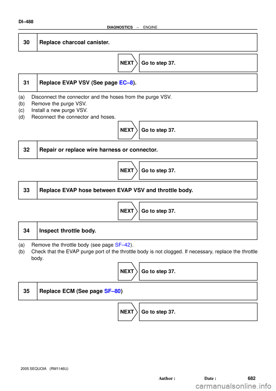
30 Replace charcoal canister.
NEXT Go to step 37.
31 Replace EVAP VSV (See page EC±8).
(a) Disconnect the connector and the hoses from the purge VSV.
(b) Remove the purge VSV.
(c) Install a new purge VSV.
(d) Reconnect the connector and hoses.
NEXT Go to step 37.
32 Repair or replace wire harness or connector.
NEXT Go to step 37.
33 Replace EVAP hose between EVAP VSV and throttle body.
NEXT Go to step 37.
34 Inspect throttle body.
(a) Remove the throttle body (see page SF±42).
(b) Check that the EVAP purge port of the throttle body is not clogged. If necessary, replace the throttle
body.
NEXT Go to step 37.
35 Replace ECM (See page SF±80)
NEXT Go to step 37.
Page 691 of 4323

36 Repair or replace parts and components indicated by output DTCs.
(a) Repair the malfunctioning areas indicated by the DTCs")
± DIAGNOSTICSENGINE
DI±489
683 Author�: Date�:
2005 SEQUOIA (RM1146U)
36 Repair or replace parts and components indicated by output DTCs.
(a) Repair the malfunctioning areas indicated by the DTCs that had been confirmed when the vehicle was
brought in.
NEXT Go to step 37.
37 Perform EVAP system auto operation check.
NOTICE:
�In the EVAP SYSTEM CHECK (AUTO OPERATION), the series of 4 EVAP SYSTEM CHECK steps
is performed automatically. It takes a maximum of approximately 15 minutes.
�Do not perform the EVAP SYSTEM CHECK when the fuel tank is more than 90 % full because
the cut±off valve may be closed and making the leak check of the fuel tank unavailable.
�Do not run the engine in this step.
�When the temperature of the fuel is 35�C (95�F) or more, a large amount of vapor forms and any
check results become inaccurate. When performing an EVAP SYSTEM CHECK, keep the tem-
perature below 35�C
(95�F).
(a) Clear DTCs (see page DI±43).
(b) On the hand±held tester, select the following menu items: DIAGNOSIS / ENHANCED OBD II / SYS-
TEM CHECK / EVAP SYS CHECK / AUTO OPERATION.
(c) After the SYSTEM CHECK is completed, check for pending DTCs by selecting the following menu
items: DIAGNOSIS / ENHANCED OBD II / DTC INFO / PENDING CODES.
HINT:
If no pending DTC is found, the repair has been successfully completed.
NEXT
Completed
Monitor Confirmation
HINT:
After a repair, check Monitor Status by performing the Key±Off Monitor Confirmation and Purge Flow Monitor
Confirmation described below.
1. KEY±OFF MONITOR CONFIRMATION
(a) Preconditions
The monitor will not run unless:
�The vehicle has been driven for 10 minutes or more (in a city area or on a free way)
�The fuel tank is less than 90 % full
�The altitude is less than 8,000 ft (2,400 m)
�The Engine Coolant Temperature (ECT) is between 4.4�C and 35�C (40�F and 95�F)
�The Intake Air Temperature (IAT) is between 4.4�C and 35�C (40�F and 95�F)
�The vehicle remains stationary (the vehicle speed is 0 mph [0 km/h])