Page 592 of 4323

Idling
IG SW OFF ECT:
75�C (167�F) or higher
Vehicle Speed
Warming up(d)(f)
10 minutes
or more(g)
10 seconds
or more4 seconds
or moreTime At Least 3 times
(h) (i)
(j) Accelera")
A23662
40 mph (64 km/h)
Idling
IG SW OFF ECT:
75�C (167�F) or higher
Vehicle Speed
Warming up(d)(f)
10 minutes
or more(g)
10 seconds
or more4 seconds
or moreTime At Least 3 times
(h) (i)
(j) Accelerator Pedal
DepressedAccelerator Pedal
Released (Fuel±cut)
DI±390
± DIAGNOSTICSENGINE
584 Author�: Date�:
2005 SEQUOIA (RM1146U)
CONFIRMATION DRIVING PATTERN
HINT:
This confirmation driving pattern is used in steps 2, 4, 7, 17 and 21 of the following diagnostic troubleshooting
procedure when using a hand±held tester.
(a) Connect the hand±held tester to DLC3.
(b) Turn the ignition switch to ON and turn the tester ON.
(c) Clear DTCs (see page DI±43).
(d) Start the engine, and warm it up until the ECT reaches 75�C (167�F) or higher.
(e) On the hand±held tester, select the following menu items: DIAGNOSIS/ENHANCED OBD II/DATA
LIST/FC IDL.
(f) Drive the vehicle at 40 mph (64 km/h) or more for at least 10 minutes.
(g) Change the transmission to 2nd gear.
(h) Drive the vehicle at proper vehicle speed to perform fuel±cut operation.
HINT:
Fuel±cut is performed under following conditions met:
�Accelerator pedal fully released.
�Engine speed 2,500 rpm or more (fuel injection returns at 1,000 rpm).
(i) Accelerate the vehicle to 30 mph (48 km/h) or more by depressing the accelerator pedal for at least
10 seconds.
(j) Soon after performing step (8) above, release the accelerator pedal for at least 4 seconds without de-
pressing the brake pedal, in order to execute fuel±cut control.
(k) Stop the vehicle and allow the engine to idle for 10 seconds or more.
(l) Allow the vehicle to decelerate until the vehicle speed declines to less than 6 mph (10 km/h).
(m) Repeat steps from (8) through (10) above at least 3 times in one driving cycle.
HINT:
Completing all A/F sensor monitors are required to change the value in TEST RESULT.
CAUTION:
Strictly observe of posted speed limits, traffic laws, and road conditions when performing these
drive pattern.
Page 595 of 4323

1 Check any other DTCs output (in addition to DTC P2195, P2196, P2197 or P2198).
PREPARATION:
(a) Connect a hand±held tester")
± DIAGNOSTICSENGINE
DI±393
587 Author�: Date�:
2005 SEQUOIA (RM1146U)
1 Check any other DTCs output (in addition to DTC P2195, P2196, P2197 or P2198).
PREPARATION:
(a) Connect a hand±held tester to the DLC3.
(b) Turn the ignition switch to ON and turn the tester ON.
(c) Select the following menu items: DIAGNOSIS / ENHANCED OBD II / DTC INFO / CURRENT CODES.
CHECK:
(a) Read DTCs.
Result:
Display (DTC Output)Proceed To
P2195, P2196, P2197 or P2198A
P2195, P2196, P2197 or P2198 and other DTCsB
HINT:
If any DTCs other than P2195, P2196, P2197 or P2198 are output, troubleshoot those DTCs first.
B Go to DTC chart (See page DI±58).
A
2 Check A/F sensor output current.
PREPARATION:
(a) Connect a hand±held tester to the DLC3.
(b) Turn the ignition switch to ON and turn the tester ON.
(c) Clear DTCs (see page DI±43).
(d) On the hand±held tester, select the following menu items: DIAGNOSIS/ENHANCED OBD II/MON-
ITOR INFO/MONITOR STATUS.
(e) Check that the status of O2S MON is COMPL.
(f) On the hand±held tester, select the following menu items: DIAGNOSIS/ENHANCED OBD II/MON-
ITOR INFO/TEST RESULT/RANGE BISI and B2S1.
(g) Check the test value of the air±fuel ratio sensor output current during fuel±cut.
RESULT:
Test ValueProceed to
Out of normal range (1.4 mA or more, and less than 3.6 mA)A
Within normal range (Less than 1.4 mA, or 3.6 mA or more)B
B Go to step 20.
A
Page 598 of 4323
DI±396
± DIAGNOSTICSENGINE
590 Author�: Date�:
2005 SEQUOIA (RM1146U)
6 Replace air fuel ratio sensor.
NEXT
7 Perform confirmation driving pattern.
NEXT
8 Check whether DTC output recurs (DTC P2195, P2196, P2197 or P2198)
CHECK:
(a) On the hand±held tester, select the following menu items: DIAGNOSIS / ENHANCED OBD II / DTC
INFO / PENDING CODES.
(b) Read DTCs.
RESULT:
Display (DTC Output)Proceed To
P2195, P2196, P2197 or P2198A
No outputB
B Go to step 5.
A
9 Confirm whether vehicle has run out of fuel in past.
NO Check for intermittent problems
(See page DI±11).
YES
DTC caused by running out of fuel.
Page 601 of 4323
± DIAGNOSTICSENGINE
DI±399
593 Author�: Date�:
2005 SEQUOIA (RM1146U)
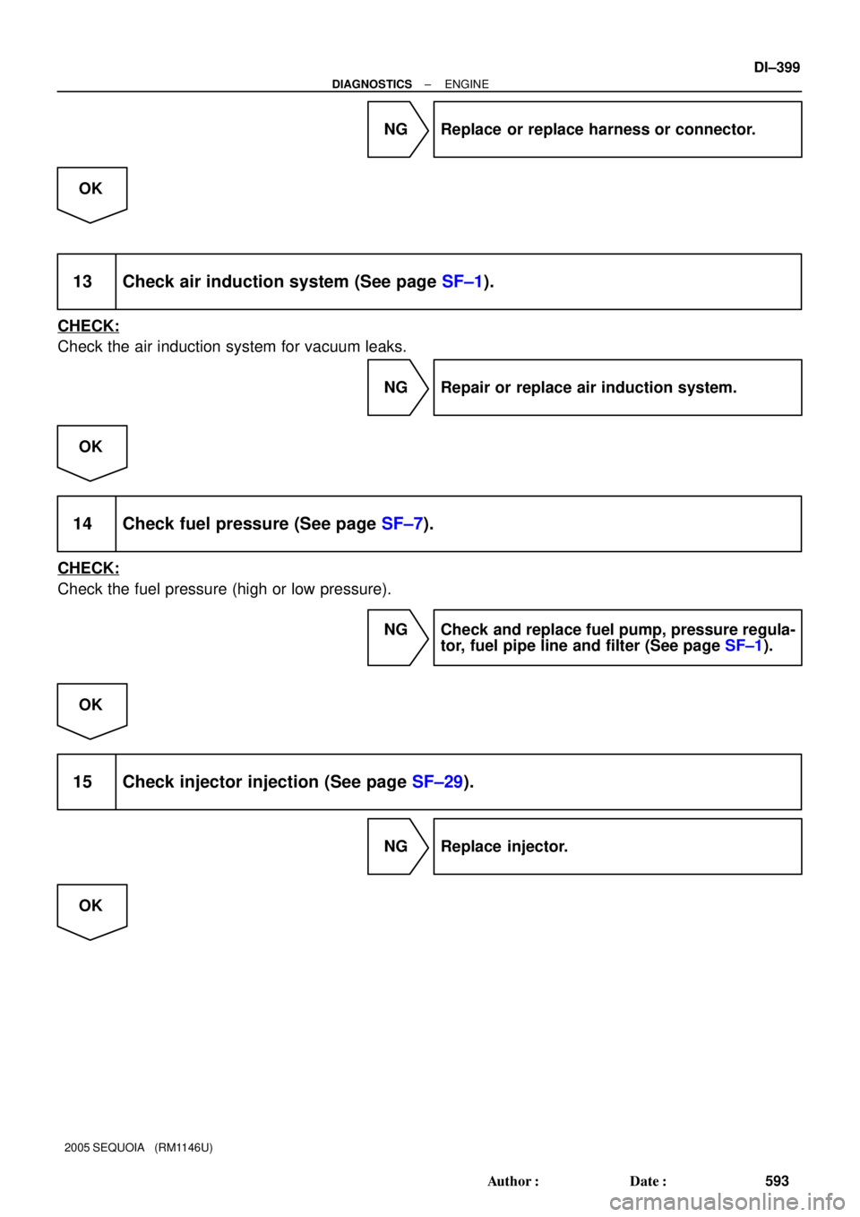
NG Replace or replace harness or connector.
OK
13 Check air induction system (See page SF±1).
CHECK:
Check the air induction system for vacuum leaks.
NG Repair or replace air induction system.
OK
14 Check fuel pressure (See page SF±7).
CHECK:
Check the fuel pressure (high or low pressure).
NG Check and replace fuel pump, pressure regula-
tor, fuel pipe line and filter (See page SF±1).
OK
15 Check injector injection (See page SF±29).
NG Replace injector.
OK
Page 602 of 4323
DI±400
± DIAGNOSTICSENGINE
594 Author�: Date�:
2005 SEQUOIA (RM1146U)
16 Replace air fuel ratio sensor.
NEXT
17 Perform confirmation driving pattern.
NEXT
18 Check whether DTC output recurs (DTC P2195, P2196, P2197 or P2198)
CHECK:
(a) On the hand±held tester, select the following menu items: DIAGNOSIS / ENHANCED OBD II / DTC
INFO / PENDING CODES.
(b) Read DTCs.
RESULT:
Display (DTC Output)Proceed To
P2195, P2196, P2197 or P2198A
No outputB
B Replace ECM (See page SF±80) and perform
confirmation driving pattern.
A
19 Confirm whether vehicle has run out of fuel in past.
NO Check for intermittent problems
(See page DI±11).
YES
DTC caused by running out of fuel.
Page 603 of 4323
± DIAGNOSTICSENGINE
DI±401
595 Author�: Date�:
2005 SEQUOIA (RM1146U)
20 Replace air fuel ratio sensor.
NEXT
21 Perform confirmation driving pattern.
NEXT
22 Check whether DTC output recurs (DTC P2195, P2196, P2197 or P2198)
CHECK:
(a) On the hand±held tester, select the following menu items: DIAGNOSIS / ENHANCED OBD II / DTC
INFO / PENDING CODES.
(b) Read DTCs.
RESULT:
Display (DTC Output)Proceed To
P2195, P2196, P2197 or P2198 (A/F sensor pending DTCs)A
No outputB
B Replace ECM (See page SF±80).
A
END
Page 605 of 4323

CIRCUIT DESCRIPTION
Refer to DTC P2195 on page DI±383.
DTC No.DTC Detection ConditionsTrouble Areas
P2238
P2241
�Case 1:
Con")
± DIAGNOSTICSENGINE
DI±403
597 Author�: Date�:
2005 SEQUOIA (RM1146U)
CIRCUIT DESCRIPTION
Refer to DTC P2195 on page DI±383.
DTC No.DTC Detection ConditionsTrouble Areas
P2238
P2241
�Case 1:
Condition (a) or (b) continues for 5.0 seconds or more
(1 trip detection logic):
(a) AF+ voltage 0.5 V or less
(b) (AF+) ± (AF±) = 0.1 V or less
�Case 2:
A/F sensor admittance: Less than 0.022 1/W
(1 trip detection logic)
�Open or short in A/F sensor (sensor 1) circuit
�A/F sensor (sensor 1)
�A/F sensor heater
�EFI relay
�A/F sensor heater and relay circuits
�ECM
P2239
P2242AF+ voltage more than 4.5 V for 5.0 seconds or more
(1 trip detection logic)
�Open or short in A/F sensor (sensor 1) circuit
�A/F sensor (sensor 1)
�A/F sensor heater
�EFI relay
�A/F sensor heater and relay circuits
�ECM
P2252
P2255AF± voltage 0.5 V or less for 5.0 seconds or more
(1 trip detection logic)
�Open or short in A/F sensor (sensor 1) circuit
�A/F sensor (sensor 1)
�A/F sensor heater
�EFI relay
�A/F sensor heater and relay circuits
�ECM
P2253
P2256AF± voltage more than 4.5 V for 5.0 seconds or more
(1 trip detection logic)
�Open or short in A/F sensor (sensor 1) circuit
�A/F sensor (sensor 1)
�A/F sensor heater
�EFI relay
�A/F sensor heater and relay circuits
�ECM
MONITOR DESCRIPTION
The Air±Fuel Ratio (A/F) sensor varies its output voltage in proportion to the air±fuel ratio. If the A/F sensor
impedance (alternating current resistance) or voltage output deviates greatly from the standard range, the
ECM determines that there is an open or short malfunction in the A/F sensor circuit.
Page 606 of 4323

MONITOR STRATEGY
A/F sensor (Bank 1) open circuit between AF+
and AF±
P2238A/F sensor (Bank 1) short circuit between AF+
and")
DI±404
± DIAGNOSTICSENGINE
598 Author�: Date�:
2005 SEQUOIA (RM1146U)
MONITOR STRATEGY
A/F sensor (Bank 1) open circuit between AF+
and AF±
P2238A/F sensor (Bank 1) short circuit between AF+
and AF±
A/F sensor (Bank 1) short circuit between AF+
and GND
P2239A/F sensor (Bank 1) short circuit between AF+
and +B
A/F sensor (Bank 2) open circuit between AF+
and AF±
RltdDTC
P2241A/F sensor (Bank 2) short circuit between AF+
and AF±
Related DTCsA/F sensor (Bank 2) short circuit between AF+
and GND
P2242A/F sensor (Bank 2) short circuit between AF+
and +B
P2252A/F sensor (Bank 1) short circuit between AF±
and GND
P2253A/F sensor (Bank 1) short circuit between AF±
and +B
P2255A/F sensor (Bank 2) short circuit between AF±
and GND
P2256A/F sensor (Bank 2) short circuit between AF±
and +B
Required sensors/componentsA/F sensor
Frequency of operationOnce per driving cycle
Duration10 sec.: A/F sensor open circuit between AF+ and AF±
5 sec.: Others
MIL operationImmediate
Sequence of operationNone
TYPICAL ENABLING CONDITIONS
ItSpecificationItemMinimumMaximum
The monitor will run whenever these
DTCs are not presentSee page DI±18
P2238, P2241 (A/F sensor open circuit between AF+ and AF±):
Duration while all of following conditions
met20 sec.±
AF+ terminal voltage0.5 to 4.5 V
AF± terminal voltage0.5 to 4.5 V
Difference between AF+ terminal and AF±
terminal voltage0.1 to 0.8 V
ECT20°C (68°F)±
EngineRunning
Time after engine start20 sec.±
Fuel±cutOFF
A/F sensor heater duty cycle0%±