Page 902 of 4323

DIDCN±01
F19465
: CAN
Compressor Assy
Combination Meter
Suspension
Control
ECU Exhaust Solenoid
Valve
Gate Solenoid Valve
Leveling Solenoid ValveAIR SUS Relay
Height Control Cylinder
(Pneumatic Cylinder)
Height Control Sensor
Sub±assy : ECU Output Signal
: ECU Input Signal
: Air Flow Path
Dryer
Height Control Cylinder
(Pneumatic Cylinder)� Speed Sensors
� Engine Speed
� L4 Switch
� Shift Position
Information
� Transmission
Model Informa-
tion
� Height Control Mode Select
Switch
� Height Control Switch
� Courtesy Light Switches
� Stop Light SwitchHI
N
LO
MAN. DI±700
± DIAGNOSTICSAIR SUSPENSION SYSTEM
894 Author�: Date�:
2005 SEQUOIA (RM1146U)
SYSTEM DESCRIPTION
1. GENERAL
�This system uses pneumatic cylinders instead of the coil springs that are used in a conventional rear
suspension. The suspension control ECU analyzes the information based on the switches, sensors,
and input signals, operates the compressor assy, and uses the solenoid valves to control the vehicle
height.
�The suspension control ECU detects, via the height control sensor, the changes in the rear vehicle
height that results from the number of occupants or the amount of the load. Then, the suspension con-
trol ECU controls the height control solenoid valves and the compressor assy in order to automatically
adjust the rear vehicle height to a constant (normal) vehicle height.
�Furthermore, three vehicle heights can be selected by operating the height control switch: HI, NOR-
MAL, and LO. The HI vehicle height ensures the vehicle's drive±through performance on rough roads.
The LO vehicle height facilitates the entry and exit of the occupants and the loading and unloading
of cargo. The NORMAL vehicle height helps realize excellent controllability and riding comfort during
normal driving.
Page 2096 of 4323

TERMINALS OF ECU
1. CHECK BODY ECU
(a) Disconnect the B5, B6 and B7 ECU con")
DIDFA±01
I27698
B5
B6B7
DI±1894
± DIAGNOSTICSMULTIPLEX COMMUNICATION SYSTEM
2088 Author�: Date�:
2005 SEQUOIA (RM1146U)
TERMINALS OF ECU
1. CHECK BODY ECU
(a) Disconnect the B5, B6 and B7 ECU connectors.
(b) Measure the resistance or voltage of each terminal of the wire harness side connector.
Standard:
Symbols (Terminal No.)Wiring ColorTerminal DescriptionConditionSpecified Condition
BDR (B6±2) ±
Body groundL±W ± Body ground+B (BATT) power supplyAlways10 to 14 V
IG (B7±6) ± Body groundB±R ± Body groundIgnition power supplyIgnition switch ON10 to 14 V
ACC (B7±10) ±
Body groundGR ± Body groundACC power supplyIgnition switch ACC10 to 14 V
OBD2 (B5±2) ±
Body groundG±R ± Body groundBus º+º lineDuring transmissionPulse generation
S+B (B6±1) ± Body groundW±L ± Body ground+B (BATT) power supplyAlways10 to 14 V
BECU (B6±5) ±
Body groundW±R ± Body ground+B (BATT) power supplyAlways10 to 14 V
WIG (B7±5) ± Body groundL±Y ± Body groundIgnition power supplyIgnition switch ON10 to 14 V
MPX3 (B7±20) ±
Body groundG±O ± Body groundMPX lineAlways10 kW or higher
MPX2 (B5±24) ±
Body groundL±Y ± Body groundMPX lineAlways10 kW or higher
MPX1 (B7±22) ±
Body groundW±L ± Body groundMPX lineAlways10 kW or higher
GND1 (B6±6) ±
Body groundW±B ± Body groundGroundAlwaysBelow 1 W
PRG ± GND1
(B5±5 ± B6±6)V ± W±BWireless transmitter signal
groundWireless door look receiver
communication circuit±
RDA ± GND1
(B5±4 ± B6±6)R±G ± W±BWireless transmitter signal
inputWireless door lock control
system is operatedBelow 1 V
RDA ± GND1
(B5±4 ± B6±6)R±G ± W±BWireless transmitter signal
inputWireless door lock control
system is not operated10 to 14 V
GSW
(B6±16)GR±RAir bag sensor commu-
nication signalAir bag sensor commu-
nication circuit±
CLTS (*1) ± GND1
(B6±12 ± B6±6)Y ± W±BAutomatic light control sen-
sor (Signal)Ignition switch OFFBelow 1 V
CLTS (*1) ± GND1
(B6±12 ± B6±6)Y ± W±BAutomatic light control sen-
sor (Signal)Ignition switch ONSignal waveform
CLTE (*1) ± GND1
(B6±3 ± B6±6)BR ± W±BAutomatic light control sen-
sor (Ground)AlwaysBelow 1 V
Page 2515 of 4323

A04550
12345678
9 1 0 111 21 31 41 51 6
DLC3
I15897
AUTO S/W
R/F S/W
AC2163
Blinking Pattern
4 times
1 sec.
1 sec.
ON
OFF
± DIAGNOSTICSAIR CONDITIONING SYSTEM
DI±2313
2507 Author�: Date�:
2005 SEQUOIA (RM1146U)
3. CHECK DLC3
The vehicle's ECM uses the ISO 9141±2 communication proto-
col. The terminal arrangement of the DLC3 complies with SAE
J1962 and matches the ISO 9141±2 format.
Symbols (Terminal No.)Terminal DescriptionConditionSpecified Condition
SIL (7) ± SG (5)Bus º+º lineDuring transmissionPulse generation
CG (4) ± Body groundChassis groundAlwaysBelow 1 W
SG (5) ± Body groundSignal groundAlwaysBelow 1 W
BAT (16) ± Body groundBattery positiveAlways11 to 14 V
4. INDICATOR CHECK
(a) Turn the ignition switch on while pressing the A/C control
AUTO switch and R/F SW simultaneously.
(b) Check that all the indicators light up and go off at 1 second
intervals 4 times in succession.
HINT:
�After the indicator check is ended, the diagnostic trouble
code check begins automatically.
�Press the OFF switch when desiring to cancel the check
mode.
Page 2917 of 4323
AT130±01
± AUTOMATIC TRANSMISSION (A750E, A750F)AUTOMATIC TRANSMISSION SYSTEM
AT±1
2909 Author�: Date�:
2005 SEQUOIA (RM1146U)
AUTOMATIC TRANSMISSION SYSTEM
PRECAUTION
NOTICE:
When disconnecting the battery terminal, initialize the following system after the terminal is recon-
nected.
System NameSee Page
Back Door Power Window Control SystemBE±77
Page 2918 of 4323
AT131±01
D14123
Clutch No.2 (C2) Clutch No.3 (C
3)
Clutch No.1 (C
1)One±way Clutch
No.1 (F1)
One±way Clutch
No.2 (F
2)
Brake No.3
(B
3)
Brake No.1 (B1)
Brake No.2 (B2)One±way Clutch
No.3 (F
3)Brake No.4 (B4)
Shift Solenoid Valve SLT
Shift Solenoid Valve SL1Shift Solenoid Valve S1
Shift Solenoid Valve S2Shift Solenoid Valve SR Shift Solenoid Valve SL2Shift Solenoid Valve SLU
AT±2
± AUTOMATIC TRANSMISSION (A750E, A750F)AUTOMATIC TRANSMISSION SYSTEM
2910 Author�: Date�:
2005 SEQUOIA (RM1146U)
OPERATION
Page 2919 of 4323
SL1
Park
Reverse
Neutral
1st
2nd
4th
5th
1st
4th
1st
3rd
1st
1st
S1C1C2B1B2B3B4F3F1F2
: Operates
Gear
Position Shift Lever
Position
2nd
2nd
2nd3rd 3rd
R
N
D
D
(O/D OFF)
3
2
L P
S2 SR
SL2C3SLU
F1, F2, F3 : Operates only when driving
± AUTOMATIC TRANSMISSION (A750E, A750F)AUTOMATIC TRANSMISSION SYSTEM
AT±3
2911 Author�: Date�:
2005 SEQUOIA (RM1146U)
Page 2920 of 4323
D13867
AT132±01
OR0004
SST
OR0005
SST
AT±4
± AUTOMATIC TRANSMISSION (A750E, A750F)EXTENSION HOUSING OIL SEAL (A750E)
2912 Author�: Date�:
2005 SEQUOIA (RM1146U)
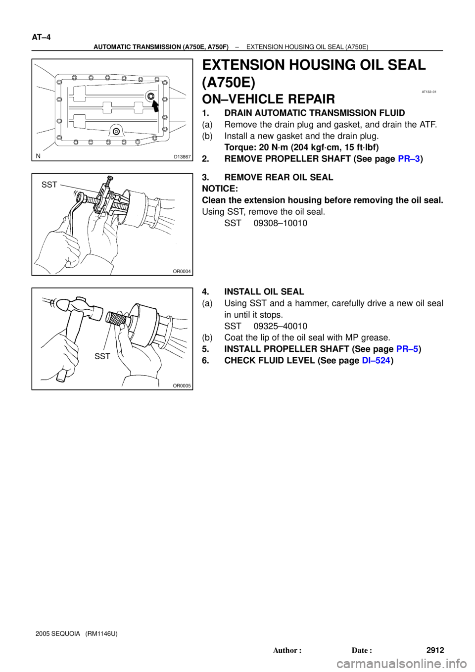
EXTENSION HOUSING OIL SEAL
(A750E)
ON±VEHICLE REPAIR
1. DRAIN AUTOMATIC TRANSMISSION FLUID
(a) Remove the drain plug and gasket, and drain the ATF.
(b) Install a new gasket and the drain plug.
Torque: 20 N´m (204 kgf´cm, 15 ft´lbf)
2. REMOVE PROPELLER SHAFT (See page PR±3)
3. REMOVE REAR OIL SEAL
NOTICE:
Clean the extension housing before removing the oil seal.
Using SST, remove the oil seal.
SST 09308±10010
4. INSTALL OIL SEAL
(a) Using SST and a hammer, carefully drive a new oil seal
in until it stops.
SST 09325±40010
(b) Coat the lip of the oil seal with MP grease.
5. INSTALL PROPELLER SHAFT (See page PR±5)
6. CHECK FLUID LEVEL (See page DI±524)
Page 2921 of 4323
D13884
A750E:
A750F:AT133±01
D13885
A750E:
A750F:
± AUTOMATIC TRANSMISSION (A750E, A750F)SPEED SENSOR
AT±5
2913 Author�: Date�:
2005 SEQUOIA (RM1146U)
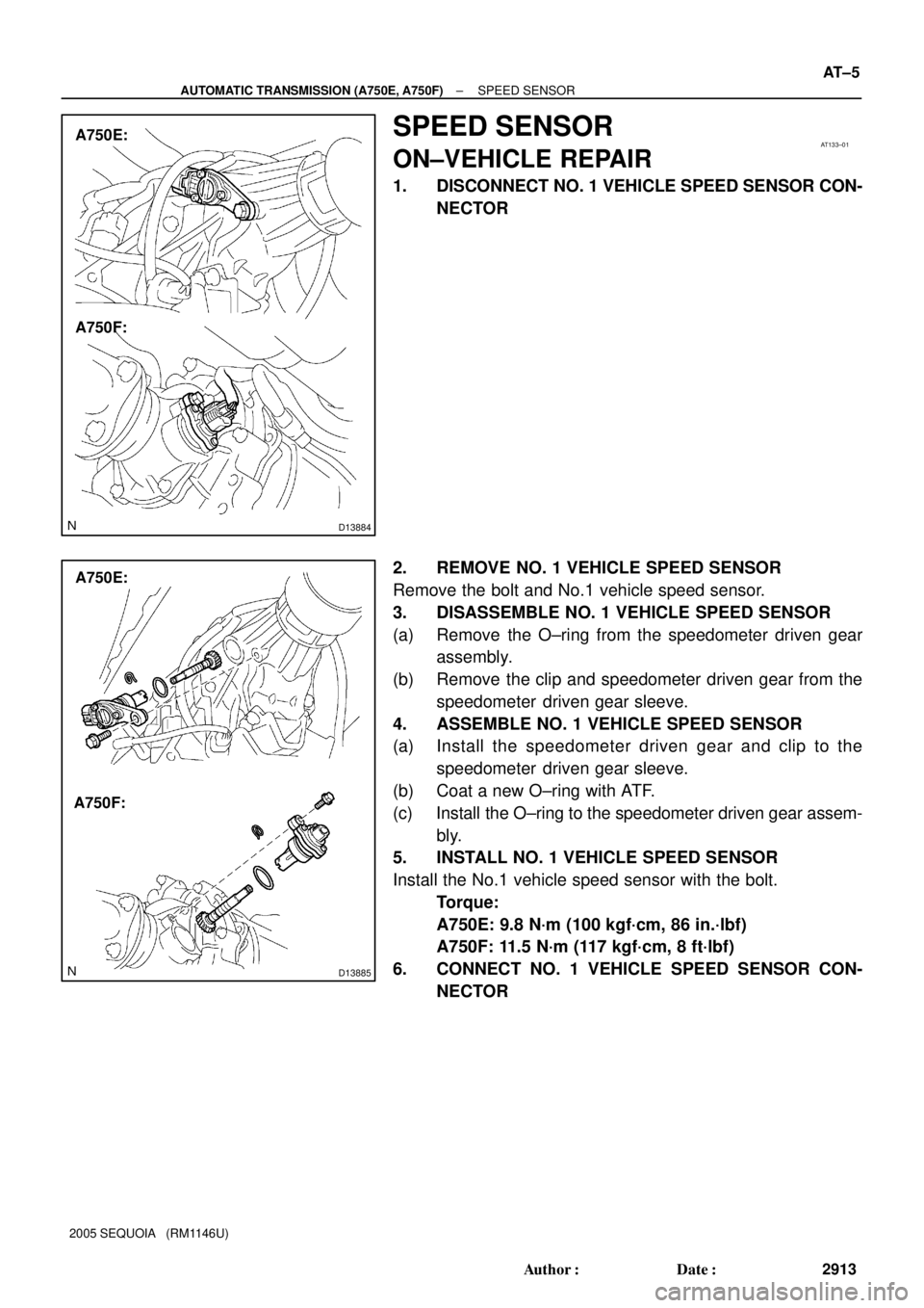
SPEED SENSOR
ON±VEHICLE REPAIR
1. DISCONNECT NO. 1 VEHICLE SPEED SENSOR CON-
NECTOR
2. REMOVE NO. 1 VEHICLE SPEED SENSOR
Remove the bolt and No.1 vehicle speed sensor.
3. DISASSEMBLE NO. 1 VEHICLE SPEED SENSOR
(a) Remove the O±ring from the speedometer driven gear
assembly.
(b) Remove the clip and speedometer driven gear from the
speedometer driven gear sleeve.
4. ASSEMBLE NO. 1 VEHICLE SPEED SENSOR
(a) Install the speedometer driven gear and clip to the
speedometer driven gear sleeve.
(b) Coat a new O±ring with ATF.
(c) Install the O±ring to the speedometer driven gear assem-
bly.
5. INSTALL NO. 1 VEHICLE SPEED SENSOR
Install the No.1 vehicle speed sensor with the bolt.
Torque:
A750E: 9.8 N´m (100 kgf´cm, 86 in.´lbf)
A750F: 11.5 N´m (117 kgf´cm, 8 ft´lbf)
6. CONNECT NO. 1 VEHICLE SPEED SENSOR CON-
NECTOR

 Clutch No.3 (C
3)
Clutch No.1 (C
1)One±way Clutch
No.1 (F1)
One±way Clutch
No.2 (F
2)
Brake No.3
(B
3)
Brake No.1 (B1)
Brake No.2 (B2)One±way Clutch
No.3 (F
3)Brak")

3
2
L P
S2 SR
SL2C3SLU
F")