Page 3326 of 4323
RS119±01
H16182
H23213
H23214
± SUPPLEMENTAL RESTRAINT SYSTEMFRONT PASSENGER AIRBAG ASSEMBLY
RS±35
3318 Author�: Date�:
2005 SEQUOIA (RM1146U)
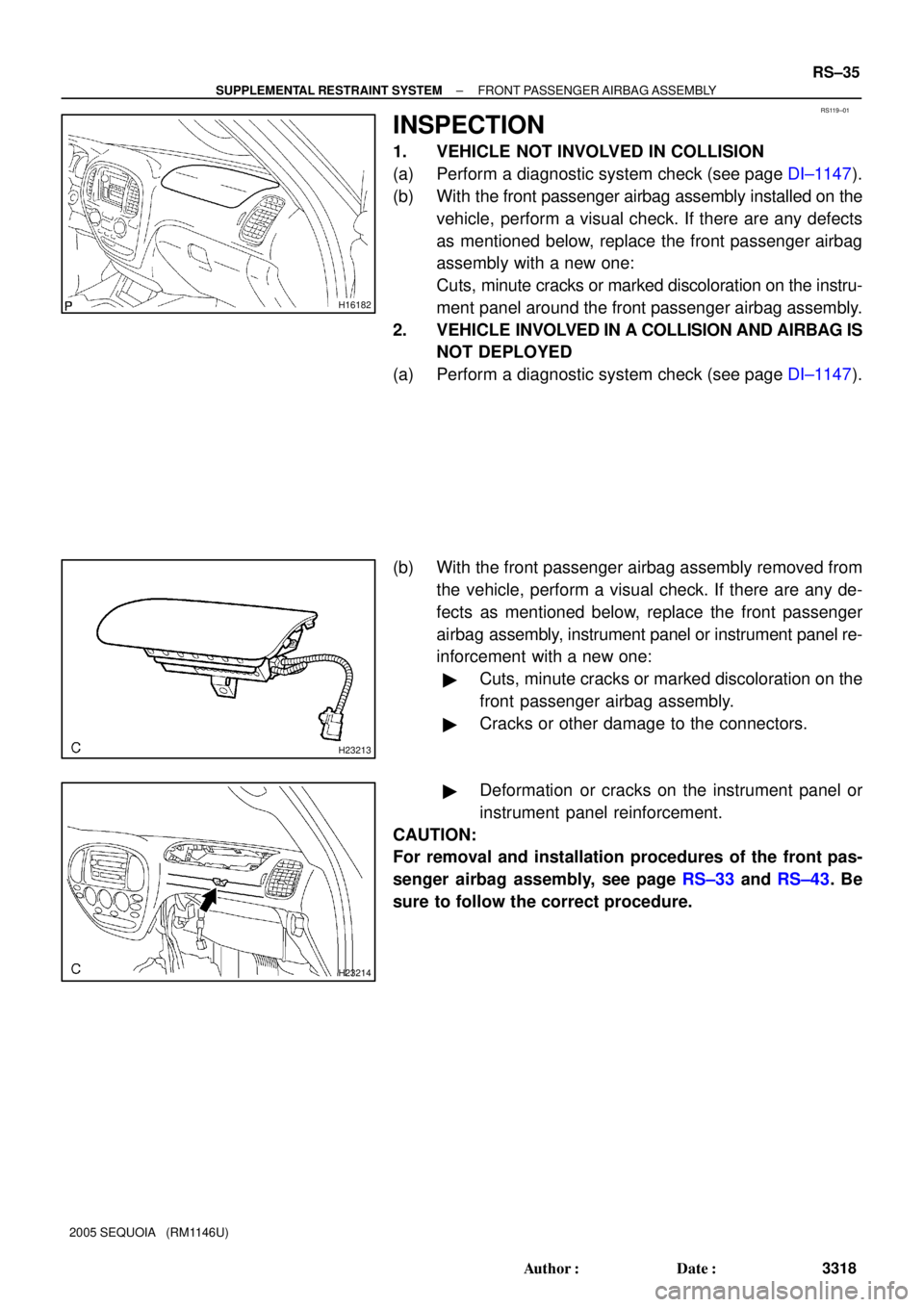
INSPECTION
1. VEHICLE NOT INVOLVED IN COLLISION
(a) Perform a diagnostic system check (see page DI±1147).
(b) With the front passenger airbag assembly installed on the
vehicle, perform a visual check. If there are any defects
as mentioned below, replace the front passenger airbag
assembly with a new one:
Cuts, minute cracks or marked discoloration on the instru-
ment panel around the front passenger airbag assembly.
2. VEHICLE INVOLVED IN A COLLISION AND AIRBAG IS
NOT DEPLOYED
(a) Perform a diagnostic system check (see page DI±1147).
(b) With the front passenger airbag assembly removed from
the vehicle, perform a visual check. If there are any de-
fects as mentioned below, replace the front passenger
airbag assembly, instrument panel or instrument panel re-
inforcement with a new one:
�Cuts, minute cracks or marked discoloration on the
front passenger airbag assembly.
�Cracks or other damage to the connectors.
�Deformation or cracks on the instrument panel or
instrument panel reinforcement.
CAUTION:
For removal and installation procedures of the front pas-
senger airbag assembly, see page RS±33 and RS±43. Be
sure to follow the correct procedure.
Page 3333 of 4323
RS0BI±07
RS±42
± SUPPLEMENTAL RESTRAINT SYSTEMFRONT PASSENGER AIRBAG ASSEMBLY
3325 Author�: Date�:
2005 SEQUOIA (RM1146U)
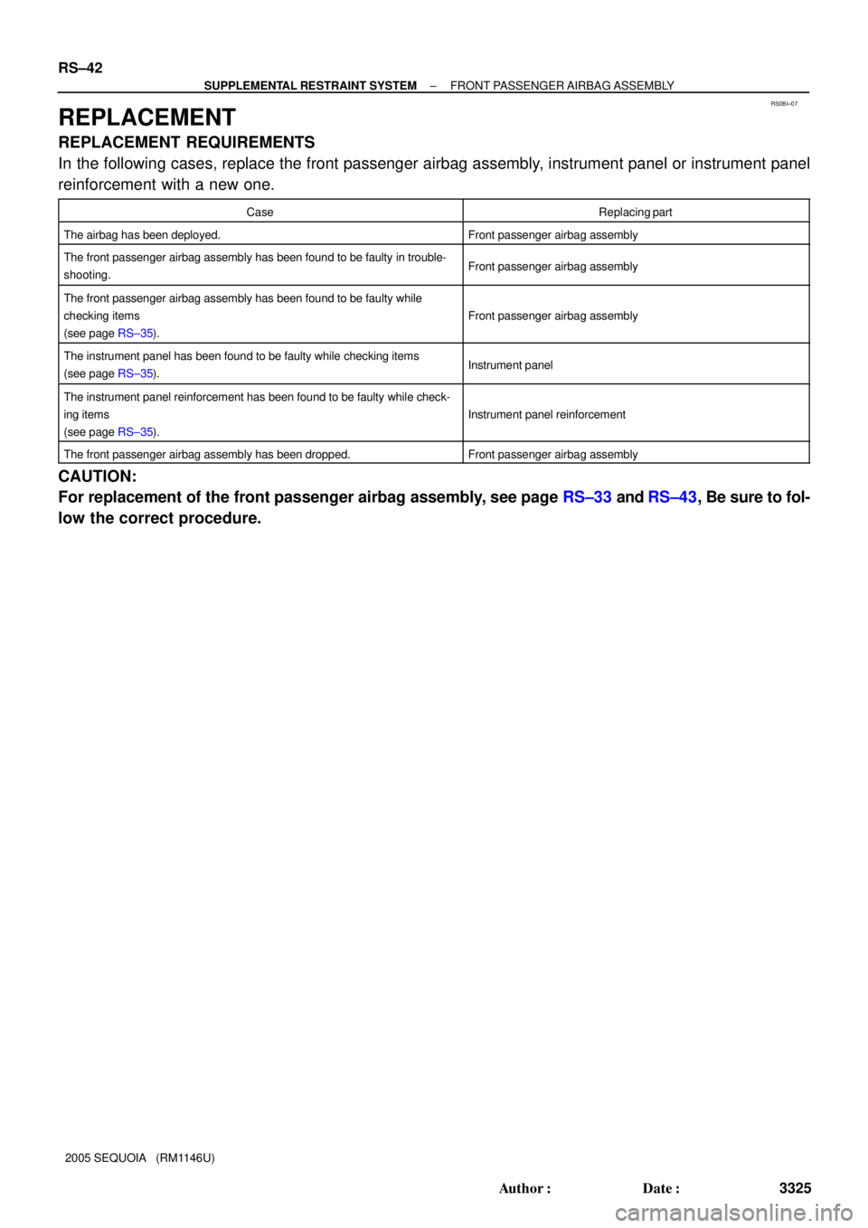
REPLACEMENT
REPLACEMENT REQUIREMENTS
In the following cases, replace the front passenger airbag assembly, instrument panel or instrument panel
reinforcement with a new one.
CaseReplacing part
The airbag has been deployed.Front passenger airbag assembly
The front passenger airbag assembly has been found to be faulty in trouble-
shooting.Front passenger airbag assembly
The front passenger airbag assembly has been found to be faulty while
checking items
(see page RS±35).
Front passenger airbag assembly
The instrument panel has been found to be faulty while checking items
(see page RS±35).Instrument panel
The instrument panel reinforcement has been found to be faulty while check-
ing items
(see page RS±35).
Instrument panel reinforcement
The front passenger airbag assembly has been dropped.Front passenger airbag assembly
CAUTION:
For replacement of the front passenger airbag assembly, see page RS±33 and RS±43, Be sure to fol-
low the correct procedure.
Page 3334 of 4323
RS0T8±03
H23212
± SUPPLEMENTAL RESTRAINT SYSTEMFRONT PASSENGER AIRBAG ASSEMBLY
RS±43
3326 Author�: Date�:
2005 SEQUOIA (RM1146U)
INSTALLATION
NOTICE:
�If the front passenger airbag assembly has been
dropped, or there are cracks, dents or other defects
in the case or connector, replace the front passenger
airbag assembly with a new one.
�When installing the front passenger airbag assembly,
take care it is not pinched between other parts.
�Never use airbag parts from another vehicle. When
replacing parts, replace them with new ones.
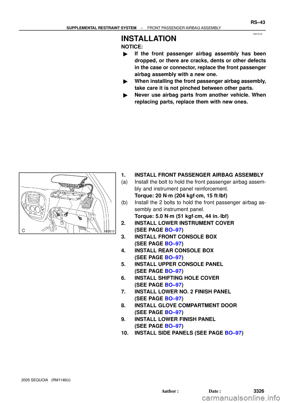
1. INSTALL FRONT PASSENGER AIRBAG ASSEMBLY
(a) Install the bolt to hold the front passenger airbag assem-
bly and instrument panel reinforcement.
Torque: 20 N´m (204 kgf´cm, 15 ft´lbf)
(b) Install the 2 bolts to hold the front passenger airbag as-
sembly and instrument panel.
Torque: 5.0 N´m (51 kgf´cm, 44 in.´lbf)
2. INSTALL LOWER INSTRUMENT COVER
(SEE PAGE BO±97)
3. INSTALL FRONT CONSOLE BOX
(SEE PAGE BO±97)
4. INSTALL REAR CONSOLE BOX
(SEE PAGE BO±97)
5. INSTALL UPPER CONSOLE PANEL
(SEE PAGE BO±97)
6. INSTALL SHIFTING HOLE COVER
(SEE PAGE BO±97)
7. INSTALL LOWER NO. 2 FINISH PANEL
(SEE PAGE BO±97)
8. INSTALL GLOVE COMPARTMENT DOOR
(SEE PAGE BO±97)
9. INSTALL LOWER FINISH PANEL
(SEE PAGE BO±97)
10. INSTALL SIDE PANELS (SEE PAGE BO±97)
Page 3414 of 4323
BE19B±08
BE±2
± BODY ELECTRICALTROUBLESHOOTING
3406 Author�: Date�:
2005 SEQUOIA (RM1146U)
TROUBLESHOOTING
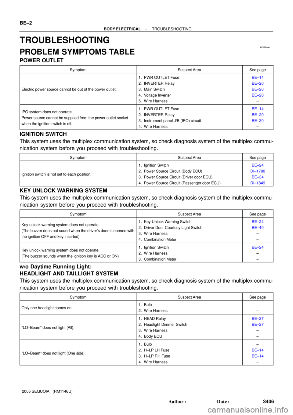
PROBLEM SYMPTOMS TABLE
POWER OUTLET
SymptomSuspect AreaSee page
Electric power source cannot be out of the power outlet.
1. PWR OUTLET Fuse
2. INVERTER Relay
3. Main Switch
4. Voltage Inverter
5. Wire HarnessBE±14
BE±20
BE±20
BE±20
±
IPO system does not operate.
Power source cannot be supplied from the power outlet socket
when the ignition switch is off.1. PWR OUTLET Fuse
2. INVERTER Relay
3. Instrument panel J/B (IPO) circuit
4. Wire HarnessBE±14
BE±20
BE±20
±
IGNITION SWITCH
This system uses the multiplex communication system, so check diagnosis system of the multiplex commu-
nication system before you proceed with troubleshooting.
SymptomSuspect AreaSee page
Ignition switch is not set to each position.
1. Ignition Switch
2. Power Source Circuit (Body ECU)
3. Power Source Circuit (Driver door ECU)
4. Power Source Circuit (Passenger door ECU)BE±24
DI±1700
BE±34
DI±1849
KEY UNLOCK WARNING SYSTEM
This system uses the multiplex communication system, so check diagnosis system of the multiplex commu-
nication system before you proceed with troubleshooting.
SymptomSuspect AreaSee page
Key unlock warning system does not operate.
(The buzzer does not sound when the driver's door is opened with
the ignition OFF and key inserted)1. Key Unlock Warning Switch
2. Driver Door Courtesy Light Switch
3. Wire Harness
4. Combination MeterBE±24
BE±40
±
±
Key unlock warning system does not operate.
(The buzzer sounds when the ignition key is ACC or ON)1. Ignition Switch
2. Wire Harness
3. Combination MeterBE±24
±
±
w/o Daytime Running Light:
HEADLIGHT AND TAILLIGHT SYSTEM
This system uses the multiplex communication system, so check diagnosis system of the multiplex commu-
nication system before you proceed with troubleshooting.
SymptomSuspect AreaSee page
Only one headlight comes on.1. Bulb
2. Wire Harness±
±
ºLO±Beamº does not light (All).
1. HEAD Relay
2. Headlight Dimmer Switch
3. Wire Harness
4. Body ECUBE±27
BE±27
±
±
ºLO±Beamº does not light (One side).
1. Bulb
2. H±LP LH Fuse
3. H±LP RH Fuse
4. Wire Harness±
BE±14
BE±14
±
Page 3418 of 4323
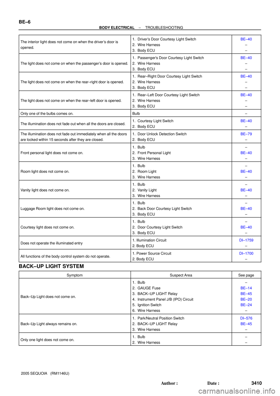
BE±6
± BODY ELECTRICALTROUBLESHOOTING
3410 Author�: Date�:
2005 SEQUOIA (RM1146U) The interior light does not come on when the driver's door is
opened.
1. Driver's Door Courtesy Light Switch
2. Wire Harness
3. Body ECUBE±40
±
±
The light does not come on when the passenger's door is opened.
1. Passenger's Door Courtesy Light Switch
2. Wire Harness
3. Body ECUBE±40
±
±
The light does not come on when the rear±right door is opened.
1. Rear±Right Door Courtesy Light Switch
2. Wire Harness
3. Body ECUBE±40
±
±
The light does not come on when the rear±left door is opened.
1. Rear±Left Door Courtesy Light Switch
2. Wire Harness
3. Body ECUBE±40
±
±
Only one of the bulbs comes on.Bulb±
The illumination does not fade out when all the doors are closed.1. Courtesy Light Switch
2. Body ECUBE±40
±
The illumination does not fade out immediately when all the doors
are locked within 15 seconds after they are closed.1. Door Unlock Detection Switch
2. Body ECUBE±79
±
Front personal light does not come on.
1. Bulb
2. Front Personal Light
3. Wire Harness±
BE±40
±
Room light does not come on.
1. Bulb
2. Room Light
3. Wire Harness±
BE±40
±
Vanity light does not come on.
1. Bulb
2. Vanity Light
3. Wire Harness±
BE±40
±
Luggage Room light does not come on.
1. Bulb
2. Back Door Courtesy Light Switch
3. Body ECU±
BE±40
±
Courtesy light does not come on.
1. Bulb
2. Door Courtesy Light Switch
3. Body ECU±
BE±40
±
Does not operate the illuminated entry1. Illumination Circuit
2. Body ECUDI±1759
±
All functions of the body control system do not operate.1. Power Source Circuit
2. Body ECUDI±1700
±
BACK±UP LIGHT SYSTEM
SymptomSuspect AreaSee page
Back±Up Light does not come on.
1. Bulb
2. GAUGE Fuse
3. BACK±UP LIGHT Relay
4. Instrument Panel J/B (IPO) Circuit
5. Ignition Switch
6. Wire Harness±
BE±14
BE±45
BE±20
BE±24
±
Back±Up Light always remains on.
1. Park/Neutral Position Switch
2. BACK±UP LIGHT Relay
3. Wire HarnessDI±576
BE±45
±
Only one light does not come on.1. Bulb
2. Wire Harness±
±
Page 3426 of 4323
BE2DG±03
I28397
Engine Room R/B No. 2
Engine Room J/B
� FL Block
Instrument Panel J/B
Driver Side R/BEngine Room R/B No. 3 FL Block:
A
B
B
A
B
Engine Room R/B
No. 4
NOTICE:
When removing the FL block, pinch ºAº using pliers and pull it out.
Since ºBº is easy to damage, do not pinch with pliers. BE±14
± BODY ELECTRICALPOWER SOURCE
3418 Author�: Date�:
2005 SEQUOIA (RM1146U)
POWER SOURCE
LOCATION
Page 3428 of 4323
I18638
A. Taillight Relay Instrument Panel J/B:
Relays:
B. Back±Up Light Relay
C. ACC Relay
D. Power Main Relay
E. Fog Light Relay
F. MIRROR HEATER Relay
G. FLASHER Relay
H. SEAT HEATER Relay
Fuses:
1. TAIL Fuse
2. PWR No. 4 Fuse
3. PANEL Fuse
4. ECU±IG Fuse
123
4567
89
1011
12
1314
A
BC
DE
GH
F
15
1617 18 19
20
21 22 23
2425
265. CIG Fuse
6. PWR No. 1 Fuse
7. HTR Fuse
8. WSH Fuse
9. RAD No. 2 Fuse
10. WIP Fuse
11. FOG Fuse
12. AC INV Fuse 15 A
13. 4WD Fuse14. IGN1 Fuse
15. GAUGE Fuse
16. IGN 2 Fuse
17. STOP Fuse
18. SUN ROOF Fuse
19. PWR OUTLET Fuse
20. PWR No. 3 Fuse
21. OBD Fuse
22. PWR No. 2 Fuse
23. SEAT HTR Fuse
24. PWR SEAT Fuse
25. AM1 Fuse
26. PWR No. 5 Fuse 15 A 10 A
20 A
7.5 A
10 A
15 A
25 A
10 A
25 A
7.5 A
25 A
15 A
20 A15 A
20 A
15 A
25 A
15 A
20 A
7.5 A
25 A
15 A
30 A
40 A
30 A BE±16
± BODY ELECTRICALPOWER SOURCE
3420 Author�: Date�:
2005 SEQUOIA (RM1146U)
Page 3431 of 4323
BE2DE±03
I28400
Power Outlet (12 V)
Power Outlet
(115 V) (*1)
(12 V) (*2) Ignition Switch
Main Switch
Instrument Panel J/B
� IPO (Intelligent Power Outlet)
� AC INV Fuse
Driver Side R/B
� INVERTER Relay
� PWR OUTLET Fuse
Power Outlet (12 V)
*1: w/ Rear Seat Entertainment System
w/ Rear Seat Audio System
*2: w/o Rear Seat Entertainment System
w/o Rear Seat Audio System
Voltage Inverter
(Located inside of the
quarter trim panel LH)
Cigarette Lighter
± BODY ELECTRICALPOWER OUTLET
BE±19
3423 Author�: Date�:
2005 SEQUOIA (RM1146U)
POWER OUTLET
LOCATION