Page 886 of 4323
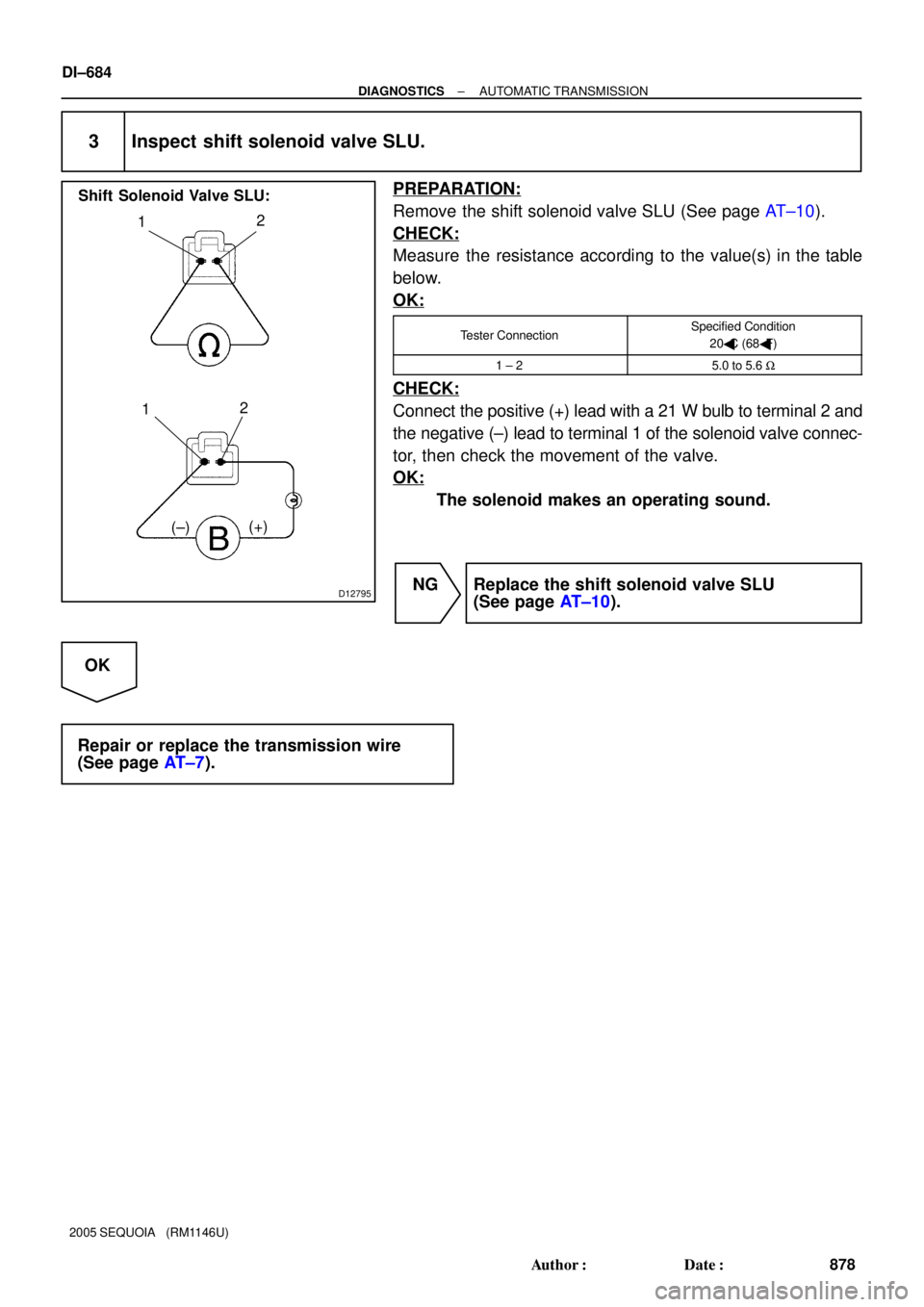
D12795
12
(±)(+)
12
Shift Solenoid Valve SLU:
DI±684
± DIAGNOSTICSAUTOMATIC TRANSMISSION
878 Author�: Date�:
2005 SEQUOIA (RM1146U)
3 Inspect shift solenoid valve SLU.
PREPARATION:
Remove the shift solenoid valve SLU (See page AT±10).
CHECK:
Measure the resistance according to the value(s) in the table
below.
OK:
Tester ConnectionSpecified Condition
20�C (68�F)
1 ± 25.0 to 5.6 W
CHECK:
Connect the positive (+) lead with a 21 W bulb to terminal 2 and
the negative (±) lead to terminal 1 of the solenoid valve connec-
tor, then check the movement of the valve.
OK:
The solenoid makes an operating sound.
NG Replace the shift solenoid valve SLU
(See page AT±10).
OK
Repair or replace the transmission wire
(See page AT±7).
Page 899 of 4323
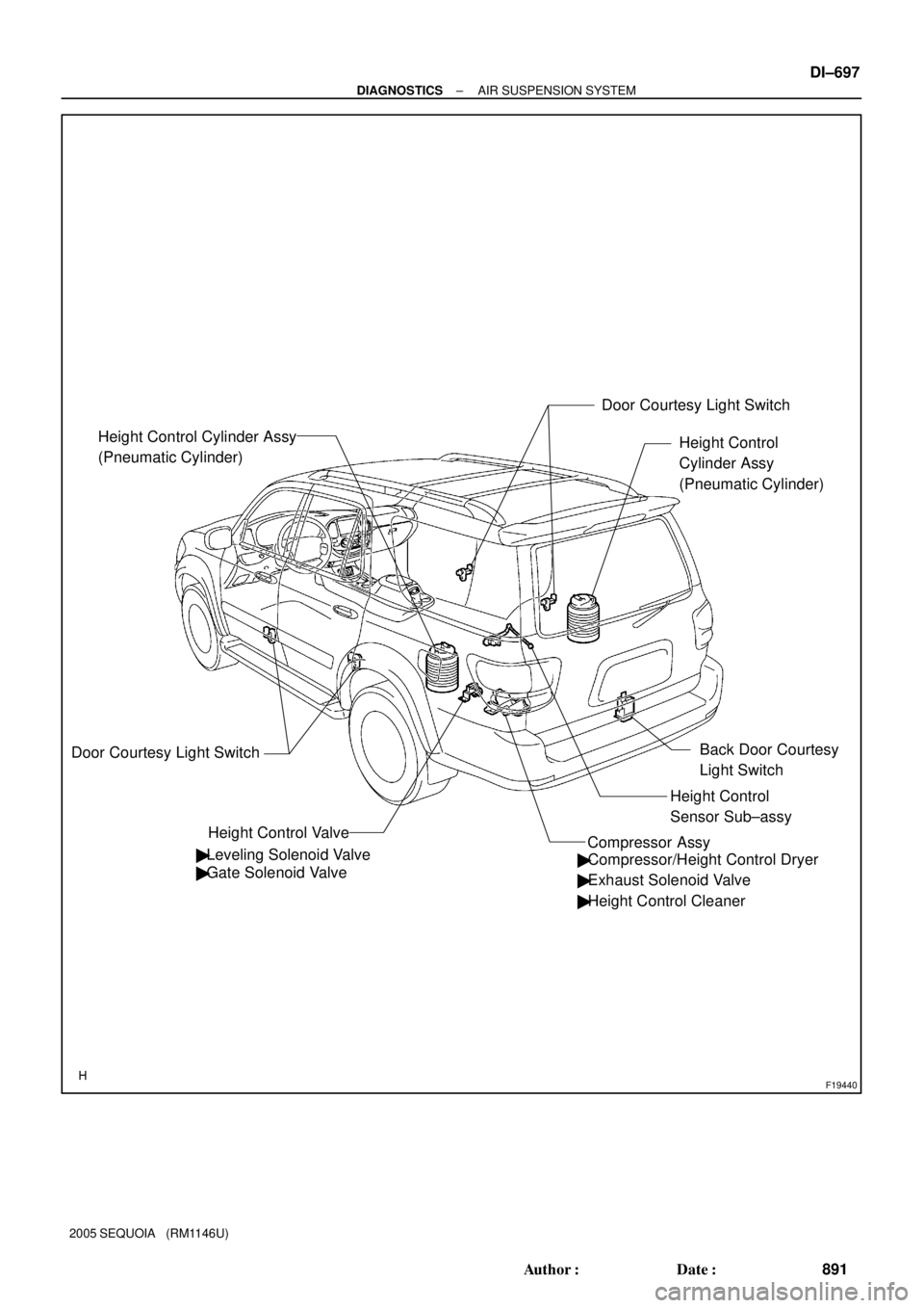
F19440
Height Control
Cylinder Assy
(Pneumatic Cylinder)
Height Control Valve Height Control Cylinder Assy
(Pneumatic Cylinder)
Door Courtesy Light Switch
� Leveling Solenoid Valve
� Gate Solenoid ValveDoor Courtesy Light Switch
� Compressor/Height Control Dryer
� Exhaust Solenoid Valve
� Height Control Cleaner
Height Control
Sensor Sub±assy
Compressor Assy
Back Door Courtesy
Light Switch
± DIAGNOSTICSAIR SUSPENSION SYSTEM
DI±697
891 Author�: Date�:
2005 SEQUOIA (RM1146U)
Page 900 of 4323
DIDCI±01
F19438
Height Control Sensor
Sub±assy
Height Control Mode
Select Switch
Body ECU
Stop Light Switch
Front Door Courtesy
Light Switch (Driver)
Front Door Courtesy
Light Switch
(Passenger)
Rear Door Courtesy
Light Switch (LH)
Rear Door Courtesy
Light Switch (RH)
Back Door Courtesy
Light SwitchCombination Meter
Leveling Solenoid Valve
AIR SUS Relay
DLC3
ECM
Translate ECU Compressor/
Height Control Dryer
Exhaust Solenoid Valve Height Control Valve
Compressor Assy Gate Solenoid Valve IG
BBAT
SBL2
SHRL
SGL2VN
HI
NR
LO
TD
UPSW
DWSW
Door
STPSLRR
SLRL
RC
RM+
RM±
SLEX
SIL
CANH
CANL
CANSuspension
Control ECU Height Control Switch
GND From IG SwitchFrom Battery
From
Battery DI±698
± DIAGNOSTICSAIR SUSPENSION SYSTEM
892 Author�: Date�:
2005 SEQUOIA (RM1146U)
SYSTEM DIAGRAM
Page 902 of 4323

DIDCN±01
F19465
: CAN
Compressor Assy
Combination Meter
Suspension
Control
ECU Exhaust Solenoid
Valve
Gate Solenoid Valve
Leveling Solenoid ValveAIR SUS Relay
Height Control Cylinder
(Pneumatic Cylinder)
Height Control Sensor
Sub±assy : ECU Output Signal
: ECU Input Signal
: Air Flow Path
Dryer
Height Control Cylinder
(Pneumatic Cylinder)� Speed Sensors
� Engine Speed
� L4 Switch
� Shift Position
Information
� Transmission
Model Informa-
tion
� Height Control Mode Select
Switch
� Height Control Switch
� Courtesy Light Switches
� Stop Light SwitchHI
N
LO
MAN. DI±700
± DIAGNOSTICSAIR SUSPENSION SYSTEM
894 Author�: Date�:
2005 SEQUOIA (RM1146U)
SYSTEM DESCRIPTION
1. GENERAL
�This system uses pneumatic cylinders instead of the coil springs that are used in a conventional rear
suspension. The suspension control ECU analyzes the information based on the switches, sensors,
and input signals, operates the compressor assy, and uses the solenoid valves to control the vehicle
height.
�The suspension control ECU detects, via the height control sensor, the changes in the rear vehicle
height that results from the number of occupants or the amount of the load. Then, the suspension con-
trol ECU controls the height control solenoid valves and the compressor assy in order to automatically
adjust the rear vehicle height to a constant (normal) vehicle height.
�Furthermore, three vehicle heights can be selected by operating the height control switch: HI, NOR-
MAL, and LO. The HI vehicle height ensures the vehicle's drive±through performance on rough roads.
The LO vehicle height facilitates the entry and exit of the occupants and the loading and unloading
of cargo. The NORMAL vehicle height helps realize excellent controllability and riding comfort during
normal driving.
Page 904 of 4323

3. FUNCTION OF MAIN COMPONENTS
ComponentOutline
Height Control Mode Select Switch�Used to select vehicle height")
DI±702
± DIAGNOSTICSAIR SUSPENSION SYSTEM
896 Author�: Date�:
2005 SEQUOIA (RM1146U)
3. FUNCTION OF MAIN COMPONENTS
ComponentOutline
Height Control Mode Select Switch�Used to select vehicle height control mode (Auto/Manual).
�Used to operate or stop auto leveling control.
Height Control Switch�Auto mode: Used to select vehicle height (HIGH, NORMAL, LOW).
�Manual mode: Used to select vehicle height optionally.
Height Control SensorConverts the vertical change of the rear axle, in proportion to the standard, to sig-
nals and detects vehicle height.
Height Control Indicator Lamp (Combination Meter)�Auto mode: Target vehicle height is displayed (HIGH, NORMAL, LOW).
�Manual mode: Current vehicle height is displayed (HIGH, NORMAL, LOW).
Height Control Manual Indicator Lamp (Combination Meter)
�Comes on during manual mode.
�Blinks when the suspension control ECU detects a system malfunction.
�Blinks during test mode.
�Displays output DTC.
Stop light Switch�Detects braking condition.
�Used to clear DTCs.
Pneumatic Cylinder (Height Control Cylinder Assy)Supports the vehicle body and adjusts the vehicle height.
Height Control Compressor Assy (Compressor/Height Con-
trol Dryer)�The compressor generates compressed air that is necessary to raise vehicle
height and supplies it to the height control cylinder assy.
�The dryer removes moisture from the compressed air.
Exhaust Solenoid ValveDrains the air in the height control cylinder assy when vehicle height is lowered.
(Built into the height control compressor assy)
Leveling Solenoid ValveOpens or closes the passage between the height cylinder assy and height control
compressor assy.
Gate Solenoid ValveOpens or closes the passage between the right and left height control cylinder assy
(Built into the leveling solenoid valve).
Suspension Control ECU
�Estimates vehicle condition based on the signals from sensors and switches, and
outputs the control signals to the compressor and valves.
�Blinks the height control manual indicator light when a system malfunction is de-
tected.
Air Suspension RelaySupplies power to the height control compressor assy.
Door Courtesy Switch (Body ECU)Detects whether the 5 doors, including the back door, are opened or closed, and
sends the signals to the suspension control ECU.
ECMSends the engine speed signal, etc. to the suspension control ECU through CAN
communication.
Speed Sensor (Skid Control ECU)Sends the vehicle wheel speed signal, etc. to the suspension control ECU through
CAN communication via the translate ECU.
Page 905 of 4323
F19466
Compressor Motor Exhaust Solenoid
ValveDryer
Compressor Portion
± DIAGNOSTICSAIR SUSPENSION SYSTEM
DI±703
897 Author�: Date�:
2005 SEQUOIA (RM1146U)
4. CONSTRUCTION AND OPERATION OF MAIN COMPONENTS
Compressor Assy
�The compressor and motor are used to make the compressed air necessary for raising the vehicle
height.
�The exhaust solenoid valve is provided on the compressor assy. The exhaust solenoid valve dis-
charges compressed air from the pneumatic cylinders to the atmosphere in order to lower the vehicle.
�The dryer is used to eliminate the moisture in the compressed air made by the compressor and motor.
�To protect the battery, this compressor assy operates only when the engine is running.
Specification
MotorTypeDC
MotorRated Voltage12 V
Exhaust Solenoid ValveRated Voltage12 V
Exhaust Solenoid ValveOperating Voltage Range10 to 15 V
Exhaust Solenoid ValveResistance10 to 14 W
Page 907 of 4323
F19469
Gate Solenoid Valve
Leveling Solenoid Valve
± DIAGNOSTICSAIR SUSPENSION SYSTEM
DI±705
899 Author�: Date�:
2005 SEQUOIA (RM1146U)
Height Control Valve
The height control valve consists of a leveling solenoid valve, and gate solenoid valve.
Specification
Leveling Solenoid ValveRated Voltage12 V
Leveling Solenoid ValveOperating Voltage Range10 to 15 V
Leveling Solenoid ValveResistance10 to 14 W
Gate Solenoid ValveRated Voltage12 V
Gate Solenoid ValveOperating Voltage Range10 to 15 V
Gate Solenoid ValveResistance17.5 to 21.5 W
Page 918 of 4323

PROBLEM SYMPTOMS TABLE
HINT:
�If a normal system code is displayed during the DTC check but the probl")
DIDCZ±01
DI±716
± DIAGNOSTICSAIR SUSPENSION SYSTEM
910 Author�: Date�:
2005 SEQUOIA (RM1146U)
PROBLEM SYMPTOMS TABLE
HINT:
�If a normal system code is displayed during the DTC check but the problem still occurs, check the cir-
cuits for each problem symptom in the order given in the table below and proceed to the relevant trou-
bleshooting page.
�Inspect the fuse before inspecting the suspected areas as shown in the chart below.
�Inspect each malfunction circuit in numerical order for the corresponding symptom.
�If the malfunction still exists even after checking and confirming that all the circuits are normal, replace
the suspension control ECU.
SymptomSuspected AreaSee page
Vehicle height control function does not operate.
If the compressor remains on for an excessive period of
time or turns on and off repeatedly, the system control will
be halted for up to 70 minutes, after which the system will
return to normal operation.
1. Air tube is seized
2. Power source circuit
3. IG signal circuit
4. Crankshaft position sensor circuit
5. Height control mode select switch circuit
6. Height control switch circuit
7. Height control sensor circuit
8. Leveling solenoid valve circuit
9. Gate solenoid valve circuit
10.Exhaust solenoid valve circuit
11. AIR SUS relay circuit
12.Height control compressor circuit
13.Suspension control ECU
±
DI±761
DI±793
DI±210
DI±778
DI±774
DI±731
DI±740
DI±736
DI±744
DI±747
DI±752
IN±35
Illuminated position of height control indicator lamp does not
change by the height control switch operation.
1. Power source circuit
2. Crankshaft position sensor circuit
3. Height control mode select switch circuit
4. Height control switch circuit
5. Height control sensor circuit
6. Leveling solenoid valve circuit
7. Gate solenoid valve circuit
8. Exhaust solenoid valve circuit
9. AIR SUS relay circuit
10.Height control compressor circuit
11. Speed sensor circuit
12.CAN communication circuit
13.Suspension control ECUDI±763
DI±761
DI±793
DI±210
DI±778
DI±774
DI±731
DI±740
DI±736
DI±744
DI±783
DI±1065
IN±35
Hunting of vehicle height occurs.
1. Air leakage (Height control cylinder assy rear)
2. Height control sensor circuit
3. Suspension control ECUSA±156
DI±731
IN±35
Vehicle height control operates, but vehicle height is uneven.
1. Air leakage
2. Clogging of the air tube
3. Height control sensor link sub±assy
4. Height control sensor circuit
5. Gate solenoid valve circuit
6. Suspension control ECUSA±156
±
SA±156
DI±731
DI±736
IN±35
Vehicle height control operates, but vehicle height is high or
low (Vehicle height in NORMAL mode differs from the standard
value).1. Height control sensor link sub±assy
2. Height control sensor circuit
3. Suspension control ECUSA±156
DI±731
IN±35
When vehicle height control is adjusted, it stops at extremely high
or low position.1. Height control sensor circuit
2. Height control sensor link sub±assy
3. Suspension control ECUDI±731
SA±156
IN±35

Front Door Courtesy
Light Switch
(Passenger)")