Page 2367 of 4323

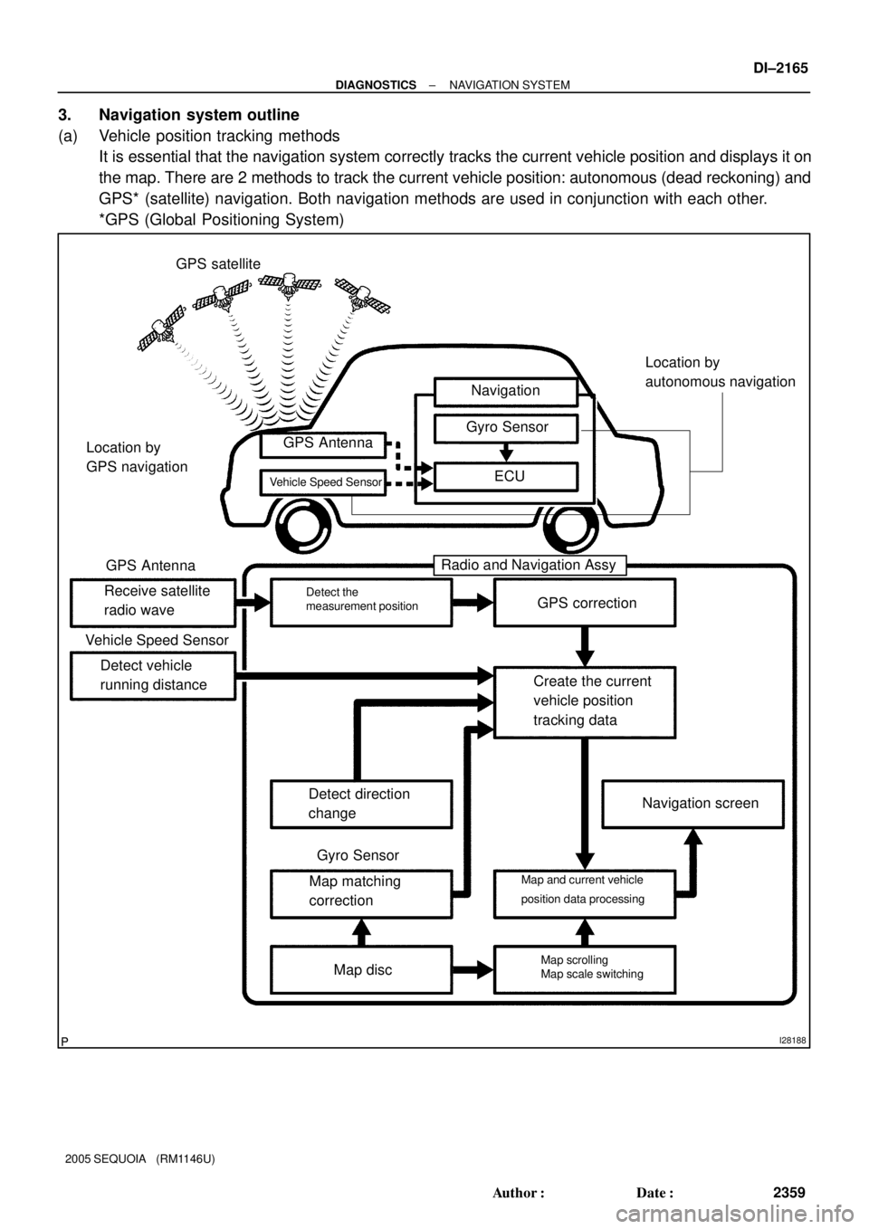
I28188
GPS satellite
Navigation
Gyro Sensor
ECU GPS Antenna
Receive satellite
radio waveGPS correction
Create the current
vehicle position
tracking data
Navigation screen
Map disc Map matching
correction Detect direction
change Detect vehicle
running distance
Radio and Navigation Assy
Detect the
measurement position
Map scrolling
Map scale switching Map and current vehicle
position data processing Vehicle Speed Sensor
GPS Antenna
Vehicle Speed SensorLocation by
GPS navigation
Gyro Sensor
Location by
autonomous navigation
± DIAGNOSTICSNAVIGATION SYSTEM
DI±2165
2359 Author�: Date�:
2005 SEQUOIA (RM1146U)
3. Navigation system outline
(a) Vehicle position tracking methods
It is essential that the navigation system correctly tracks the current vehicle position and displays it on
the map. There are 2 methods to track the current vehicle position: autonomous (dead reckoning) and
GPS* (satellite) navigation. Both navigation methods are used in conjunction with each other.
*GPS (Global Positioning System)
Page 2368 of 4323

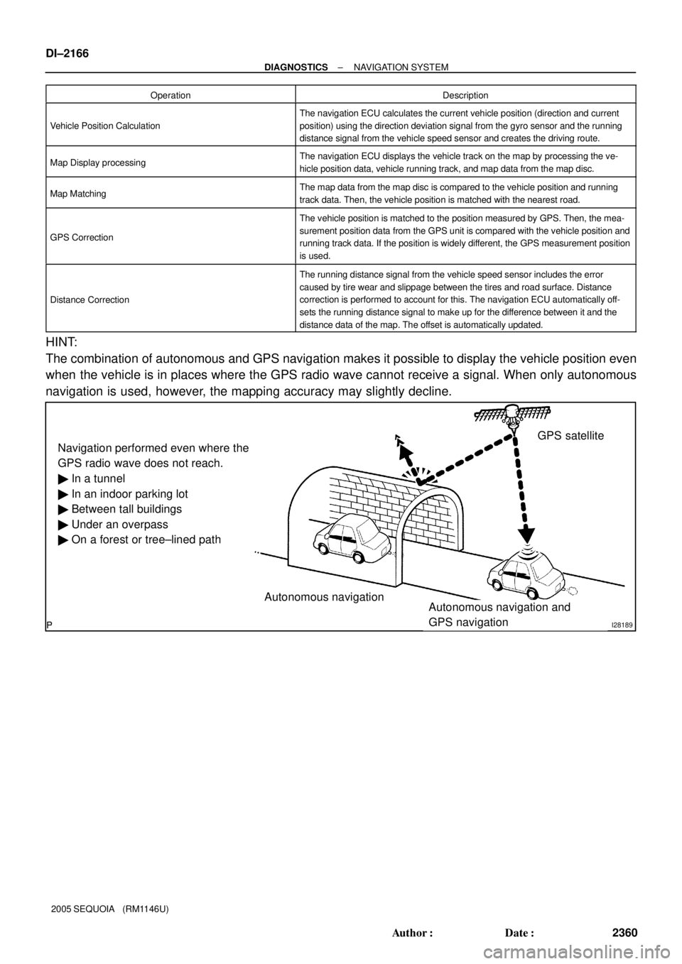
I28189
Navigation performed even where the
GPS radio wave does not reach.
� In a tunnel
� In an indoor parking lot
� Between tall buildings
� Under an overpass
� On a forest or tree±lined path
Autonomous navigation
Autonomous navigation and
GPS navigationGPS satellite DI±2166
± DIAGNOSTICSNAVIGATION SYSTEM
2360 Author�: Date�:
2005 SEQUOIA (RM1146U)Operation
Description
Vehicle Position Calculation
The navigation ECU calculates the current vehicle position (direction and current
position) using the direction deviation signal from the gyro sensor and the running
distance signal from the vehicle speed sensor and creates the driving route.
Map Display processingThe navigation ECU displays the vehicle track on the map by processing the ve-
hicle position data, vehicle running track, and map data from the map disc.
Map MatchingThe map data from the map disc is compared to the vehicle position and running
track data. Then, the vehicle position is matched with the nearest road.
GPS Correction
The vehicle position is matched to the position measured by GPS. Then, the mea-
surement position data from the GPS unit is compared with the vehicle position and
running track data. If the position is widely different, the GPS measurement position
is used.
Distance Correction
The running distance signal from the vehicle speed sensor includes the error
caused by tire wear and slippage between the tires and road surface. Distance
correction is performed to account for this. The navigation ECU automatically off-
sets the running distance signal to make up for the difference between it and the
distance data of the map. The offset is automatically updated.
HINT:
The combination of autonomous and GPS navigation makes it possible to display the vehicle position even
when the vehicle is in places where the GPS radio wave cannot receive a signal. When only autonomous
navigation is used, however, the mapping accuracy may slightly decline.
Page 2369 of 4323

I28190
GPS Current longitude/latitude/altitude is determined using the radio wave arrival time from four satellites.
± DIAGNOSTICSNAVIGATION SYSTEM
DI±2167
2361 Author�: Date�:
2005 SEQUOIA (RM1146U)
(b) Autonomous navigation
This method determines the relative vehicle position based on the running track determined by the
gyro and vehicle speed sensors located in the navigation ECU.
(1) Gyro sensor
Calculates the direction by detecting angular velocity. It is located in the radio and navigation
assy.
(2) Vehicle speed sensor
Used to calculate the vehicle running distance.
(c) GPS navigation (Satellite navigation)
This method detects the absolute vehicle position using radio wave from a GPS satellite.
* GPS satellites were launched by the U.S. Department of Defence for military purposes.
Number of satellitesMeasurementDescription
2 or lessMeasurement impossibleVehicle position cannot be obtained because the number of satellites is not enough.
32±dimensional measure-
ment is possibleVehicle position is obtained based on the current longitude and latitude (This is less precise
than 3±dimensional measurement).
43±dimensional measure-
ment is possibleVehicle position is obtained based on the current longitude, latitude and altitude.
Page 2371 of 4323

± DIAGNOSTICSNAVIGATION SYSTEM
DI±2169
2363 Author�: Date�:
2005 SEQUOIA (RM1146U)
4. DVD (Digital Versatile Disc) player outline (for navigation map)
The navigation ECU uses a laser pickup to read the digital signals recorded on a DVD.
HINT:
�Do not disassemble any part of the navigation system.
�Do not apply oil to the navigation system.
�Do not insert anything but a DVD into the navigation system.
CAUTION:
Because the navigation system uses an invisible laser beam, do not look directly at the laser pickup.
Be sure to only operate the navigation as instructed.
5. CD (Compact Disc) player outline
A CD player uses a laser pickup to read digital signals recorded on a CD. By converting the digital signals
to analog, it can play music and other things. In general, CD players can play a 4.7±inch (12 cm) or 3.2±inch
(8 cm) disc.
HINT:
�Do not disassemble any part of the CD player.
�Do not apply oil to the CD player.
�Do not insert anything but a CD into the CD player.
CAUTION:
Because the CD player uses an invisible laser beam, do not look directly at the laser pickup. Be sure
to only operate the player as instructed.
Page 2382 of 4323
DIDBZ±01
I28227
I28228
I28229
DI±2180
± DIAGNOSTICSNAVIGATION SYSTEM
2374 Author�: Date�:
2005 SEQUOIA (RM1146U)
NAVIGATION CHECK MODE (GPS Information)
HINT:
�This mode displays GPS satellite information.
�Illustrations may differ from the actual vehicle depending on the device settings and options. There-
fore, some detailed areas may not be shown exactly the same as on the actual vehicle.
1. Enter diagnostic mode (See page DI±2191).
2. Select ºNavigation Checkº from the ºDiagnosis
MENUº screen.
3. Select ºGPS Informationº from the ºNavigation
Checkº screen.
4. When GPS information is displayed, check the GPS
conditions.
HINT:
This screen is updated once per second when input signals to
the vehicle are changed.
Page 2398 of 4323

I28242
I28243
*2
*3*2
*5
*4
*1 *1
DI±2196
± DIAGNOSTICSNAVIGATION SYSTEM
2390 Author�: Date�:
2005 SEQUOIA (RM1146U)
(c) NAVIGATION CHECK
(1) Navigation Check Screen
HINT:
Each item is grayed out or not displayed based on the device settings.
(2) GPS information Screen
Satellite information/*1
(3) Information from a maximum of 12 satellites is displayed on the screen. This information includes
the target GPS satellite number, elevation angle, direction and signal level.
Receiving condition/*2
(DENSO model)
DisplayContents
TThe system is receiving a GPS signal, but is not using it for location.
PThe system is using the GPS signal for location.
±The system cannot receive a GPS signal.
(AISIN AW model)
DisplayContents
01HThe system cannot receive a GPS signal.
02HThe system is tracing a satellite.
03HThe system is receiving a GPS signal, but is not using it for location.
04HThe system is using the GPS signal for location.
Measurement information/*3
DisplayContents
2D2±dimensional location method is being used.
3D3±dimensional location method is being used.
NGLocation data cannot be used.
ErrorReception error has occurred.
±Any other state.
Page 2415 of 4323
DIDC8±01
± DIAGNOSTICSNAVIGATION SYSTEM
DI±2213
2407 Author�: Date�:
2005 SEQUOIA (RM1146U)
CIRCUIT INSPECTION
Pressing power switch does not turn on system
INSPECTION PROCEDURE
1 Check cabin.
CHECK:
Check that conditions in the cabin are not likely to cause condensation.
HINT:
This problem occurs when the cabin is humid and the temperature rapidly changes. This condition may pro-
duce condensation, resulting in a short circuit.
OK:
Condensation is not likely.
NG Dry cabin and recheck conditions.
OK
Proceed to next circuit inspection shown in problem symptoms table (See page DI±2184).
Page 2417 of 4323
± DIAGNOSTICSNAVIGATION SYSTEM
DI±2215
2409 Author�: Date�:
2005 SEQUOIA (RM1146U)
3 Check cabin.
CHECK:
Check if condensation is likely to occur, or the temperature is high or low (extremely cold) in the cabin.
HINT:
This problem occurs when the cabin is humid and the temperature rapidly changes. This condition may pro-
duce condensation, resulting in a short circuit.
OK:
The above conditions are not observed.
NG Set cabin temperature to appropriate degrees
(20 to 30�C) (68 to 86�F).
OK
Proceed to next circuit inspection shown in problem symptoms table (See page DI±2184).