Page 383 of 1943

CHASSIS ± BRAKES
182CH61
Reservoir Tank
Pump Motor
Pressure Switches
Relief
Valve
Master Cylinder
Pressure
SensorPressure Sensor
SLRSLA
OFF
Stroke Simulator
SS
OFF
Reservoir
Pressure
Sensor
Pressure
Sensor
SRrR
OFF
P & B Valve
Rear Wheel Cylinders Front Wheel CylindersOFF
SMC2 SMC1
SRrH
OFFSFRH
OFF
SFRR
OFFSFLH
OFF
SFLR
OFF
OFF OFF
Accumulator121
3) Fail-Safe Control
If a malfunction occurs in the brake ECU, in the input signals from the sensors, or in the actuator system,
this function prohibits the current from flowing to the brake actuator.
As a result, the solenoids in the brake actuator turn off, enabling the braking force of the hydraulic brake
to take effect. The relief function is provided in order to ensure the proper wheel cylinder hydraulic pres-
sure even if the linear solenoid valve SLA is OFF (closed). Only if the regenerative brake system cannot
be used, such as in the case of a malfunction in the communication with the HV ECU, this function
switches controls to enable the hydraulic brake to generate the entire brake force.
Page 509 of 1943
± MAINTENANCEINSIDE VEHICLE
MA±3
56 Author�: Date�:
2001 PRIUS (RM778U)
13. ACCELERATOR PEDAL
Check the pedal for smooth operation and uneven pedal effort or catching.
14. BRAKE PEDAL (See page BR±7)
(a) Check the pedal for smooth operation.
(b) Check that the pedal has the proper reserve distance and freeplay.
15. BRAKES
At a safe place, check that the brakes do not pull to one side when applied.
16. PARKING BRAKE (See page BR±9)
(a) Check that the pedal has the proper travel.
(b) On a safe incline, check that the vehicle is held securely with only the parking brake applied.
17. TRANSAXLE ºPARKº MECHANISM
(a) Check the lock release button of the selector lever for proper and smooth operation.
(b) On a safe incline, check that the vehicle is held securely with the selector lever in ºPº position and all
brakes released.
Page 1659 of 1943

SA1ZR±01
F08617
R14731
Backlash:Deviation:
F12940SST
± SUSPENSION AND AXLEFRONT AXLE HUB
SA±9
2001 PRIUS (RM778U)
REMOVAL
1. REMOVE FRONT WHEEL
Torque: 103 N´m (1,050 kgf´cm, 76 ft´lbf)
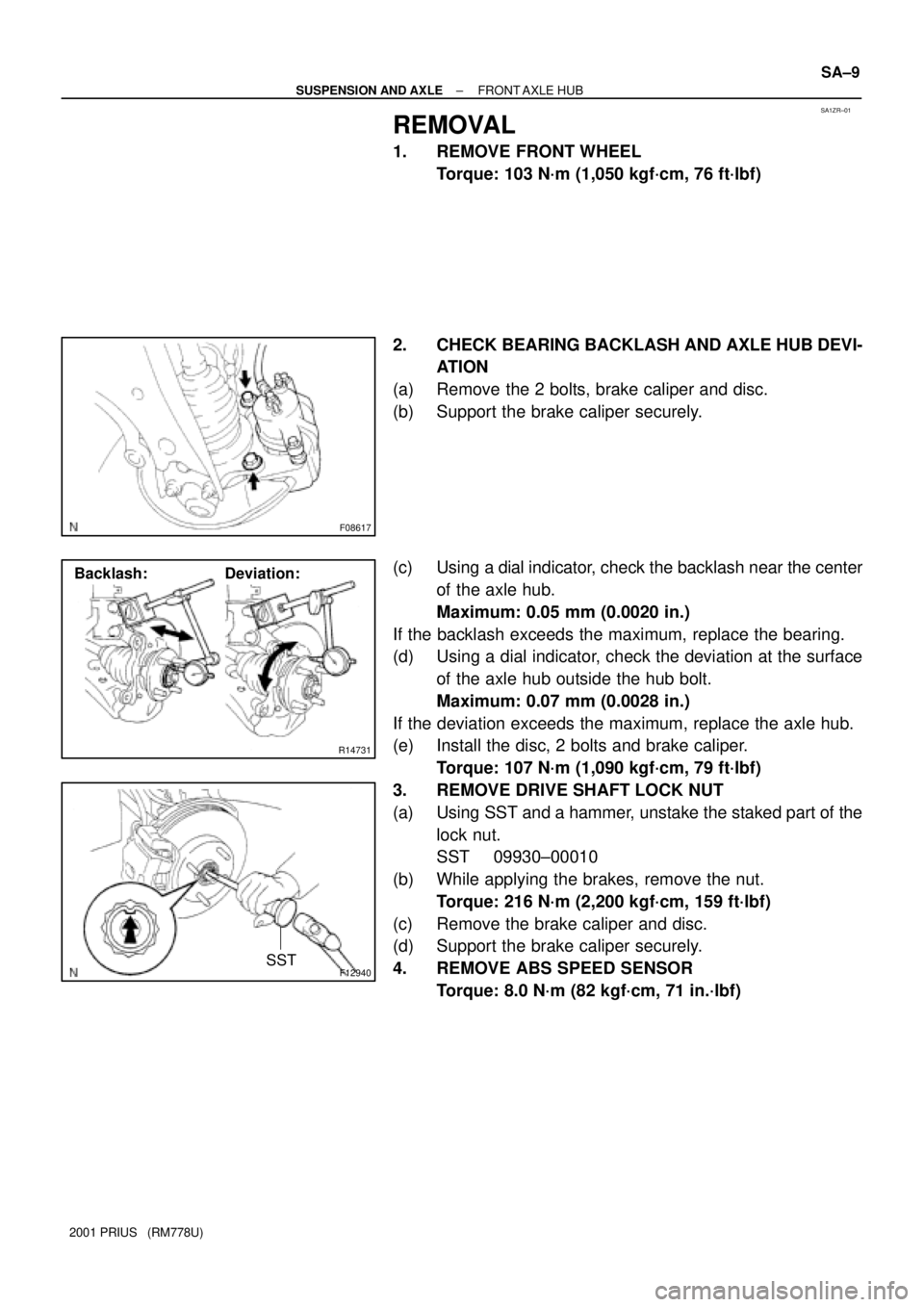
2. CHECK BEARING BACKLASH AND AXLE HUB DEVI-
ATION
(a) Remove the 2 bolts, brake caliper and disc.
(b) Support the brake caliper securely.
(c) Using a dial indicator, check the backlash near the center
of the axle hub.
Maximum: 0.05 mm (0.0020 in.)
If the backlash exceeds the maximum, replace the bearing.
(d) Using a dial indicator, check the deviation at the surface
of the axle hub outside the hub bolt.
Maximum: 0.07 mm (0.0028 in.)
If the deviation exceeds the maximum, replace the axle hub.
(e) Install the disc, 2 bolts and brake caliper.
Torque: 107 N´m (1,090 kgf´cm, 79 ft´lbf)
3. REMOVE DRIVE SHAFT LOCK NUT
(a) Using SST and a hammer, unstake the staked part of the
lock nut.
SST 09930±00010
(b) While applying the brakes, remove the nut.
Torque: 216 N´m (2,200 kgf´cm, 159 ft´lbf)
(c) Remove the brake caliper and disc.
(d) Support the brake caliper securely.
4. REMOVE ABS SPEED SENSOR
Torque: 8.0 N´m (82 kgf´cm, 71 in.´lbf)
Page 1663 of 1943

SA20B±01
FA1535
SST
F12940SST
F11576
SST
± SUSPENSION AND AXLEFRONT DRIVE SHAFT
SA±17
2001 PRIUS (RM778U)
REMOVAL
NOTICE:
�The hub bearing could be damaged if it is subjected
to the vehicle weight, such as when moving the ve-
hicle with the drive shaft removed.
Therefore, if it is absolutely necessary to place the ve-
hicle weight on the hub bearing, first support it with
the SST.
SST 09608±16042 (09608±02021, 09608±02041)
�After disconnecting the drive shaft from the axle hub,
work carefully so as not to damage the ABS speed
sensor rotor serrations on the drive shaft.
1. REMOVE FRONT WHEEL
Torque: 103 N´m (1,050 kgf´cm, 76 ft´lbf)
2. REMOVE ENGINE UNDER COVER
3. DRAIN ATF
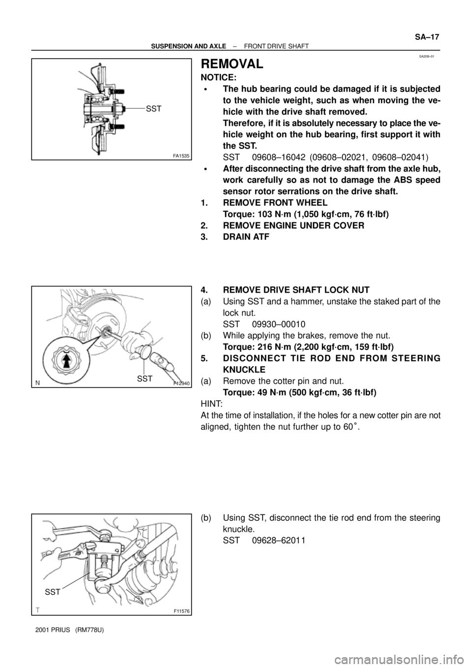
4. REMOVE DRIVE SHAFT LOCK NUT
(a) Using SST and a hammer, unstake the staked part of the
lock nut.
SST 09930±00010
(b) While applying the brakes, remove the nut.
Torque: 216 N´m (2,200 kgf´cm, 159 ft´lbf)
5. DISCONNECT TIE ROD END FROM STEERING
KNUCKLE
(a) Remove the cotter pin and nut.
Torque: 49 N´m (500 kgf´cm, 36 ft´lbf)
HINT:
At the time of installation, if the holes for a new cotter pin are not
aligned, tighten the nut further up to 60°.
(b) Using SST, disconnect the tie rod end from the steering
knuckle.
SST 09628±62011
Page 1678 of 1943

± BRAKETROUBLESHOOTING
BR±3
1518 Author�: Date�:
2001 PRIUS (RM778U) Noise from brakes
1. Pad or lining (Cracked or distorted)
2. Installation bolt (Loose)
3. Disc or drum (Scored)
4. Pad support plate (Loose)
5. Sliding pin (Worn)
6. Pad or lining (Dirty)
7. Pad or lining (Glazed)
8. Tension or return spring (Faulty)
9. Anti±squeal shim (Damaged)
10.Shoe hold±down spring (Damaged)BR±23
BR±32
BR±26
BR±26
BR±32
BR±23
BR±26
BR±23
BR±32
BR±23
BR±32
BR±32
BR±23
BR±32
Brake warning light lights up*1
(Parking brake pedal released)
1. Brake fluid level
2. Hydraulic brake booster power supply system (Faulty)
BR±41
Brake warning light lights up and brake warning buzzer sounds*2Hydraulic brake booster power supply system (Faulty)BR±41
ABS warning light lights up*31. Anti±lock brake system (Faulty)
2. Hydraulic brake booster power supply system (Faulty)
BR±41
*1, *3: The light may stay on for about 60 seconds after the engine has been started. It is normal if it goes
out after a while.
*
2, *3: Depressing the brake pedal repeatedly may turn on the warning light and buzzer. It is normal if the
light goes out and the buzzer stops sounding after a few seconds.
Page 1895 of 1943

BO3T5±01
BO0632
BO0633
45° 15° BO±88
± BODYSEAT BELT
2001 PRIUS (RM778U)
INSPECTION
CAUTION:
Replace the seat belt assembly (outer belt, inner belt, bolts,
nuts or sill±bar) if it has been used in a severe impact. The
entire assembly should be replaced even if damage is not
obvious.
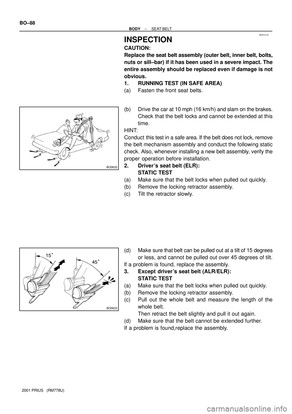
1. RUNNING TEST (IN SAFE AREA)
(a) Fasten the front seat belts.
(b) Drive the car at 10 mph (16 km/h) and slam on the brakes.
Check that the belt locks and cannot be extended at this
time.
HINT:
Conduct this test in a safe area. If the belt does not lock, remove
the belt mechanism assembly and conduct the following static
check. Also, whenever installing a new belt assembly, verify the
proper operation before installation.
2. Driver 's seat belt (ELR):
STATIC TEST
(a) Make sure that the belt locks when pulled out quickly.
(b) Remove the locking retractor assembly.
(c) Tilt the retractor slowly.
(d) Make sure that belt can be pulled out at a tilt of 15 degrees
or less, and cannot be pulled out over 45 degrees of tilt.
lf a problem is found, replace the assembly.
3. Except driver's seat belt (ALR/ELR):
STATIC TEST
(a) Make sure that the belt locks when pulled out quickly.
(b) Remove the locking retractor assembly.
(c) Pull out the whole belt and measure the length of the
whole belt.
Then retract the belt slightly and pull it out again.
(d) Make sure that the belt cannot be extended further.
If a problem is found,replace the assembly.