Page 1707 of 1943

INSTALLATION
1. INSTALL MAIN SHAFT LOWER DUST SEAL
(a) Install the main shaft lower dust seal with t")
SR1BJ±01
F12215
F12214
Matchmarks
A
B SR±14
± STEERINGTILT STEERING COLUMN
2001 PRIUS (RM778U)
INSTALLATION
1. INSTALL MAIN SHAFT LOWER DUST SEAL
(a) Install the main shaft lower dust seal with the 3 nuts.
Torque: 4.9 N´m (50 kgf´cm, 43 in.´lbf)
(b) Connect the accelerator pedal with the 2 bolts.
(c) Install the parking brake cable bracket with the 2 nuts.
2. INSTALL COLUMN HOLE COVER
3. INSTALL SLIDING YOKE
Install the sliding yoke to the main shaft assembly with the bolt.
Torque: 35 N´m (360 kgf´cm, 26 ft´lbf)
4. INSTALL NO. 2 INTERMEDIATE SHAFT ASSEMBLY
Temporarily install the No. 2 intermediate shaft assembly to the
sliding yoke with the bolt.
5. INSTALL STEERING COLUMN ASSEMBLY
(a) Install the steering column assembly with the 2 bolts and
2 nuts.
Torque: 25 N´m (260 kgf´cm, 19 ft´lbf)
(b) Connect the connectors.
6. INSTALL INSTRUMENT FINISH PANEL
Install the instrument finish panel with the 3 screws.
7. CONNECT NO. 2 INTERMEDIATE SHAFT ASSEMBLY
(a) Align the matchmarks on the No. 2 intermediate shaft as-
sembly and control valve shaft.
(b) Install the bolt ºBº and torque the bolt ºAº.
Torque: 35 N´m (360 kgf´cm, 26 ft´lbf)
8. INSTALL SHIFT LOCK COMPUTER SUB±ASSEMBLY
Install the shift lock computer sub±assembly with the screw.
9. CONNECT COLUMN HOLE COVER
Connect the column hole cover with the 3 clips.
10. INSTALL SHIFT LEVER ASSEMBLY
(See page HT±52)
Page 1708 of 1943

11. CONNECT TRANSMISSION CONTROL CABLE
12. INSTALL SPIRAL CABLE (See page BE±19)
13. INSTALL COMBINATION SWITCH WITH S")
F12830
F08459
Marks
± STEERINGTILT STEERING COLUMN
SR±15
2001 PRIUS (RM778U)
11. CONNECT TRANSMISSION CONTROL CABLE
12. INSTALL SPIRAL CABLE (See page BE±19)
13. INSTALL COMBINATION SWITCH WITH SPIRAL
CABLE
(a) Install the combination switch with spiral cable with the 3
screws.
(b) Connect the airbag connector.
(c) Connect the connectors.
14. INSTALL UPPER AND LOWER COLUMN COVERS
(a) Install the upper column cover with the screw.
(b) Install the lower column cover with the 3 screws.
15. INSTALL LOWER INSTRUMENT FINISH PANEL
(a) Connect the connectors and DLC3 and install the lower
instrument finish panel.
(b) Install the screw and bolt.
(c) Connect the hood lock release lever with the 2 screws.
16. CENTER SPIRAL CABLE
(a) Check that the front wheels are facing straight ahead.
(b) Turn the cable counterclockwise by hand until it becomes
harder to turn.
(c) Then rotate the cable clockwise about 2.5 turns to align
the marks.
HINT:
The cable will rotate about 2.5 turns to either left or right of the
center.
17. INSTALL STEERING WHEEL
(a) Align the matchmarks on the steering wheel and main
shaft assembly.
(b) Install the steering wheel set nut.
Torque: 50 N´m (510 kgf´cm, 37 ft´lbf)
18. INSTALL STEERING WHEEL PAD
NOTICE:
�Never use airbag parts from another vehicle. When
replacing parts, replace with new ones.
�Make sure the wheel pad is installed with the speci-
fied torque.
�If the wheel pad has been dropped, or there are
cracks, dents or other defects in the case or connec-
tor, replace the wheel pad with a new one.
�When installing the wheel pad, take care that the wir-
ings do not interfere with other parts and that they are
not pinched between other parts.
(a) Connect the connector.
(b) Connect the airbag connector.
Page 1726 of 1943

Z14034
Fig.1
Fig.2Power Source
Safing
Sensor
Squibs
Deceleration Sensor
H01581
Outer
H01582
Lock of connector is released
Disconnection is completed
± SUPPLEMENTAL RESTRAINT SYSTEMSRS AIRBAG
RS±7
2001 PRIUS (RM778U)
(b) When the vehicle is involved in a frontal collision in the
hatched area (Fig. 1) and the shock is larger than the pre-
determined level, the SRS is activated automatically. A
safing sensor is designed to go on at a smaller decelera-
tion rate than the airbag sensor. As illustrated in Fig. 2,
ignition is caused when current flows to the squib, which
happens when a safing sensor and the deceleration sen-
sor go on simultaneously. When a deceleration force acts
on the sensors, 2 squibs in the driver airbag and front pas-
senger airbag ignite and generate gas. The gas discharg-
ing into the driver airbag and front passenger airbag rap-
idly increases the pressure inside the bags, breaking
open the steering wheel pad and instrument panel.
Bag inflation then ends, and the bags deflate as the gas
is discharged through discharge holes at the bag's rear or
side.
11. DISCONNECTION OF CONNECTORS FOR FRONT
AIRBAG SENSOR AND SIDE AIRBAG SENSOR
(a) While holding both flank sides of the outer, slide the outer
to the direction shown by an arrow.
(b) Lock of the connectors is released, then disconnect the
connectors.
HINT:
Be sure to hold both flank sides of the outer. If holding the top
and bottom sides, it will obstruct disconnection.
Page 1741 of 1943

INSPECTION
1. Vehicles not involved in collision:
INSPECT SUPPLEMENTAL RESTRAINT")
RS0R5±01
H15507
H15709
RS±28
± SUPPLEMENTAL RESTRAINT SYSTEMFRONT PASSENGER AIRBAG ASSEMBLY
2001 PRIUS (RM778U)
INSPECTION
1. Vehicles not involved in collision:
INSPECT SUPPLEMENTAL RESTRAINT SYSTEM
(a) Do a diagnostic system check (See page DI±497).
(b) Do a visual check which includes the following item with
the front passenger airbag assembly installed in the ve-
hicle.
Check cuts, minute cracks or marked discoloration on the
front passenger airbag assembly and instrument panel.
2. Vehicle involved in a collision and airbag is not
deployed:
INSPECT SUPPLEMENTAL RESTRAINT SYSTEM
(a) Do a diagnostic system check (See page DI±497).
(b) Do a visual check which includes the following items with
the front passenger airbag assembly removed from the
vehicle.
�Check cuts, minute cracks or marked discoloration
on the front passenger airbag assembly.
�Check cuts and cracks in wire harness, and for chip-
ping in connectors.
�Check the deformation or cracks on the instrument
panel and instrument panel reinforcement.
CAUTION:
For removal and installation of the front passenger airbag
assembly, see page RS±27 and RS±38, and be sure to fol-
low the correct procedure.
HINT:
If the instrument panel or instrument panel reinforcement is de-
formed or cracked, never repair it. Always replace it with a new
one.
3. Vehicle involved in a collision and airbag is deployed:
INSPECT SUPPLEMENTAL RESTRAINT SYSTEM
(a) Do a diagnostic system check (See page DI±497).
(b) Do a visual check which includes the following items with
the front passenger airbag assembly removed from the
vehicle.
�Check the deformation or cracks on the instrument
panel and instrument panel reinforcement.
�Check the damage on the connector and wire har-
ness.
Page 1742 of 1943
± SUPPLEMENTAL RESTRAINT SYSTEMFRONT PASSENGER AIRBAG ASSEMBLY
RS±29
2001 PRIUS (RM778U)
CAUTION:
For removal and installation of the front passenger airbag
assembly, see page SR±6 and SR±14, and be sure to follow
the correct procedure.
HINT:
If the instrument panel or instrument panel reinforcement is de-
formed or cracked, never repair it. Always replace it with a new
one.
Page 1749 of 1943
RS±36
± SUPPLEMENTAL RESTRAINT SYSTEMFRONT PASSENGER AIRBAG ASSEMBLY
2001 PRIUS (RM778U)
CAUTION:
�The front passenger airbag assembly is very hot
when the airbag is deployed, so leave it alone for at
least 30 minutes after deployment.
�Use gloves and safety glasses when handling a front
passenger airbag assembly with the deployed airbag.
�Always wash your hands with water after completing
the operation.
�Do not apply water, etc. to a front passenger airbag
assembly with the deployed airbag.
(1) Remove the front passenger airbag assembly from
the instrument panel (See page RS±27).
(2) Place the front passenger airbag assembly in a vi-
nyl bag, tie the end tightly and dispose of it in the
same way so as other general parts disposal.
Page 1769 of 1943
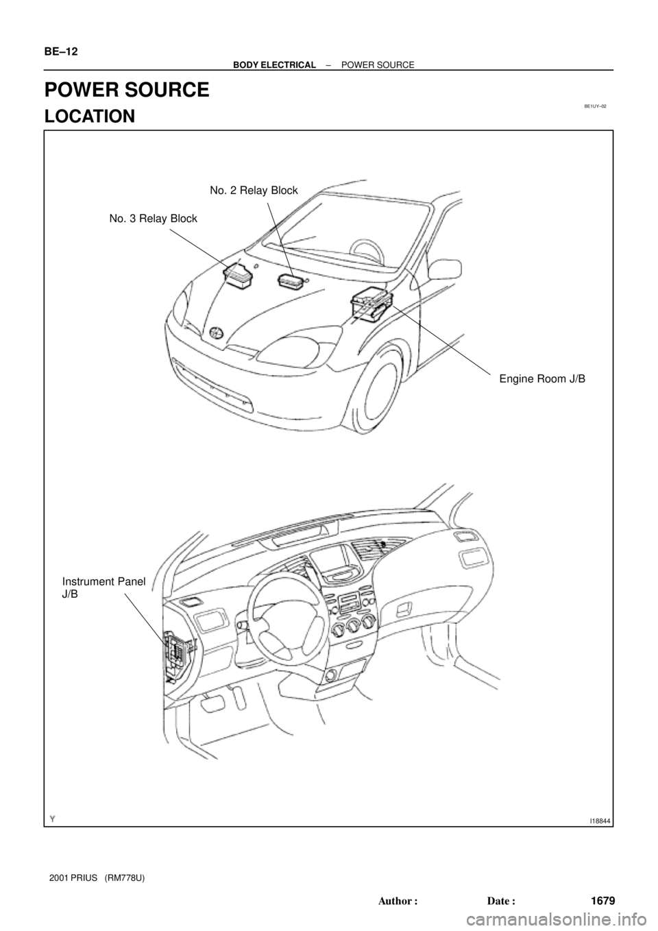
BE1UY±02
I18844
Engine Room J/B No. 2 Relay Block
Instrument Panel
J/B
No. 3 Relay Block BE±12
± BODY ELECTRICALPOWER SOURCE
1679 Author�: Date�:
2001 PRIUS (RM778U)
POWER SOURCE
LOCATION
Page 1771 of 1943
I17788
Instrument Panel J/B:
Fuses: Relays:
A. IG1 Relay
B. ACC Relay
C. TAIL Relay
D. POWER Relay
E. DEF Relay
1
2
3
4
5
6
7
8
9
10
11
12
13
14
15 A
B C
D
16
E
1. HTR Fuse
2. STOP Fuse
3. ECU±B Fuse
4. DOOR Fuse
5. OBDII Fuse
6. PWR1 Fuse
7. AM1 Fuse8. GAUGE Fuse
9. ECU±IG Fuse
10. WIPER Fuse
11. WASHER Fuse
12. PANEL Fuse
13. TAIL Fuse
14. ACC Fuse15. CIG Fuse
16. SRS ACC Fuse
17. PWR Fuse
18 DEF Fuse
1718 BE±14
± BODY ELECTRICALPOWER SOURCE
1681 Author�: Date�:
2001 PRIUS (RM778U)

CAUTION:
For removal and installation of the front passenger airbag
assembly, see page SR±6 and SR±14, an")