Page 676 of 1943
A00406
KNK signal waveform
0.5V/
Division
0V
0V5 m sec./Division
100
sec./Division 0.5V/
Division
± DIAGNOSTICSENGINE
DI±73
2001 PRIUS (RM778U)
4 Does malfunction disappear when a good knock sensor is installed?
YES Replace knock sensor.
NO
Check and replace ECM (See page IN±41).
Reference: INSPECTION USING OSCILLOSCOPE
�With the engine racing (4,000 rpm) measure between ter-
minal KNK of the ECM connector and body ground.
HINT:
The correct waveforms are as shown.
�Spread the time on the horizontal axis, and confirm that
period of the wave is 132 m sec.
(Normal mode vibration frequency of knock sensor:
8.1 kHz)
HINT:
If normal mode vibration frequency is not 8.1 kHz the sensor is
malfunctioning.
Page 678 of 1943

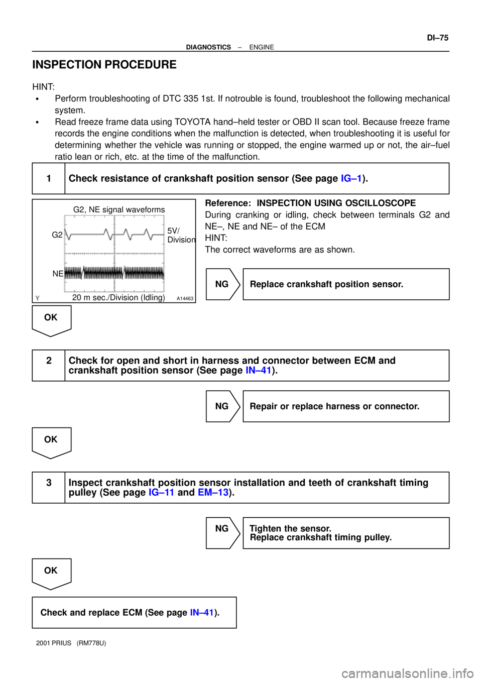
A14463
G2, NE signal waveforms
5V/
Division G2
NE
20 m sec./Division (Idling)
± DIAGNOSTICSENGINE
DI±75
2001 PRIUS (RM778U)
INSPECTION PROCEDURE
HINT:
�Perform troubleshooting of DTC 335 1st. If notrouble is found, troubleshoot the following mechanical
system.
�Read freeze frame data using TOYOTA hand±held tester or OBD II scan tool. Because freeze frame
records the engine conditions when the malfunction is detected, when troubleshooting it is useful for
determining whether the vehicle was running or stopped, the engine warmed up or not, the air±fuel
ratio lean or rich, etc. at the time of the malfunction.
1 Check resistance of crankshaft position sensor (See page IG±1).
Reference: INSPECTION USING OSCILLOSCOPE
During cranking or idling, check between terminals G2 and
NE±, NE and NE± of the ECM
HINT:
The correct waveforms are as shown.
NG Replace crankshaft position sensor.
OK
2 Check for open and short in harness and connector between ECM and
crankshaft position sensor (See page IN±41).
NG Repair or replace harness or connector.
OK
3 Inspect crankshaft position sensor installation and teeth of crankshaft timing
pulley (See page IG±11 and EM±13).
NG Tighten the sensor.
Replace crankshaft timing pulley.
OK
Check and replace ECM (See page IN±41).
Page 679 of 1943

DI±76
± DIAGNOSTICSENGINE
2001 PRIUS (RM778U)
DTC P0340 Camshaft Position Sensor Circuit
Malfunction
CIRCUIT DESCRIPTION
Camshaft position sensor (G22 signal) consist of signal plate and pick up coil.
The G22 signal plate has one tooth on its outer circumference and is mounted on the exhaust camshaft.
When the camshafts rotate, the protrusion on the signal plate and the air gap on the pick up coil change,
causing fluctuations in the magnetic field and generating an electromotive force in the pick up coil.
The NE signal plate has 34 teeth and is mounted on the crankshaft. The NE signal sensor generates 34
signals for every engine revolution. The ECM detects the standard crankshaft angle based on the G22 sig-
nals and the actual crankshaft angle and the engine speed by the NE signals.
DTC No.DTC Detecting ConditionTrouble Area
P0340
No camshaft position sensor signal to ECM during cranking.
(2 trip detection logic)�Open or short in camshaft position sensor circuit
�Camshaft position sensor
P0340No camshaft position sensor signal to ECM with engine speed
600 rpm or more
�Camshaft osition sensor
�Camshaft timing pulley
�ECM
WIRING DIAGRAM
Refer to DTC P0335 on page DI±74.
INSPECTION PROCEDURE
HINT:
Read freeze frame data using TOYOTA hand±held tester or OBD II scan tool. Because freeze frame records
the engine conditions when the malfunction is detected, when troubleshooting it is useful for determining
whether the vehicle was running or stopped, the engine warmed up or not, the air±fuel ratio lean or rich, etc.
at the time of the malfunction.
1 Check resistance of camshaft position sensor (Signal generator)
(See page IG±1).
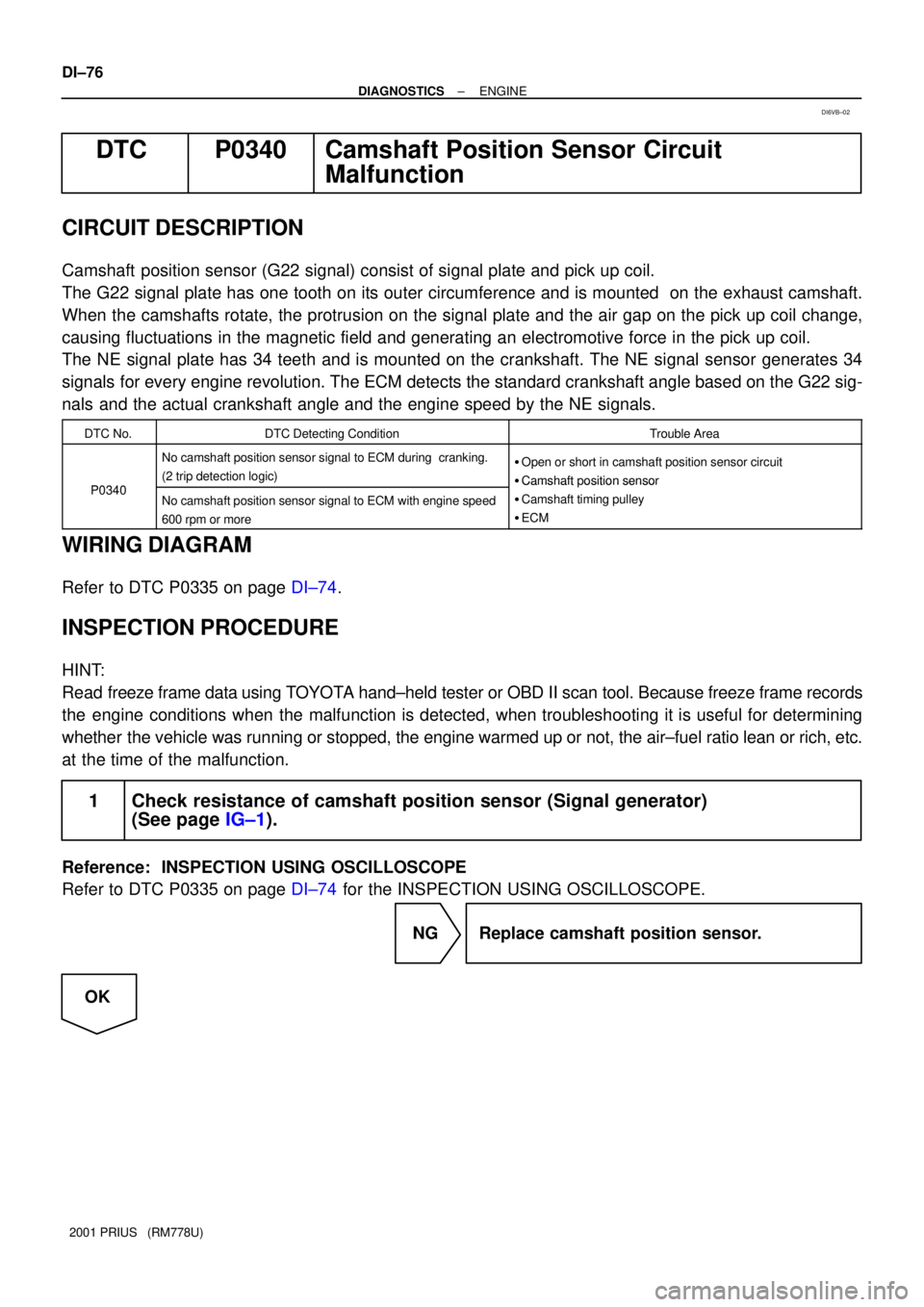
Reference: INSPECTION USING OSCILLOSCOPE
Refer to DTC P0335 on page DI±74 for the INSPECTION USING OSCILLOSCOPE.
NG Replace camshaft position sensor.
OK
DI6VB±02
Page 680 of 1943
± DIAGNOSTICSENGINE
DI±77
2001 PRIUS (RM778U)
2 Check for open and short in harness and connector between ECM and camshaft
position sensor (See page IN±41).
NG Repair or replace harness or connector.
OK
3 Inspect sensor installation and tooth of camshaft timing pulley
(See page EM±15).
NG Tighten the sensor.
Replace camshaft timing pulley.
OK
Check and replace ECM (See page IN±41).
Page 681 of 1943

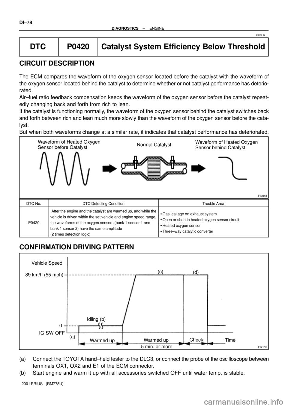
FI7081
Waveform of Heated Oxygen
Sensor before CatalystNormal CatalystWaveform of Heated Oxygen
Sensor behind Catalyst
FI7132
Vehicle Speed
0
IG SW OFF
Warmed upWarmed upCheck
Time (a)(c)
(d)
Idling (b) 89 km/h (55 mph)
5 min. or more DI±78
± DIAGNOSTICSENGINE
2001 PRIUS (RM778U)
DTC P0420 Catalyst System Efficiency Below Threshold
CIRCUIT DESCRIPTION
The ECM compares the waveform of the oxygen sensor located before the catalyst with the waveform of
the oxygen sensor located behind the catalyst to determine whether or not catalyst performance has deterio-
rated.
Air±fuel ratio feedback compensation keeps the waveform of the oxygen sensor before the catalyst repeat-
edly changing back and forth from rich to lean.
If the catalyst is functioning normally, the waveform of the oxygen sensor behind the catalyst switches back
and forth between rich and lean much more slowly than the waveform of the oxygen sensor before the cata-
lyst.
But when both waveforms change at a similar rate, it indicates that catalyst performance has deteriorated.
DTC No.DTC Detecting ConditionTrouble Area
P0420
After the engine and the catalyst are warmed up, and while the
vehicle is driven within the set vehicle and engine speed range,
the waveforms of the oxygen sensors (bank 1 sensor 1 and
bank 1 sensor 2) have the same amplitude
(2 times detection logic)�Gas leakage on exhaust system
�Open or short in heated oxygen sensor circuit
�Heated oxygen sensor
�Three±way catalytic converter
CONFIRMATION DRIVING PATTERN
(a) Connect the TOYOTA hand±held tester to the DLC3, or connect the probe of the oscilloscope between
terminals OX1, OX2 and E1 of the ECM connector.
(b) Start engine and warm it up with all accessories switched OFF until water temp. is stable.
DI6VC±02
Page 682 of 1943

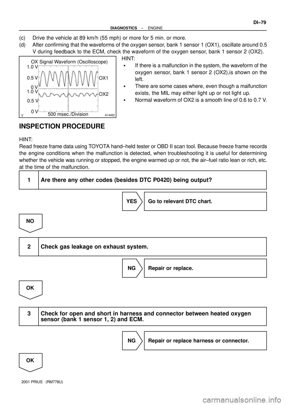
A14462
OX Signal Waveform (Oscilloscope)
500 msec./DivisionOX1
OX2 1.0 V
0.5 V
0 V
1.0 V
0.5 V
0 V
± DIAGNOSTICSENGINE
DI±79
2001 PRIUS (RM778U)
(c) Drive the vehicle at 89 km/h (55 mph) or more for 5 min. or more.
(d) After confirming that the waveforms of the oxygen sensor, bank 1 sensor 1 (OX1), oscillate around 0.5
V during feedback to the ECM, check the waveform of the oxygen sensor, bank 1 sensor 2 (OX2).
HINT:
�If there is a malfunction in the system, the waveform of the
oxygen sensor, bank 1 sensor 2 (OX2),is shown on the
left.
�There are some cases where, even though a malfunction
exists, the MIL may either light up or not light up.
�Normal waveform of OX2 is a smooth line of 0.6 to 0.7 V.
INSPECTION PROCEDURE
HINT:
Read freeze frame data using TOYOTA hand±held tester or OBD II scan tool. Because freeze frame records
the engine conditions when the malfunction is detected, when troubleshooting it is useful for determining
whether the vehicle was running or stopped, the engine warmed up or not, the air±fuel ratio lean or rich, etc.
at the time of the malfunction.
1 Are there any other codes (besides DTC P0420) being output?
YES Go to relevant DTC chart.
NO
2 Check gas leakage on exhaust system.
NG Repair or replace.
OK
3 Check for open and short in harness and connector between heated oxygen
sensor (bank 1 sensor 1, 2) and ECM.
NG Repair or replace harness or connector.
OK
Page 683 of 1943
DI±80
± DIAGNOSTICSENGINE
2001 PRIUS (RM778U)
4 Check oxygen sensor (bank 1 sensor 1) (See page DI±50).
NG Repair or replace.
OK
5 Check oxygen sensor (bank 1 sensor 2) (See page DI±59).
NG Repair or replace.
OK
Replace three±way catalytic converter.
Page 686 of 1943
± DIAGNOSTICSENGINE
DI±83
2001 PRIUS (RM778U)
�When the ENGINE RUN TIME in the freeze frame data is less than 200 seconds, carefully check the
VSV for EVAP, charcoal canister and vapor pressure sensor.
1 Check whether hose close to fuel tank have been modified, and check whether
there are signs of any accident near fuel tank or charcoal canister.
CHECK:
Check for cracks, deformation and loose connection of the following parts:
�Fuel tank
�Charcoal canister
�Fuel tank filler pipe
�Hoses and tubes around fuel tank and charcoal canister
NG Repair or replace.
OK
2 Check that fuel tank cap is TOYOTA genuine parts.
NG Replace to TOYOTA genuine parts.
OK
3 Check that fuel tank cap is correctly installed.
NG Correctly install fuel tank cap.
OK
4 Check fuel tank cap (See page EC±7).
NG Replace fuel tank cap.
OK