Page 964 of 1943
DI±386
± DIAGNOSTICSANTI±LOCK BRAKE SYSTEM WITH EBD & RBS
2001 PRIUS (RM778U)
INSPECTION PROCEDURE
1 Check brake fluid level.
CHECK:
Check the amount of fluid in the brake reservoir.
NG Check and repair brake fluid leakage and add
fluid.
OK
2 Check brake fluid level warning switch (See page BE±2).
NG Replace brake fluid level warning switch.
OK
3 Check for open circuit in all the harness and components connected to brake
fluid level warning light (See page IN±41).
NG Repair or replace harness or connector.
OK
Check and replace brake ECU.
Page 977 of 1943

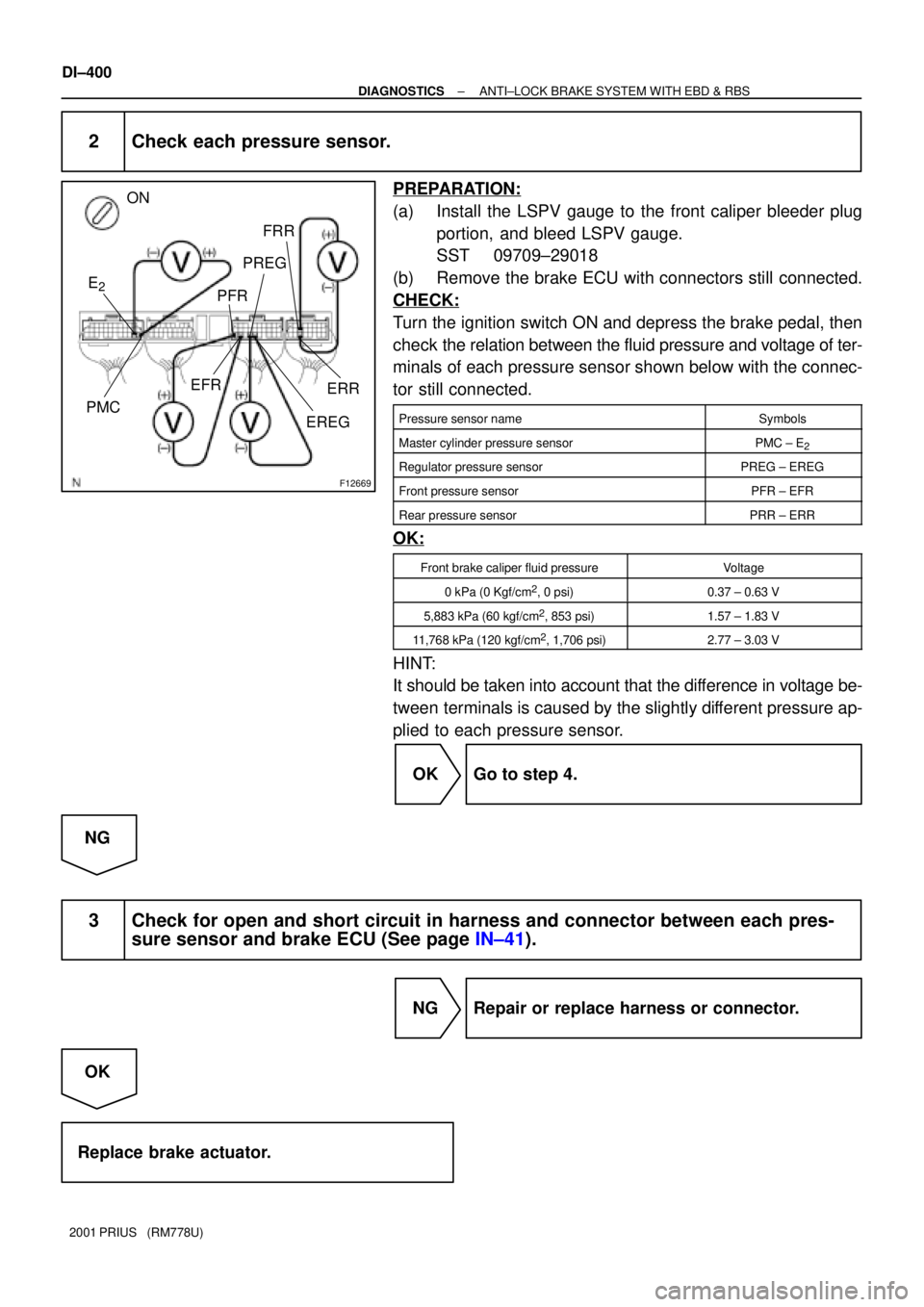
F12669
ON
E
2
FRR
PREG
PFR
PMC
EREGERR
EFR
DI±400
± DIAGNOSTICSANTI±LOCK BRAKE SYSTEM WITH EBD & RBS
2001 PRIUS (RM778U)
2 Check each pressure sensor.
PREPARATION:
(a) Install the LSPV gauge to the front caliper bleeder plug
portion, and bleed LSPV gauge.
SST 09709±29018
(b) Remove the brake ECU with connectors still connected.
CHECK:
Turn the ignition switch ON and depress the brake pedal, then
check the relation between the fluid pressure and voltage of ter-
minals of each pressure sensor shown below with the connec-
tor still connected.
Pressure sensor nameSymbols
Master cylinder pressure sensorPMC ± E2
Regulator pressure sensorPREG ± EREG
Front pressure sensorPFR ± EFR
Rear pressure sensorPRR ± ERR
OK:
Front brake caliper fluid pressureVoltage
0 kPa (0 Kgf/cm2, 0 psi)0.37 ± 0.63 V
5,883 kPa (60 kgf/cm2, 853 psi)1.57 ± 1.83 V
11,768 kPa (120 kgf/cm2, 1,706 psi)2.77 ± 3.03 V
HINT:
It should be taken into account that the difference in voltage be-
tween terminals is caused by the slightly different pressure ap-
plied to each pressure sensor.
OK Go to step 4.
NG
3 Check for open and short circuit in harness and connector between each pres-
sure sensor and brake ECU (See page IN±41).
NG Repair or replace harness or connector.
OK
Replace brake actuator.
Page 978 of 1943
± DIAGNOSTICSANTI±LOCK BRAKE SYSTEM WITH EBD & RBS
DI±401
2001 PRIUS (RM778U)
4 Check whether or not the brake ECU terminal STP input voltage is changed
when the stop light switch is turned on and off.
NO Check the stop light switch circuit (See page
BE±2).
YES
Check and replace brake ECU.
Page 985 of 1943
F12680
Battery B±G F13 1
FL Block
No. 2 F11
1
H15
High Mounted
Stop Light 2HR±B STOP
C Instrument Panel J/B
W
2 1Stop Light Switch
G±W
5IB1 2K
2G±W
A
AJ14
J/C
G±W 9Brake ECU
STP
G±WB11
2 1
W±B9 1 2E
BI 1
BKR7
Stop Light RH
W±B W±BW±BJ30
5E
R6
Stop Light LH
G±W
J30
J31J31C
G±W
G±W W±B
C C
C
J32 J33J33J/C J/C1
FL Block
No. 1E
DC/DC
MAIN DI±408
± DIAGNOSTICSANTI±LOCK BRAKE SYSTEM WITH EBD & RBS
2001 PRIUS (RM778U)
DTC C1249/49 Stop Light Switch Circuit
CIRCUIT DESCRIPTION
DTC No.DTC Detecting ConditionTrouble Area
C1249/49
When the ignition switch is ON, the condition that the termi-
nal STP in brake ECU is 3 ± 12 V continues for 1 sec. or
more.�Stop light switch
�Stop light switch circuit
WIRING DIAGRAM
DI1GO±09
Page 986 of 1943
F12407
LOCK
STP
± DIAGNOSTICSANTI±LOCK BRAKE SYSTEM WITH EBD & RBS
DI±409
2001 PRIUS (RM778U)
INSPECTION PROCEDURE
1 Check operation of the stop light switch.
CHECK:
Check that the stop light lights up when brake pedal is depressed and turns off when the brake pedal is re-
leased.
OK Go to step 3.
NG
2 Check stop light circuit (See page BE±2).
NG Repair or replace stop light circuit.
OK
3 Check voltage between terminal STP of brake ECU and body ground.
PREPARATION:
Remove the brake ECU with connectors still connected.
CHECK:
Measure voltage between terminal STP of brake ECU and body
ground when brake pedal is depressed.
OK:
Voltage: 8 ± 14 V
OK Check and replace brake ECU.
NG
Page 987 of 1943
DI±410
± DIAGNOSTICSANTI±LOCK BRAKE SYSTEM WITH EBD & RBS
2001 PRIUS (RM778U)
4 Check for open circuit in harness and connector between brake ECU and stop
light switch (See page IN±41).
NG Repair or replace harness or connector.
OK
Proceed to next circuit inspection on prob-
lem symptoms table (See page DI±365).
Page 1016 of 1943
DI±440
± DIAGNOSTICSANTI±LOCK BRAKE SYSTEM WITH EBD & RBS
2001 PRIUS (RM778U)
INSPECTION PROCEDURE
1 Check that brake ECU connectors are securely connected to brake ECU.
NO Connect connectors to brake ECU.
YES
2 Is DTC output?
Check DTC on page DI±353.
YES Repair circuit indicated by output code.
NO
3 Is normal code displayed?
YES Check ABS solenoid relay. Check for short cir-
cuit in harness and connector between ABS so-
lenoid relay and DLC3 (See page IN±41).
NO
4 Does ABS warning light go off?
YES Check for open or short circuit in harness and
connector between ECU±IG fuse and brake ECU
(See page IN±41).
NO
Page 1017 of 1943

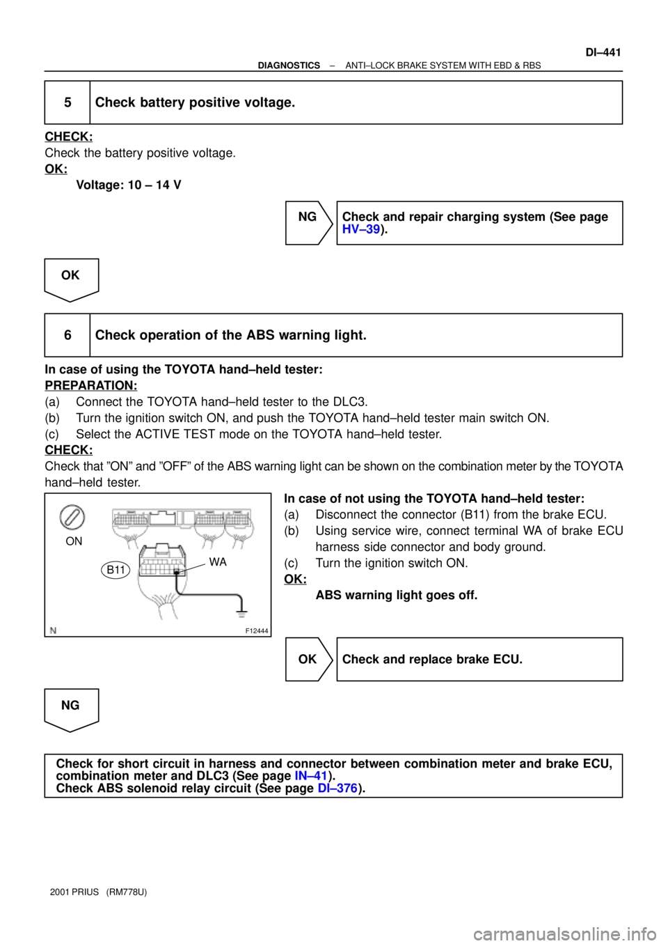
F12444
ON
WA
B11
± DIAGNOSTICSANTI±LOCK BRAKE SYSTEM WITH EBD & RBS
DI±441
2001 PRIUS (RM778U)
5 Check battery positive voltage.
CHECK:
Check the battery positive voltage.
OK:
Voltage: 10 ± 14 V
NG Check and repair charging system (See page
HV±39).
OK
6 Check operation of the ABS warning light.
In case of using the TOYOTA hand±held tester:
PREPARATION:
(a) Connect the TOYOTA hand±held tester to the DLC3.
(b) Turn the ignition switch ON, and push the TOYOTA hand±held tester main switch ON.
(c) Select the ACTIVE TEST mode on the TOYOTA hand±held tester.
CHECK:
Check that ºONº and ºOFFº of the ABS warning light can be shown on the combination meter by the TOYOTA
hand±held tester.
In case of not using the TOYOTA hand±held tester:
(a) Disconnect the connector (B11) from the brake ECU.
(b) Using service wire, connect terminal WA of brake ECU
harness side connector and body ground.
(c) Turn the ignition switch ON.
OK:
ABS warning light goes off.
OK Check and replace brake ECU.
NG
Check for short circuit in harness and connector between combination meter and brake ECU,
combination meter and DLC3 (See page IN±41).
Check ABS solenoid relay circuit (See page DI±376).