Page 435 of 2572

120
Headlight with Daytime Running Light
1. Daytime Running Light Operation
The headlight is turned on when all the following conditions are satisfied
*When the ignition swit")
2005 HIGHLANDER (EWD592U)
120
Headlight with Daytime Running Light
1. Daytime Running Light Operation
The headlight is turned on when all the following conditions are satisfied
*When the ignition switch is ON position
*When the generator is generating electricity
*When the light control SW is OFF position
*When the parking brake SW is OFF position
2. Headlight Operation
*The headlight comes on at the LOW position when the dimmer SW is turned to the low beam position with the light control
SW being HEAD position.
*If the dimmer SW is turned to the HIGH position with the light control SW being HEAD position, the headlight comes on at
the high beam position. Moreover, the high beam indicator light appears on the combination meter.
*Regardless of the light control SW positions, the headlight comes on at the low beam position when the dimmer SW is
turned to FLASH position. Moreover, the high beam indicator light appears on the combination meter.
B9 (A), B10 (B), B12 (D) Body ECU
(D) 7-Ground : Always continuity
(D)14-Ground : Continuity with parking brake pedal depressed
(B)17-Ground : Continuity with the light control SW at HEAD position
(A) 2-Ground : Always continuity
(A) 5-Ground : Approx. 12 volts with the ignition SW at ON position
: PARTS LOCATION
CodeSee PageCodeSee PageCodeSee Page
B9A42H138 (3MZ-FE)H440 (2AZ-FE)
B10B42H140 (2AZ-FE)J139 (3MZ-FE)
B11C42H238 (3MZ-FE)J141 (2AZ-FE)
B12D42H240 (2AZ-FE)J339 (3MZ-FE)
C11A42H338 (3MZ-FE)J341 (2AZ-FE)
C12B42H340 (2AZ-FE)M343
C1342H438 (3MZ-FE)P343
: RELAY BLOCKS
CodeSee PageRelay Blocks (Relay Block Location)
222Engine Room R/B (Engine Compartment Left)
323Engine Room R/B No.3 (Engine Compartment Rear Left)
System Outline
Service Hints
Page 495 of 2572
2005 HIGHLANDER (EWD592U)
180
VSC and Tire Pressure Warning System
5
2 5
55IA1 IO2
MR 15 14
MRF1 2
IC2 6IC215
519 31
+BS RR+ RR-
1 2 FSW+
7
4J 3
4M 9
Y
R+ 45
B13
A25
28PKB
O
RL
1
S27
P 3ABS CUT RelayFL MAIN
3. 0W
Battery
WB
B- R
G- W
R- W B
GR
P Y
BRB B- OLG
B- R
2IO2
G- R
12 IA1
V RA24
RL- RL+6 2016 IC2 7IC22
1
Y- G
G
1 43CSW
41INIT
L- R
B- Y W W- B
W- B
IB
W- BT 6
4
121
P22
IC4 17 IC42
3J 44J6
ABS MTR Relay W- L
BM 25
1 89
50A ABS2 30A ABS1
5
5 5 51 51
32 32B- O
B
B
3F 13 4L74J 7
4N 1 4D 4 93G
IC
W- B
IL1 17 IC46
IF3 13
W
W- B
SB
P W- B
W- B W- B
IC4 11
LG
EH
W- B
1 GN D2
W- BF 7
(
*1) (
*1) (
*1) (
*1)
W- B 4C 3
W- B
ABS Speed Sensor Rear LH
ABS Speed Sensor Rear RH Br ake Pedal Load
Sensing SWFusible Link Block
Parking Brake SWPr essure SW
Skid Control ECU with Actuator
TRAC Off SW
Page 625 of 2572
2005 HIGHLANDER (EWD592U)
266
Navigation System
7. 5A IG1
1K 10
3D 13A 8
IB
LG SB WGR B W- B
W- B
BR
L W- B
14 7 5 12298
GND CG GTX+ GTX-IG ACC BATT
B 12 B11
7. 5A
RAD NO. 2
10A
ECU- IG
1K 31K9
A 12 A11 A103G 73A 1
+B1 ACC I G
TX3+ TX3 -
A 16 A7
4H 12
4M 9
1
OR LG
OBR
W GR
TC PKB G 5
D 3
V
13
TC
7. 5A
CRT
2
V
IK2 16
V
2
VVV
11 4D64H2A
10A DOME
3I 13A 10 IL211
83F 93FA A
6IL1
J17
3I 7
W
3E 33A 13 10 3I
GR
1J 6 IK3 123
3F 133G 653G
LV
BR
Y
P
IF3 4IF33
D D
O B P 3
J1 6LG
V G
V
411 MPD1 MPD2
V
G HAZA 8
R O
8
W
HAZ
T 83E 4
3B 9
IL2 20 Fr om Power Source System (
See Page 62)
M 3(
A)
, M 4(
B)
, M 5(
C)
Data Link
Connector 3 Gateway ECU
Ju nctio n
ConnectorJunction
Connector
Multi- Display
Parking Brake SW
Turn Signal
Flasher 1G 2
IM1 10
R2
1
A/T Indicator SW P 1R R
IM1 20
R- B L
L
Page 679 of 2572

377
2005 HIGHLANDER from Nov. 04 Prod. (OM48570U)
Rear (four- wheel drive models)
When jacking up your vehicle with the
jack, position the jack correctly as
shown in the i")
'05 HIGHLANDER_U (L/O 0409)
377
2005 HIGHLANDER from Nov. '04 Prod. (OM48570U)
Rear (four- wheel drive models)
When jacking up your vehicle with the
jack, position the jack correctly as
shown in the illustrations.
CAUTION
When jacking, be sure to observe the
following to reduce the possibility of
personal injury:
�Follow jacking instructions.
�Do not put any part of your body
under the vehicle supported by the
jack. Personal injury may occur.
�Do not start or run the engine while
your vehicle is supported by the
jack.
�Stop the vehicle on a level firm
ground, firmly set the parking brake
and put the transmission in Pº.
Block the wheels on the opposite
side of the jack up point if neces-
sary.
�Make sure to set the jack properly
in the jack point. Raising the ve-
hicle with jack improperly posi-
tioned will damage the vehicle or
may allow the vehicle to fall off the
jack and cause personal injury.
�Never get under the vehicle when
the vehicle is supported by the jack
alone; use vehicle support stands.
�Do not raise the vehicle with some-
one in the vehicle.
�When raising the vehicle, do not
place any objects on top of or un-
derneath the jack.
NOTICE
Make sure to place the jack correctly,
or your vehicle may be damaged.
Here is a list of parts and tools you will
need to perform do- it- yourself mainte-
nance. Remember all Toyota parts are de-
signed in metric sizes, so your tools must
be metric.
CHECKING THE ENGINE OIL LEVEL
Parts (if level is low):
�Toyota Genuine Motor Oilº or equiva-
lent
See page 380 in Section 7- 2 for de-
tails about engine oil selection.
Tools:
�Rag or paper towel
�Funnel (only for adding oil)
CHECKING THE ENGINE COOLANT
LEVEL
Parts (if level is low):
�Toyota Super Long Life Coolantº or
similar high quality ethylene glycol
based non- silicate, non- amine, non- ni-
trite, and non- borate coolant with long-
life hybrid organic acid technology.
Toyota Super Long Life Coolantº is a
mixture of 50% coolant and 50% deion-
ized water (for the U.S.A.) or 55%
coolant and 45% deionized water (for
Canada).
Parts and tools
Page 745 of 2572
F50610
Skid Control ECU with Actuator Combination Meter
B4
Brake Warning SW
Passenger Side J/B
Instrument Panel J/B
I15
Ignition SW
F7
FL Block Brake
IGN
AM2BRL
PKB
AM2 IG2
FL MAIN
BatteryC11 IF3 IC4 S27
IL1
S27 C12
C12IF3
IC4
4E 4M
1C
1G4J
4MIC4
IC1Passenger Side J/B
P3
Parking
Brake SW J4
J/C
EB1
2
3 46
791011 13
1644
15
1
28 J6
J/C
11
9
16
6
1
10
1 1
1 B
PR V
W YSB
P
EER-B SB
R-W
LG
B
A L-Y GRW W-B
LG-B
05-854
- DIAGNOSTICSABS WITH EBD & BA & TRAC & VSC SYSTEM
1044 Author�: Date�:
BRAKE WARNING LIGHT CIRCUIT
CIRCUIT DESCRIPTION
The BRAKE warning light comes on when the brake fluid is insufficient, the parking brake is applied or the
EBD is defective.
WIRING DIAGRAM
05F1V-09
Page 746 of 2572

S27
BRL
- DIAGNOSTICSABS WITH EBD & BA & TRAC & VSC SYSTEM
05-855
1045 Author�: Date�:
INSPECTION PROCEDURE
HINT:
When releasing the parking brake, se")
G24767
Skid Control ECU
(harness side connector)
S27
BRL
- DIAGNOSTICSABS WITH EBD & BA & TRAC & VSC SYSTEM
05-855
1045 Author�: Date�:
INSPECTION PROCEDURE
HINT:
When releasing the parking brake, set the chocks to hold the vehicle for safety.
1 CHECK BRAKE FLUID
(a) Release the parking brake pedal.
(b) Check that the brake fluid level is proper.
NG ADD BRAKE FLUID
OK
2 CHECK DTC FOR ABS
(a) Are the DTC recorded? (see page 05-765)
NO Go to step 3
YES
REPAIR CIRCUIT INDICATED BY OUTPUT CODE
3 INSPECT BRAKE WARNING LIGHT
WHEN USING HAND-HELD TESTER:
(a) Connect the hand-held tester to the DLC3.
(b) Start the engine.
(c) Select the item ºBRAKE WARN LIGHTº in the ACTIVE TEST and operate the BRAKE warning light
on the hand-held tester.
ItemVehicle Condition / Test DetailsDiagnostic Note
BRAKE WRN LIGHTTurns BRAKE warning light ON / OFFObserve combination me-
ter
(d) Check that ºONº and ºOFFº of the BRAKE warning light are indicated on the combination meter when
using the hand-held tester.
OK:
Turn the BRAKE warning light on or off in accordance with the hand-held tester.
WHEN NOT USING HAND-HELD TESTER:
(a) Turn the ignition switch off and disconnect the connector
from the skid control ECU.
(b) Ground terminal BRL of the skid control ECU.
(c) Turn the ignition switch to the ON position.
(d) Check that the brake warning light.
OK:
Turn the light on or off in accordance with the connec-
tion of terminal BRL and body ground.
NG Go to step 4
OK
REPLACE ABS & TRACTION ACTUATOR ASSY (SEE PAGE 32-37)
Page 747 of 2572

Parking Brake Switch
(harness side connector)S27
PKB
P3
PKB
G26237
Brake Fluid Level Warning Switch")
G26238
Parking Brake Switch
P3Push Release
G26242G26243
Skid Control ECU
(harness side connector)
Parking Brake Switch
(harness side connector)S27
PKB
P3
PKB
G26237
Brake Fluid Level Warning Switch
B4
05-856
- DIAGNOSTICSABS WITH EBD & BA & TRAC & VSC SYSTEM
1046 Author�: Date�:
4 INSPECT PARKING BRAKE SWITCH ASSY
(a) Remove the parking brake switch connector.
(b) Measure the resistance according to the value(s) in the
table below.
Standard:
Tester ConnectionSwitch ConditionSpecified Condition
P3-1 - Ground partReleasedBelow 1 W
P3-1 - Ground partPushed in10 kW or higher
NG REPLACE PARKING BRAKE SWITCH ASSY
OK
5 CHECK HARNESS OR CONNECTOR(SKID CONTROL ECU - PARKING BRAKE
SWITCH)
(a) Disconnect the skid control ECU connector and the park-
ing brake switch connector.
(b) Measure the resistance according to the value(s) in the
table below.
Standard:
Tester ConnectionSpecified Condition
S27-28 (PKB) - P3-1 (PKB)Below 1 W
(c) Measure the resistance according to the value(s) in the
table below.
Standard:
Tester ConnectionSpecified Condition
S27-28 (PKB) - Body ground10 kW or higher
NG REPAIR OR REPLACE HARNESS OR
CONNECTOR
OK
6 INSPECT BRAKE FLUID LEVEL WARNING SWITCH
(a) Remove the reservoir tank cap and strainer.
(b) Disconnect the brake fluid level warning switch connec-
tor.
(c) Measure the resistance according to the value(s) in the
table below.
Standard:
Tester ConnectionSwitch ConditionSpecified Condition
(B4-1) - (B4-2)Float UP10 kW or higher
(B4-1) - (B4-2)Float DOWNBelow 1 W
NG REPLACE BRAKE FLUID LEVEL WARNING
SWITCH
OK
Page 1362 of 2572
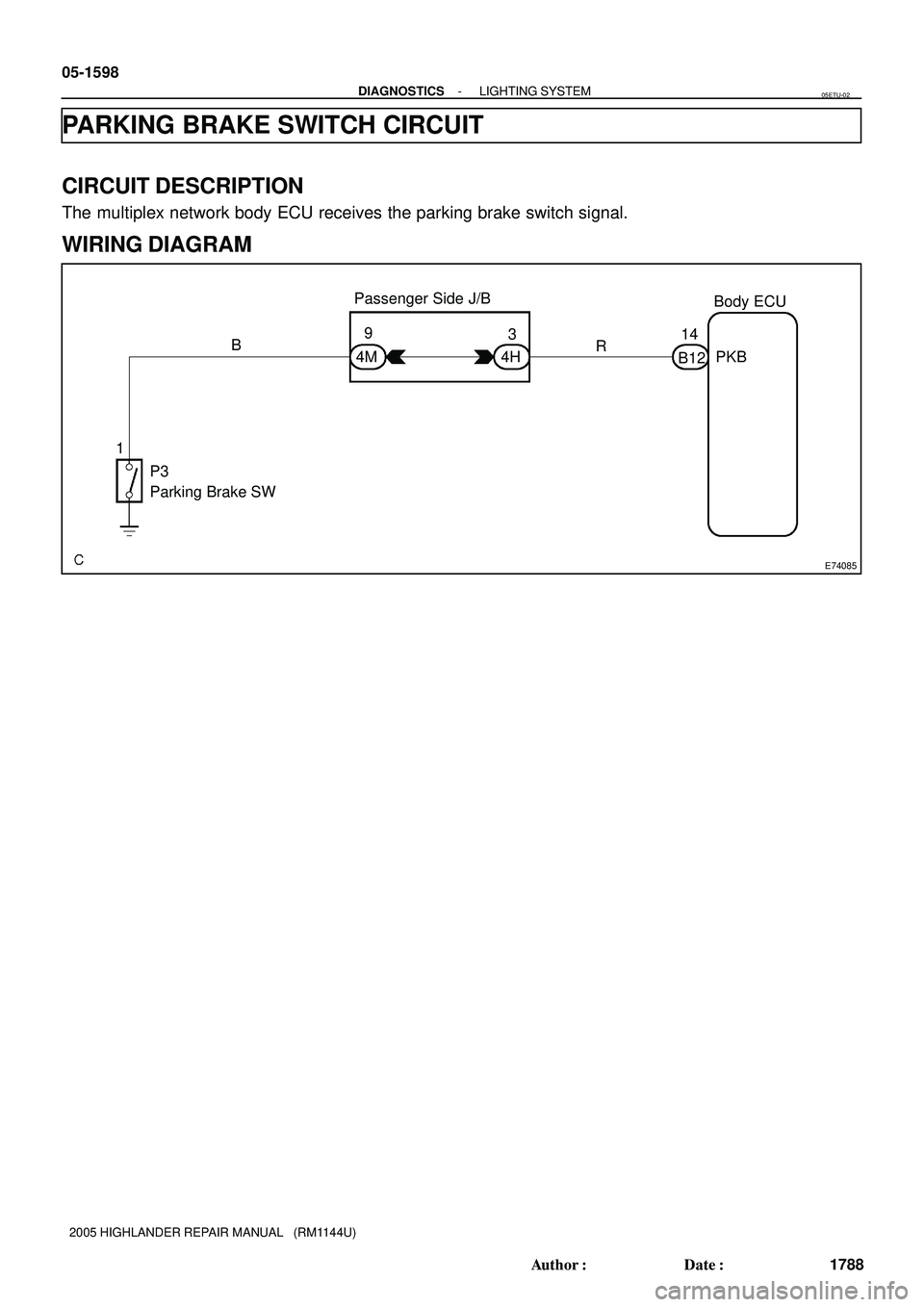
E74085
Passenger Side J/B
Body ECU
P3
Parking Brake SW9
4M B
13
4HR14
B12PKB 05-1598
- DIAGNOSTICSLIGHTING SYSTEM
1788 Author�: Date�:
2005 HIGHLANDER REPAIR MANUAL (RM1144U)
PARKING BRAKE SWITCH CIRCUIT
CIRCUIT DESCRIPTION
The multiplex network body ECU receives the parking brake switch signal.
WIRING DIAGRAM
05ETU-02

180
VSC and Tire Pressure Warning System
5
2 5
55IA1 IO2
MR 15 14
MRF1 2
IC2 6IC215
519 31
+BS RR+ RR-
1 2 FSW+
7
4J 3
4M 9
Y
R+ 45
B13
A25
28PKB
O
RL
1
S27
P 3ABS CUT RelayF")

266
Navigation System
7. 5A IG1
1K 10
3D 13A 8
IB
LG SB WGR B W- B
W- B
BR
L W- B
14 7 5 12298
GND CG GTX+ GTX-IG ACC BATT
B 12 B11
7. 5A
RAD NO. 2
10A
ECU- IG
1K 31K9
A 12 A")