Page 1377 of 1897
EM03Y-03
A10834
RH Fender Apron Seal
Generator Drive Belt
Engine Moving
Control Rod
No.2 RH Engine
Mounting Bracket
Ground Strap
Connector PS Pump Drive Belt
Engine Coolant Reservoir Hose
: Specified torque
64 (650, 47)
32 (320, 23)
N´m (kgf´cm, ft´lbf)
- ENGINE MECHANICALTIMING BELT
EM-13
997 Author�: Date�:
2001 AVALON (RM808U)
TIMING BELT
COMPONENTS
Page 1385 of 1897

Join
Line
Join
Line
Length = 460 mm
(18.11 in.)
A04693
SST
P18816
- ENGINE MECHANICALTIMING BELT
EM-25
1009 Author�: Date�:
2001 AVALON (RM808U)
14. INSTALL NO.1 TI")
P12982
Length = 240 mm (9.45 in.)
Join
Line
Join
Line
Length = 460 mm
(18.11 in.)
A04693
SST
P18816
- ENGINE MECHANICALTIMING BELT
EM-25
1009 Author�: Date�:
2001 AVALON (RM808U)
14. INSTALL NO.1 TIMING BELT COVER
(a) Check that the timing belt cover gaskets have cracks or
peeling, etc.
If the gasket has cracks or peeling, etc., replace it using these
steps:
�Using a screwdriver and gasket scraper, remove all
the old gasket material.
�Thoroughly clean all components to remove all the
loose material.
�Remove the backing paper from a new gasket and
install the gasket evenly to the part of the timing belt
cover shaded black in the illustration.
NOTICE:
When joining 2 gaskets, do not leave a gap between them.
Cut off any excess gasket.
�After installing the gasket, press down on it so that
the adhesive firmly sticks to the timing belt cover.
(b) Install the timing belt cover with the 4 bolts.
Torque: 8.5 N´m (85 kgf´cm, 74 in.´lbf)
15. INSTALL CRANKSHAFT PULLEY
(a) Align the pulley set key with the key groove of the pulley,
and slide on the pulley.
(b) Using SST, install the pulley bolt.
SST 09213-54015 (91651-60855), 09330-00021
Torque: 215 N´m (2,200 kgf´cm, 159 ft´lbf)
16. INSTALL NO.2 GENERATOR BRACKET
Install the generator bracket with the pivot bolt and nut. Do not
tighten the bolt yet.
Torque: (Nut): 28 N´m (290 kgf´cm, 21 ft´lbf)
17. INSTALL NO.2 RH ENGINE MOUNTING BRACKET
AND ENGINE MOVING CONTROL ROD
(See page EM-77)
18. CONNECT GROUND STRAP CONNECTORS
19. CONNECT ENGINE COOLANT RESERVOIR HOSE TO
WATER OUTLET
20. INSTALL PS PUMP DRIVE BELT
21. INSTALL GENERATOR DRIVE BELT
(See page CH-16)
22. INSTALL RH FENDER APRON SEAL
23. INSTALL RH FRONT WHEEL
24. VEHICLE ROAD TEST
Check for abnormal noise, shock, slippage, correct shift points
and smoothly operation.
Page 1386 of 1897
EM03Z-03
P18754
P18816
P18817
SST
P18819
SST
- ENGINE MECHANICALTIMING BELT
EM-15
999 Author�: Date�:
2001 AVALON (RM808U)
REMOVAL
1. REMOVE RH FRONT WHEEL
2. REMOVE RH FENDER APRON SEAL
3. REMOVE GENERATOR DRIVE BELT
(See page CH-6)
4. REMOVE PS PUMP DRIVE BELT
Loosen the 2 bolts, and remove the drive belt.
5. DISCONNECT ENGINE COOLANT RESERVOIR HOSE
FROM WATER OUTLET
6. DISCONNECT GROUND STRAP CONNECTORS
7. REMOVE ENGINE MOVING CONTROL ROD AND
NO.2 RH ENGINE MOUNTING BRACKET
(See page EM-72)
8. REMOVE NO.2 GENERATOR BRACKET
(a) Loosen the generator pivot bolt.
(b) Remove the nut and bracket.
9. REMOVE CRANKSHAFT PULLEY
(a) Using SST, remove the pulley bolt.
SST 09213-54015 (91651-60855), 09330-00021
(b) Using SST, remove the pulley.
SST 09950-50012 (09951-05010, 09952-05010,
09953-05010, 09953-05020, 09954-05020)
Page 1390 of 1897

VALVE CLEARANCE
INSPECTION
HINT:
Inspect and adjust")
EM03V-03
P18805
A05273
RH EX
RH IN
LH IN
LH EX 3 3
11Front
2266 EM-4
- ENGINE MECHANICALVALVE CLEARANCE
988 Author�: Date�:
2001 AVALON (RM808U)
VALVE CLEARANCE
INSPECTION
HINT:
Inspect and adjust the valve clearance when the engine is cold.
1. REMOVE RH FENDER APRON SEAL
2. DRAIN ENGINE COOLANT
3. REMOVE V-BANK COVER
(a) Using a 5 mm hexagon wrench, remove the 3 cap nuts.
(b) Loosen the V-bank cover fastener counterclockwise.
(c) Remove the V-bank cover.
4. REMOVE AIR INTAKE CHAMBER ASSEMBLY (See
page EM-31)
5. REMOVE IGNITION COILS
6. DISCONNECT UPPER RADIATOR HOSE FROM WA-
TER OUTLET
7. REMOVE CYLINDER HEAD COVERS
(See page EM-31)
8. SET NO.1 CYLINDER TO TDC/COMPRESSION
(a) Turn the crankshaft pulley, and align its groove with the
timing mark º0º of the No.1 timing belt cover.
(b) Check that the valve lifters on the No.1 (IN and EX) are
loose.
If not, turn the crankshaft 1 revolution (360°) and align the mark
as above.
9. INSPECT VALVE CLEARANCE
(a) Check only those valves indicated in the illustration.
(1) Using a feeler gauge, measure the clearance be-
tween the valve lifter and camshaft.
(2) Record out of specification valve clearance mea-
surements. They will be used later to determine the
required replacement adjusting shim.
Valve clearance (Cold):
Intake0.15 - 0.25 mm (0.006 - 0.010 in.)
Exhaust0.25 - 0.35 mm (0.010 - 0.014 in.)
Page 1393 of 1897
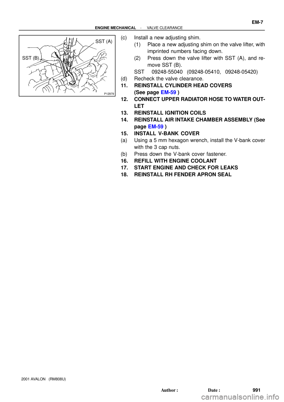
P12979
SST (A)
SST (B)
- ENGINE MECHANICALVALVE CLEARANCE
EM-7
991 Author�: Date�:
2001 AVALON (RM808U)
(c) Install a new adjusting shim.
(1) Place a new adjusting shim on the valve lifter, with
imprinted numbers facing down.
(2) Press down the valve lifter with SST (A), and re-
move SST (B).
SST 09248-55040 (09248-05410, 09248-05420)
(d) Recheck the valve clearance.
11. REINSTALL CYLINDER HEAD COVERS
(See page EM-59)
12. CONNECT UPPER RADIATOR HOSE TO WATER OUT-
LET
13. REINSTALL IGNITION COILS
14. REINSTALL AIR INTAKE CHAMBER ASSEMBLY (See
page EM-59)
15. INSTALL V-BANK COVER
(a) Using a 5 mm hexagon wrench, install the V-bank cover
with the 3 cap nuts.
(b) Press down the V-bank cover fastener.
16. REFILL WITH ENGINE COOLANT
17. START ENGINE AND CHECK FOR LEAKS
18. REINSTALL RH FENDER APRON SEAL
Page 1422 of 1897

� DTC No.
Indicates the diagnostic trouble code.
� Page or Instructions
Indicates the page where the inspection procedure
for each circuit is to be found, or gives instructions
for checking and repairs.
� Detection Item
Indicates the system of the problem or
contents of the problem.� Trouble Area
Indicates the suspect area of the
problem.
Mass Air Flow Circuit MalfunctionDetection Item
� Open or short in mass air flow meter circuit
� Mass air flow meter
� ECM DTC No.
(See page)Trouble AreaMIL* MemoryP0100
(DI-24)
P0101
(DI-28)
P0115
(DI-33)� Open or short in intake air temp. sensor
circuit
� Intake air temp. sensor
� ECM Intake Air Temp. Circuit
Malfunction P0110
(DI-29)
� Open or short in engine coolant temp. sensor circuit
� Engine coolant temp. sensor
� ECM
Throttle/ Pedal Position Sensor/Switch
ºAº Circuit MalfunctionEngine Coolant Temp.
Circuit Malfunction
� Open or short in throttle position sensor circuit
� Throttle position sensor
� ECM
DTC CHART (SAE Controlled)
HINT:
Parameters listed in the chart may not be exactly the same as your reading due to the type of instrument or other
factors.
If a malfunction code is displayed during the DTC check mode, check the circuit for that code listed in the table
below. For details of each code, turn to the page referred to under the ºSee pageº for the respective ºDTC No.º
in the DTC chart.
Mass Air Flow Circuit
Range/ Performance Problem� Mass air flow meter
� Throttle position sensor Throttle/ Pedal Position Sensor/ Switch
ºAº Circuit Range / Performance Prob-
lem P0116
(DI-37)Engine Coolant Temp.
Circuit Range/ Performance Problem� Engine coolant temp. sensor
� Cooling system
IN-26- INTRODUCTIONHOW TO TROUBLESHOOT ECU CONTROLLED
SYSTEMS
26 Author�: Date�:
2001 AVALON (RM808U)
4. DIAGNOSTIC TROUBLE CODE CHART
The inspection procedure is shown in the table below. This table permits efficient and accurate troubleshoot-
ing using the diagnostic trouble codes displayed in the diagnostic trouble code check. Proceed with trouble-
shooting in accordance with the inspection procedure given in the diagnostic chart corresponding to the
diagnostic trouble codes displayed. The engine diagnostic trouble code chart is shown below as an example.
Page 1442 of 1897
 H-FUSE
High Current Fuse
HIHigh
HIDHigh Intensity Discharge (Head Lamp)
HSGHousing
HTHard Top
HWSHeated Windshield System
IACIdle Ai")
- INTRODUCTIONTERMS
IN-37
37 Author�: Date�:
2001 AVALON (RM808U) H-FUSE
High Current Fuse
HIHigh
HIDHigh Intensity Discharge (Head Lamp)
HSGHousing
HTHard Top
HWSHeated Windshield System
IACIdle Air Control
ICIntegrated circuit
IDIIndirect Diesel Injection
IFSIndependent Front Suspension
IGIgnition
IIAIntegrated Ignition Assembly
INIntake (Manifold, Valve)
INTIntermittent
I/PInstrument Panel
IRSIndependent Rear Suspension
J/BJunction Block
J/CJunction Connector
KDKick-Down
LANLocal Area Network
LBLiftback
LCDLiquid Crystal Display
LEDLight Emitting Diode
LHLeft-Hand
LHDLeft-Hand Drive
L/H/WLength, Height, Width
LLCLong-Life Coolant
LNGLiquified Natural Gas
LOLow
LPGLiquified Petroleum Gas
LSDLimited Slip Differential
LSP & PVLoad Sensing Proportioning And Bypass Valve
LSPVLoad Sensing Proportioning Valve
MAX.Maximum
MICMicrophone
MILMalfunction Indicator Lamp
MIN.Minimum
MPMultipurpose
MPXMultiplex Communication System
M/TManual Transmission
MTMount
MTGMounting
NNeutral
NANatural Aspiration
No.Number
O/DOverdrive
Page 1445 of 1897

GLOSSARY OF SAE AND TOYOTA TERMS
This glossary lists all SAE-J1930 terms and abbreviations used in this manual in complianc")
IN0CI-02
IN-40
- INTRODUCTIONTERMS
40 Author�: Date�:
2001 AVALON (RM808U)
GLOSSARY OF SAE AND TOYOTA TERMS
This glossary lists all SAE-J1930 terms and abbreviations used in this manual in compliance with SAE rec-
ommendations, as well as their TOYOTA equivalents.
SAE
ABBREVIATIONSSAE TERMSTOYOTA TERMS
( )--ABBREVIATIONS
A/CAir ConditioningAir Conditioner
ACLAir CleanerAir Cleaner, A/CL
AIRSecondary Air InjectionAir Injection (AI)
APAccelerator Pedal-
B+Battery Positive Voltage+B, Battery Voltage
BAROBarometric PressureHAC
CACCharge Air CoolerIntercooler
CARBCarburetorCarburetor
CFIContinuous Fuel Injection-
CKPCrankshaft PositionCrank Angle
CLClosed LoopClosed Loop
CMPCamshaft PositionCam Angle
CPPClutch Pedal Position-
CTOXContinuous Trap Oxidizer-
CTPClosed Throttle PositionLL ON, Idle ON
DFIDirect Fuel Injection (Diesel)Direct Injection (DI)
DIDistributor Ignition-
DLC1
DLC2
DLC3Data Link Connector 1
Data Link Connector 2
Data Link Connector 31: Check Connector
2: Total Diagnosis Comunication Link (TDCL)
3: OBD II Diagnostic Connector
DTCDiagnostic Trouble CodeDiagnostic Code
DTMDiagnostic Test Mode-
ECLEngine Control Level-
ECMEngine Control ModuleEngine ECU (Electronic Control Unit)
ECTEngine Coolant TemperatureCoolant Temperature, Water Temperature (THW)
EEPROMElectrically Erasable Programmable Read Only Memory
Electrically Erasable Programmable Read Only Memory
(EEPROM),
Erasable Programmable Read Only Memory (EPROM)
EFEEarly Fuel EvaporationCold Mixture Heater (CMH), Heat Control Valve (HCV)
EGRExhaust Gas RecirculationExhaust Gas Recirculation (EGR)
EIElectronic IgnitionTOYOTA Distributorless Ignition (TDI)
EMEngine ModificationEngine Modification (EM)
EPROMErasable Programmable Read Only MemoryProgrammable Read Only Memory (PROM)
EVAPEvaporative EmissionEvaporative Emission Control (EVAP)
FCFan Control-
FEEPROMFlash Electrically Erasable Programmable
Read Only Memory-
FEPROMFlash Erasable Programmable Read Only Memory-
FFFlexible Fuel-
FPFuel PumpFuel Pump
GENGeneratorAlternator
GNDGroundGround (GND)