Page 433 of 1897
BO2OT-01
H04751
H12111
H12113
Clip
H12114
- BODYREAR DOOR
BO-17
1802 Author�: Date�:
2001 AVALON (RM808U)
DISASSEMBLY
1. REMOVE INSIDE HANDLE BEZEL
(a) Using a screwdriver, remove the cover.
HINT:
Tape the screwdriver tip before use.
(b) Remove the screw.
(c) Using a screwdriver, remove the inside handle bezel as
shown in the illustration.
HINT:
Tape the screwdriver tip before use.
2. REMOVE UPPER ARMREST BASE PANEL WITH
POWER WINDOW SWITCH
(a) Using a screwdriver, remove the upper armrest base pan-
el with power window switch.
HINT:
Tape the screwdriver tip before use.
(b) Disconnect the connector.
(c) Remove the power window switch from the upper armrest
base panel.
3. REMOVE REAR GUIDE BRACKET GARNISH
Using a screwdriver, remove the rear guide bracket garnish.
HINT:
Tape the screwdriver tip before use.
4. REMOVE DOOR TRIM
(a) Remove the 3 screws and 2 clips.
(b) Pull the trim upward to remove it.
Page 435 of 1897

10. REMOVE REAR DOOR OUTSIDE LOWER MOULDING
(a) Using a drill of less than ù3.2 mm (0.126 in.), drill out")
H12117
H02440
H02441
H02442
- BODYREAR DOOR
BO-19
1804 Author�: Date�:
2001 AVALON (RM808U)
10. REMOVE REAR DOOR OUTSIDE LOWER MOULDING
(a) Using a drill of less than ù3.2 mm (0.126 in.), drill out the
2 rivet heads.
HINT:
Gently and vertically put the drill to the rivet, and cut the rivet
flanges.
CAUTION:
Take care as the cut rivet is hot.
NOTICE:
Prizing the hole with a drill can lead to damage to the rivet
hole or breaking the drill.
(b) Using a clip remover, remove the clip.
(c) Remove the rear door outside lower moulding.
(d) Using a vacuum cleaner, remove the drilled rivets and
their dust from the inside of door panel.
HINT:
At the time of reassembly, please refer to the following item.
Using an air riveter with nose piece No. 1 or hand riveter with
nose piece No. 1, install the 3 rivets to the front door outside
lower moulding.
NOTICE:
�At the time of reassembly, please refer to the follow-
ing items.
�Do not prize a riveter, as riveter is damaged, it is not
tightened and the mandrel is bent.
�Do not tilt the riveter and disconnect the rivet from the
material while handling a riveter, as the materials are
not tightened firmly.
�Install the rivet while attaching materials, as they are
not tightened firmly.
11. REMOVE DOOR GLASS RUN
12. REMOVE REAR DOOR WINDOW GUIDE WITH GUIDE
PIECE PLATE
(a) Remove the bolt, nut, 3 screws and rear door window
guide with guide piece plate.
(b) Remove the guide piece plate from the rear door window
guide.
Page 436 of 1897

13. REMOVE REAR DOOR GLASS
(a) Open the door glass until the bolts appear in the service
hole.
(b) Remove the 2 bolts.
Torque:")
H12118
BO-20
- BODYREAR DOOR
1805 Author�: Date�:
2001 AVALON (RM808U)
13. REMOVE REAR DOOR GLASS
(a) Open the door glass until the bolts appear in the service
hole.
(b) Remove the 2 bolts.
Torque: 5.4 N´m (55 kgf´cm, 48 in.´lbf)
NOTICE:
Be careful not to drop the door glass.
(c) Pull the door glass upward to remove it.
14. REMOVE WINDOW REGULATOR ASSEMBLY
(a) Disconnect the connector, then remove the 4 nuts and
window regulator assembly.
Torque: 5.4 N´m (55 kgf´cm, 48 in.´lbf)
HINT:
Remove the window regulator assembly through the service
hole.
(b) Using a torx driver, remove the 3 torx screws and window
regulator motor from the window regulator guide assem-
bly.
HINT:
�At the time of reassembly, please refer to the following
items.
�Apply MP grease to the glass guide and rollers of window
regulator assembly.
�After installing the window regulator assembly, window
regulator assembly need to be re-initialized.
Refer to BE-80.
15. REMOVE DOOR LOCK
(a) Disconnect the control link from the outside handle.
(b) Disconnect the connector.
(c) Remove the 3 torx screws and door lock.
Torque:
Bolt: 5.4 N´m (55 kgf´cm, 48 in.´lbf)
Screw: 4.9 N´m (50 kgf´cm, 43 in.´lbf)
HINT:
Remove the door lock through the service hole.
HINT:
At the time of reassembly, please refer to the following item.
Apply adhesive to 3 screws.
Part No. 08833-00070, THREE BOND 1324 or equiva-
lent
(d) Remove the 2 screws and door lock protector from the
door lock.
Page 452 of 1897
 or moreSSTBattery
- BODYSEAT BELT PRETENSIONER
BO-133
1918 Author�: Date�:
2001 AVALON (RM808U)
(2) Connect the 2 SST, then connect them to the seat
belt")
H11079
SST SST
Battery
R13455
10 m (33 ft) or moreSSTBattery
- BODYSEAT BELT PRETENSIONER
BO-133
1918 Author�: Date�:
2001 AVALON (RM808U)
(2) Connect the 2 SST, then connect them to the seat
belt pretensioner.
SST 09082-00700, 09082-00740
NOTICE:
To avoid damaging the SST connector and wire harness,
do not lock the secondary lock of the twin lock.
(3) Move the SST to at least 10 m (33 ft) away from the
front of the vehicle.
(4) Close all the doors and windows of the vehicle.
NOTICE:
Take care not to damage the SST wire harness.
(5) Connect the SST red clip to the battery positive (+)
terminal and the black clip to the negative (-) termi-
nal.
(d) Activate the seat belt pretensioner.
(1) Confirm that no one is inside the vehicle or within 10
m (33 ft) area around the vehicle.
(2) Press the SST activation switch and activate the
seat belt pretensioner.
HINT:
The seat belt pretensioner operates simultaneously as the LED
of the SST activation switch lights up.
(e) Dispose of the front seat outer belt (with seat belt preten-
sioner).
CAUTION:
�The front seat outer belt is very hot when the seat belt
pretensioner is activated, so leave it alone for at least
30 minutes after activation.
�Use gloves and safety glasses when handling a front
seat outer belt with the activated seat belt pretension-
er.
�Always wash your hands with water after completing
the operation.
�Do not apply water, etc. to a front seat outer belt with
the activated seat belt pretensioner.
HINT:
When scrapping a vehicle, activate the seat belt pretensioner
and scrap the vehicle with the activated front seat outer belt still
installed.
2. ACTIVATION WHEN DISPOSING OF FRONT SEAT
OUTER BELT ONLY
NOTICE:
�When disposing of the front seat outer belt (with seat
belt pretensioner) only, never use the customer's ve-
hicle to activate the seat belt pretensioner.
Page 465 of 1897
BO2PO-01
H12167
Sliding Roof Glass
Drive Cable
Side Garnish
Rear Roof Drip Channel
Guide Block Guide CashingWindow Deflector Panel
Drive Gear
Map Light Bracket
Sliding Roof Panel StopperSliding Roof Housing
Sunshade Trim
Rear Frame
Sliding Roof Bracket
Sliding Roof Bracket
5.4 (55, 48 in.´lbf)
5.4 (55, 48 in.´lbf)
5.4 (55, 48 in.´lbf)
5.4 (55, 48 in.´lbf)
4.0 (41, 35 in.´lbf)
N´m (kgf´cm, ft´lbf)
: Specified torque Drain Hose
BO-78
- BODYSLIDING ROOF
1863 Author�: Date�:
2001 AVALON (RM808U)
COMPONENTS
Page 467 of 1897
H12171
H12172
H12173
H12174
BO-82
- BODYSLIDING ROOF
1867 Author�: Date�:
2001 AVALON (RM808U)
�Slide the cable forward or backward to align the 2 marks
as shown in the illustration.
�Slide the cable to the forefront with your hand.
(d) Employ the same manner described above to the other
side.
6. REMOVE WINDOW DEFLECTOR PANEL
7. REMOVE SLIDING ROOF HOUSING
(a) Remove the 2 screws from the sliding roof housing.
(b) Remove the 4 screws from the guide block.
(c) Employ the same manner described above to the other
side.
(d) Disconnect the sliding roof housing from the drive rail, and
slide the sliding roof housing forward.
(e) Remove the 2 guide blocks.
(f) Remove the sliding roof housing as shown in the illustra-
tion.
Page 824 of 1897
I13652
BatteryW-B
BM12
BB1
W-B
P151 22
5
Power WIndow
Motor RH
GP11
Power WIndow
Control Switch
Rear RH
D E
UB
DOWN
UP4
1
6L-W
R-BR-B R-B
G-B
G-BG-B 34
3 11 2 FL MAINB 1 1
F6 F10ALT W1G 1153
2
22
B5
B510RRD
RRU 12
1L PWR RELAY
P-B
6
IB2
P-B7
WLSWLG
D19
Driver
Door
ECU
1
1L RL P/W
10
1A BKJ11
J/C
A
W-B12
BA1
W-BP10
Power WIndow Control
Switch Rear LH
E
D
U R 212 P14
Power Window
Motor LHG
5DOWN
UP
B11
188
BA1
Y-R
Y-R
G-YG-Y
G-Y
PL-Y 4 6 3
3
2ID1
17
1B4
B422RLD
RLU
RBA1
ID1
BA1
IA1
RR P/W
FL Block
BB1
BB1
BB1IM2
IM2
IM2Body ECU
Driver Side J/BY-R
P
LG 3
- DIAGNOSTICSBODY CONTROL SYSTEM
DI-645
801 Author�: Date�:
2001 AVALON (RM808U)
Rear power window switch circuit
CIRCUIT DESCRIPTION
Power window switch circuit can be checked using DTC check. (Refer to DI-738)
WIRING DIAGRAM
DI6LS-01
Page 825 of 1897
DI-646
- DIAGNOSTICSBODY CONTROL SYSTEM
802 Author�: Date�:
2001 AVALON (RM808U)
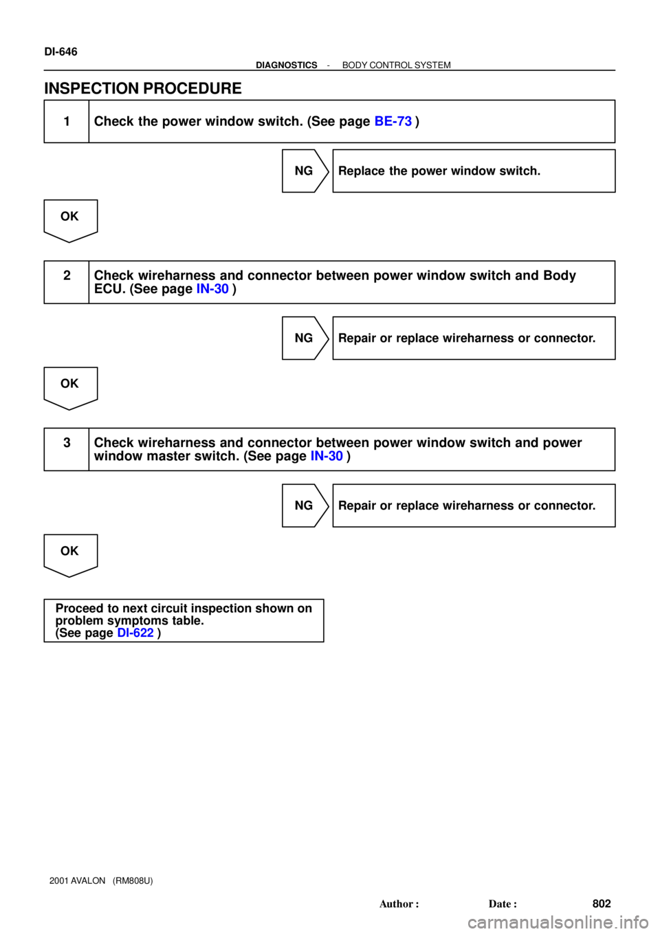
INSPECTION PROCEDURE
1 Check the power window switch. (See page BE-73)
NG Replace the power window switch.
OK
2 Check wireharness and connector between power window switch and Body
ECU. (See page IN-30)
NG Repair or replace wireharness or connector.
OK
3 Check wireharness and connector between power window switch and power
window master switch. (See page IN-30)
NG Repair or replace wireharness or connector.
OK
Proceed to next circuit inspection shown on
problem symptoms table.
(See page DI-622)