Page 674 of 1897
5
48
7 C11
Steering
Sensor
W-B R-B19 6
77
3B 3A 3A
3A(Shielded)
59
61
60
2 ABS & BA &
TRAC & VSC ECU
SS1
SS2")
F09819
Translate ECU
SS2 SS1 RSS VSC- VSC+ T5
T5
T5
T5
T54
5
18 17
6W
O
BR
L
B-W
(Shielded)5
48
7 C11
Steering
Sensor
W-B R-B19 6
77
3B 3A 3A
3A(Shielded)
59
61
60
2 ABS & BA &
TRAC & VSC ECU
SS1
SS2
FSS
R+ A20
BR
GR-R
W-B
A
AJ5
J/C
W-B
IG J/B No. 3A20
A20
A20 DI-292
- DIAGNOSTICSABS WITH EBD & BA & TRAC & VSC SYSTEM
448 Author�: Date�:
DTC C1208 / 54 Steering Angle Sensor Circuit
CIRCUIT DESCRIPTION
DTC No.DTC Detecting ConditionTrouble Area
C1208 / 54
Detection of any of conditions 1. through 7:
1. When the condition that ECU terminal IG1 voltage is 9.8
v or more, and does not receive data from steering angle
sensor continues for 0.1 sec. or more.
2. Sensor internal failure.
3. The offset value is out of range.
4. Sensor signal change higher.
5. Steering angle value difference between measured and
reference is out of range.
6. Steering sensor is not centered.
7. Steering sensor signal is out of range.
�Steering angle sensor
�Steering angle sensor circuit
WIRING DIAGRAM
DI6O4-01
Page 679 of 1897

F09821
ABS & BA &
TRAC & VSC ECU
1
A20
IG1
IJ Engine Room R/B No. 5J/B No. 3
J9
J/C
FL MAIN
BatteryEngine Room J/B
Y-R
J/B No. 4
18
4A 18
4H
Y-R Y-R11
3F 2
3C Driver Side J/B
Ignition Switch
ALTGND2 IG1 RelayECU-IG
No. 2
W-R13
1B
3
1B 1
1G
4
1C1
2
4 3
4
IG1
AM1AM1
B-L 2 W-L7
IF1W-L
55 21
B
1
2H 1
2G
F8 F101 1
F61GND1 29
A20
28
A20 W-B
W-B
W-B A
J5
J/C
J4
J/C A
AB
B W-B
W-B
W-B
IG W-B
W-B
FL Block W
B
- DIAGNOSTICSABS WITH EBD & BA & TRAC & VSC SYSTEM
DI-297
453 Author�: Date�:
2001 AVALON (RM808U)
DTC C1241 / 41 IG Power Source Circuit
CIRCUIT DESCRIPTION
This is the power source for the ECU, hence the brake actuators.
DTC No.DTC Detecting ConditionTrouble Area
C1241 / 41
At a vehicle speed of 6 km/h (4 mph) or more, the condition
that low battery voltage is 9.8 V or less (during non-opera-
tion of ABS control) or 9.4 V or less (during operation of
ABS control) and high battery voltage is more than 17.4 V,
continues for 0.5 sec. or more.
�Battery
�Charging system
�Power source circuit
WIRING DIAGRAM
DI6O6-03
Page 680 of 1897
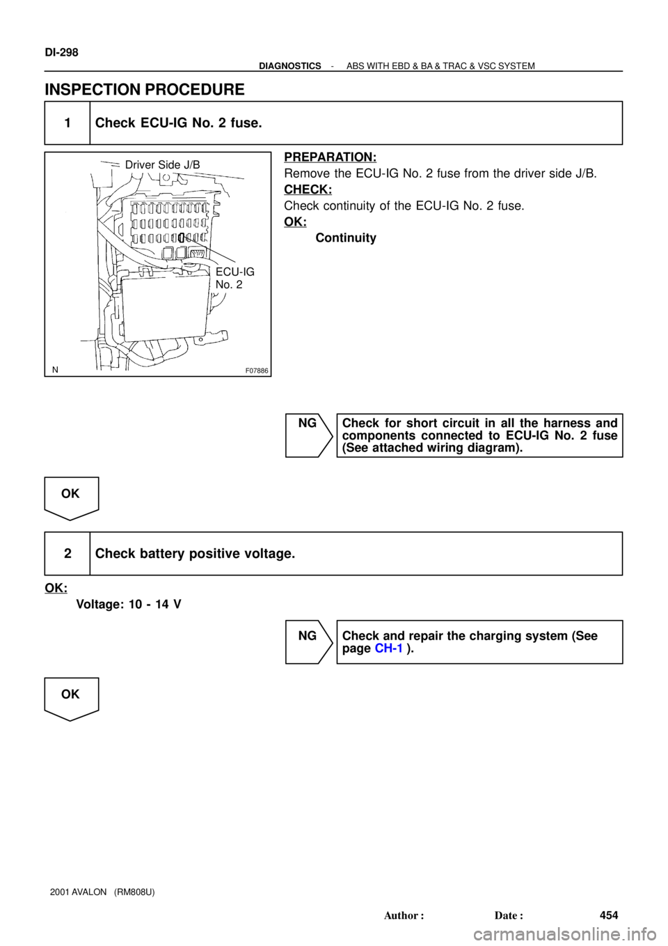
F07886
Driver Side J/B
ECU-IG
No. 2
DI-298
- DIAGNOSTICSABS WITH EBD & BA & TRAC & VSC SYSTEM
454 Author�: Date�:
2001 AVALON (RM808U)
INSPECTION PROCEDURE
1 Check ECU-IG No. 2 fuse.
PREPARATION:
Remove the ECU-IG No. 2 fuse from the driver side J/B.
CHECK:
Check continuity of the ECU-IG No. 2 fuse.
OK:
Continuity
NG Check for short circuit in all the harness and
components connected to ECU-IG No. 2 fuse
(See attached wiring diagram).
OK
2 Check battery positive voltage.
OK:
Voltage: 10 - 14 V
NG Check and repair the charging system (See
page CH-1).
OK
Page 682 of 1897
F09812
M2 Master Cylinder
Pressure SensorABS & BA &
TRAC & VSC ECU
VCM
E2 PMC
123
VCM
PMC
E2IF3
A20 A20A2065
66
67 IF3 IF3
29 8
P-L
R-L
BR-YP-L
R-L
BR-Y DI-300
- DIAGNOSTICSABS WITH EBD & BA & TRAC & VSC SYSTEM
456 Author�: Date�:
2001 AVALON (RM808U)
DTCC1246 / 53Master Cylinder Pressure Sensor Circuit
CIRCUIT DESCRIPTION
DTC No.DTC Detecting ConditionTrouble Area
C1246 / 53
When any of the following 1. through 3. is detected:
1. The voltage of sensor signal is out of range (less than
0.25 V, more than 4.75 V).
2. The sensor supply voltage is out of range (above 5.6 V,
below 4.4 V).
3. The sensor signal offset value is out of range.
�Master cylinder pressure sensor
�Master cylinder pressure sensor circuit
WIRING DIAGRAM
DI6O7-02
Page 685 of 1897
F09817
ABS & BA & TRAC
& VSC ECU
48
A20
STP
ALTJ/B No. 3
FL Block
FL MAIN
Battery Driver Side J/B
S4
Stop Light SwitchG-W
STOP
L5
Light Failure SensorR8
Rear Combination
Light RH
G-R
J12
J/C J/B No. 4
16
4D 16
4F 3
3F 3
3C 5
1B 3
1D
4 1E
5IK1
7 12R
Driver Side J/B
11
1D 1
1G W
1
F101
F6B2
G-R W-B BB
B3
6
C Stop R7
Rear Combination
Light LH
3
6 Stop
1 R-W
W-B H11
High Mounted
Stop Light
21
C
C
W-B
BM G-R W-B G-W G-W
G-W
G-W
G-W
J12
J/C
- DIAGNOSTICSABS WITH EBD & BA & TRAC & VSC SYSTEM
DI-303
459 Author�: Date�:
2001 AVALON (RM808U)
DTC C1249 / 58 Stop Light Switch Circuit
CIRCUIT DESCRIPTION
DTC No.DTC Detecting ConditionTrouble Area
C1249 / 58
After the ignition switch is turned ON, the condition that the
STP terminal voltage of ECU is 55 % to 75 % of supplied
voltage, continues for 1 sec. or more.�Stop light switch
�Stop light switch circuit
WIRING DIAGRAM
DI6O8-03
Page 688 of 1897
F09816
ABS & BA & TRAC
& VSC ECU
Engine RoomR/B No. 3
J/B No. 3
FL Block
FL MAIN7
A20
MR
2
A20 R+
27
A20
MT GR-L
ABS Motor Relay
W
B-L
Battery6
IE1
W-B
ABS GR-L
6
3AGR-R GR-R GR-R
3
3 3
31
23 4
Engine Room J/B 21
IF3
ALTABS No. 419
3H
ABS & BA & TRAC& VSC Actuator
6
A510
A5 L
L
OOEE
IF3
3 Engine Room R/B No. 5
12
215
5 5
5
B1
F61
F81
2G1
2H B DI-306
- DIAGNOSTICSABS WITH EBD & BA & TRAC & VSC SYSTEM
462 Author�: Date�:
2001 AVALON (RM808U)
DTCC1350 / 51Brake Actuator Pump Motor Failure
CIRCUIT DESCRIPTION
DTC No.DTC Detecting ConditionTrouble Area
C1350 / 51
When any of the following 1. through 3. is detected.
1. No motor voltage supply after actuator of the motor
relay.
2. A high level of motor voltage with no actuator of the mo-
tor relay.
3. The pump motor voltage is high level for a certain time
after the motor relay has elapsed.
�Brake actuator pump motor
�Brake actuator pump motor circuit
WIRING DIAGRAM
DI6OA-03
Page 690 of 1897
F09810
ABS & BA &
TRAC & VSC ECU
ML- ML+
A622
24
A20 A20
IE1 Precharge Pump
V
VW-R
W-R
IE18
9 A61
6
ML- ML+
ML- ML+ Brake Actuator
1 2 DI-308
- DIAGNOSTICSABS WITH EBD & BA & TRAC & VSC SYSTEM
464 Author�: Date�:
2001 AVALON (RM808U)
DTC C1351 / 52Precharge Pump Motor Circuit
CIRCUIT DESCRIPTION
DTC No.DTC Detecting ConditionTrouble Area
C1351 / 52
When any of the following 1. or 2. is detected:
1. After the ignition switch is turned ON, an open or short
circuit continues for 0.06 sec. or more.
2. The precharge pump motor voltage is out of range when
precharge pump if off.
�Precharge pump motor
�Precharge pump motor circuit
WIRING DIAGRAM
DI6OB-02
Page 693 of 1897
F09809
59
W
A20
SS1 ABS & BA & TRAC
& VSC ECU
61
A20
SS2
60
A20
FSS BR
(Shielded) Translate ECU
O 4
T5
17
T5 VSC+
VSC-
- DIAGNOSTICSABS WITH EBD & BA & TRAC & VSC SYSTEM
DI-31 1
467 Author�: Date�:
2001 AVALON (RM808U)
DTC 42 ECU Communication System Malfunction
CIRCUIT DESCRIPTION
The circuit is used to send TRAC & VSC control information from ABS & BA & TRAC & VSC ECU to the
translate ECU (VSC+, VSC-), engine control information and steering angle information from translate ECU
to ABS & BA & TRAC & VSC ECU
DTC No.DTC Detecting ConditionTrouble Area
42IG1 voltage is 9.5 V or more, and the condition that data
from ECU can not be received continues for 5 sec. or more.�VSC+ or VSC- circuit
�Translate ECU
�ABS & BA & TRAC & VSC ECU
WIRING DIAGRAM
DI6OC-03