Page 610 of 1897
F09803
ABS Actuator and ECU
+B
BAT
GND1
GND2 W-B
FL MAINFL Block
ALT
B-L
BatteryA717
A718
A719
A716 L
L
W-B
EE5 5
12 B
10 2F
42F 12H
12G
W-B
ED 1
F8 1
F6
BABS Engine Room R/B No. 5
Engine Room J/B
- DIAGNOSTICSANTI-LOCK BRAKE SYSTEM WITH ELECTRONIC
BRAKE FORCE DISTRIBUTION (EBD)DI-223
379 Author�: Date�:
2001 AVALON (RM808U)
DTC 21 - 24 ABS Solenoid Circuit
CIRCUIT DESCRIPTION
This solenoid goes on when signals are received from the ECU, and controls the pressure acting on the
wheel cylinders thus controlling the braking force.
DTC No.DTC Detecting ConditionTrouble Area
21, 22, 23, 24Solenoid signal does not match the check result.�Brake actuator
�Each solenoid circuit
WIRING DIAGRAM
DI6NE-01
Page 613 of 1897
F09802
ABS Actuator
and ECU
(Shielded)FL+
FL-
FR+
FR-
RL+
RL-
RR+ 2
B-WIE1A77
A76
A75
A74 BR
B-R
B-W
L
J1 J/C (Shielded)
(Shielded) 1 A8
ABS
Speed
Sensor
Front LH
L 2
1 A9
ABS
Speed
Sensor
Front RH1
IE12
IE13
BR
A BR
A
AA
A
BR BR BR
1
2 A29
ABS
Speed
Sensor
Rear LH
1
2 A30
ABS
Speed
Sensor
Rear RH
EEA79
A78
A72
A71
RR- LG
V
(Shielded) (Shielded) (Shielded)
(Shielded) (Shielded) (Shielded)LG
V LG
VBR
BR
IE18
IE17
IE16
IE19
IE110
IE111 ID111
ID122
ID121
IK110
IK112
IK111G
Y G
Y G
Y DI-226
- DIAGNOSTICSANTI-LOCK BRAKE SYSTEM WITH ELECTRONIC
BRAKE FORCE DISTRIBUTION (EBD)
382 Author�: Date�:
2001 AVALON (RM808U)
WIRING DIAGRAM
Page 618 of 1897
F09798
Battery W-B
W-BGND1ABS Actuator
and ECU
A715
EE EDY-R
IG1
W-R
ALT
AM1 Driver Side J/B
IG1 RelayECU-IG
No. 2
A719
GND2
A716 1H2
1C4 2
3 1
4 1G1
1B3
W42Ignition Switch
W-L
7IF1
W-L
5
52
1
BEngine Room R/B No. 5
FL Block Engine Room J/B
2H1
2G1
2F4
2F10 B-L
W-B F61
F81
F101
B
FL MAIN IGIG1 AM1
W-B
- DIAGNOSTICSANTI-LOCK BRAKE SYSTEM WITH ELECTRONIC
BRAKE FORCE DISTRIBUTION (EBD)DI-231
387 Author�: Date�:
2001 AVALON (RM808U)
DTC 41 Power Source Circuit
CIRCUIT DESCRIPTION
This is the power source for the ECU, hence the actuators.
DTC No.DTC Detecting ConditionTrouble Area
41
At a vehicle speed of about 6 km/h (4 mph), low battery
voltage is less than 9.4 V during non-operation of ABS
control or less than 8.8 V during operation of ABS control,
and high battery voltage is more than 17.4 V.�Battery
�Charging system
�Power source circuit
WIRING DIAGRAM
DI6NH-01
Page 619 of 1897
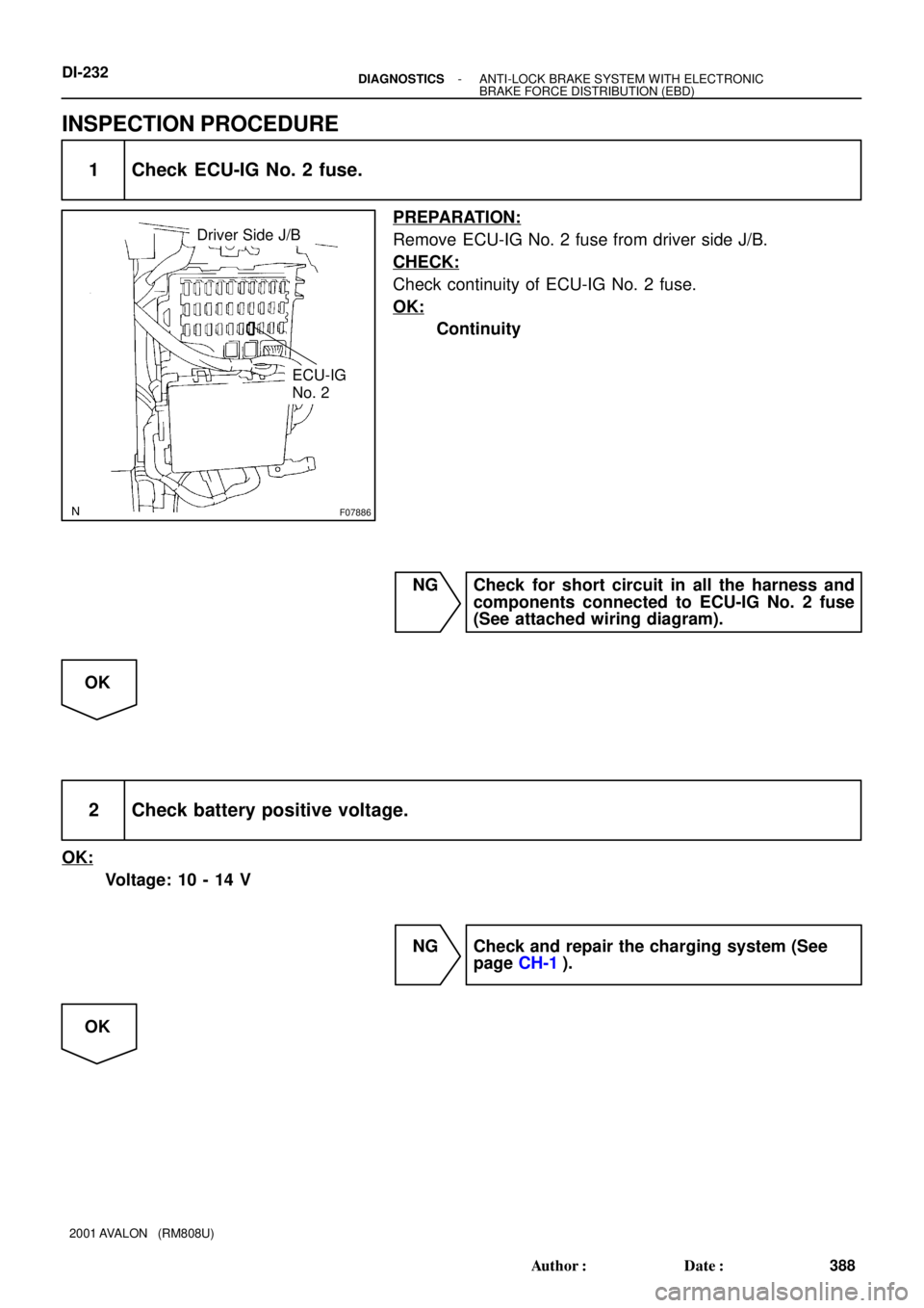
F07886
Driver Side J/B
ECU-IG
No. 2
DI-232- DIAGNOSTICSANTI-LOCK BRAKE SYSTEM WITH ELECTRONIC
BRAKE FORCE DISTRIBUTION (EBD)
388 Author�: Date�:
2001 AVALON (RM808U)
INSPECTION PROCEDURE
1 Check ECU-IG No. 2 fuse.
PREPARATION:
Remove ECU-IG No. 2 fuse from driver side J/B.
CHECK:
Check continuity of ECU-IG No. 2 fuse.
OK:
Continuity
NG Check for short circuit in all the harness and
components connected to ECU-IG No. 2 fuse
(See attached wiring diagram).
OK
2 Check battery positive voltage.
OK:
Voltage: 10 - 14 V
NG Check and repair the charging system (See
page CH-1).
OK
Page 621 of 1897
F09800
ABS Actuator
and ECU
A714
STP Driver Side J/B
BatteryJ/B No. 4
S4
Stop Light SwitchR7
Rear Combination
Light LH
G-W
14
IE1 G-W
G-W
J/B No. 3
16
4D 16
4F G-W3
3F 3
3C 5
1B 3
1D
4
1E
12R
11
1D STOP
FL Block
FL MAIN
L5
Light Failure
SensorStop
J12
J/C 1
1G W
1
F101
F6B5
IK1
7
Stop
36
G-R
B BBW-B
C
C
W-B
R8
Rear Combination
Light RH
36
G-R
G-R 2
1R-WH11
High Mounted
Stop Light
21
W-BC
C
W-B
BM ALTG-W G-W
G-W Driver Side J/B
J12
J/C DI-234
- DIAGNOSTICSANTI-LOCK BRAKE SYSTEM WITH ELECTRONIC
BRAKE FORCE DISTRIBUTION (EBD)
390 Author�: Date�:
2001 AVALON (RM808U)
DTC 58 Stop Light Switch Circuit
CIRCUIT DESCRIPTION
DTC No.DTC Detecting ConditionTrouble Area
58
Stop light switch circuit is open, and stop light switch volt-
age is in the level between 55 % and 75 % of the battery
voltage.�Stop light switch
�Stop light switch circuit
WIRING DIAGRAM
DI6NI-02
Page 625 of 1897
F09805
ABS Actuator and ECU
DLC2LG-R
LG-RLG-RTc 12
A7 7
1H 3B 4
Tc 4
EB5
1I 4
133A 3G
22 II2
W-BLG-R
DLC1 LG-R
LG-R6
4H 6
4A
Tc
E13J/B No. 4
Driver Side J/B J/B No. 3
11
F10163
DLC2
Tc E1
DLC1
Tc ON
- DIAGNOSTICSANTI-LOCK BRAKE SYSTEM WITH ELECTRONIC
BRAKE FORCE DISTRIBUTION (EBD)DI-245
401 Author�: Date�:
2001 AVALON (RM808U)
Tc Terminal Circuit
CIRCUIT DESCRIPTION
Connecting between terminals Tc and E1 of the DLC1 causes the ECU to display the DTC by flashing the
ABS warning light.
WIRING DIAGRAM
INSPECTION PROCEDURE
1 Check voltage between terminals Tc and E1.
CHECK:
(a) Turn the ignition switch ON.
(b) Measure the voltage between terminals Tc and E
1 of
DLC1 or terminal Tc of DLC2 and body ground.
OK:
Voltage: 10 - 14 V
OK If ABS warning light does not blink even after Tc
and E
1 are connected, the ECU may be defec-
tive.
NG
DI6NN-01
Page 627 of 1897
F09804
ABS Actuator and ECU
LG-B LG-B
Ts 11
A7 13
IE1 3
4BLG-B LG-B DLC1
Ts
W-BJ/B No. 4
E112
4A 11
II2
16
3
EB
- DIAGNOSTICSANTI-LOCK BRAKE SYSTEM WITH ELECTRONIC
BRAKE FORCE DISTRIBUTION (EBD)DI-247
403 Author�: Date�:
2001 AVALON (RM808U)
Ts Terminal Circuit
CIRCUIT DESCRIPTION
The sensor check circuit detects abnormalily in the speed sensor signal which cannot be detected by the
DTC check.
Connecting terminals Ts and E
1 of the DLC1 starts the check.
WIRING DIAGRAM
DI6NO-01
Page 638 of 1897
F09823
ABS & BA &
TRAC & VSC ECU
WA A2081
47 1
B
W-B
B
BJ4
J/C
W-B W-B
IG Battery FL MAINA21
Active
Light
Relay
F10F8 F61 1
1ALT
W W
W-B
B-L
2G
2H 11
5512 AM1
B
W-LIF17 W-L 22
Y-R
IG1 AM1 4
Ignition Switch W-R 1B 1C1G1B1D
4
3 4 3 1
1
213 10 GAUGE No. 1
ECU-IG
No. 2
Y-R3C
3D 2
11 R-B
R-B 4D
4FM6M6
4
Multi
Display 13 45 R-LR-L
4A4B
4H15
15 15
R-L 14
E1
ABS D2
DLC2
ABS
J/B No. 4
J/B No. 3 Driver Side J/B
Engine Room J/B
Engine Room R/B No. 5J/B No. 4
FL Block IG1
Relay
B
- DIAGNOSTICSABS WITH EBD & BA & TRAC & VSC SYSTEM
DI-325
481 Author�: Date�:
2001 AVALON (RM808U)
ABS Warning Light Circuit
WIRING DIAGRAM
DI6OI-03

FL+
FL-
FR+
FR-
RL+
RL-
RR+ 2
B-WIE1A77
A76
A75
A74 BR
B-R
B-W
L
J1 J/C (Shielded)
(Shielded) 1 A8
ABS
Speed
Sensor
Front LH
L 2
1 A9
ABS
Speed
Sensor
Front RH1")


DI-24")
