2001 SUZUKI GRAND VITARA Power
[x] Cancel search: PowerPage 537 of 656

8E-16 CRUISE CONTROL SYSTEM
Overdrive and TCC off Command Signal Circuit Check
Fig. for Step 1
Cruise Control Module Power and Ground Circuits Check
Fig. for Step 1Step Action Yes No
1 Overdrive off Command Signal Circuit Check
1) Disconnect connector from cruise control module with
ignition switch OFF.
2) Check for proper connection to cruise control module at
terminal E132-3.
3) If OK, turn ignition switch ON.
4) Check voltage between terminal E132-3 and ground.
Is it 10 –14 V?This signal circuit is
OK.Check “PNK/
BLU” wire for
open and short.
If OK, substitute
a known-good
PCM and
recheck.
Step Action Yes No
1 Power and Ground Circuits Check
1) Disconnect connector from cruise control module with
ignition switch OFF.
2) Check for proper connection to cruise control module at
terminals E132-12 and E132-11.
3) If OK, turn ignition switch ON.
4) Check voltage between terminals E132-12 and E132-11.
Does voltmeter indicate 10 – 14 V?Power and ground
circuits are OK.“BLU/BLK” or
“BLK” circuit is
open.
Page 578 of 656

AIR BAG SYSTEM 10B-1
10B
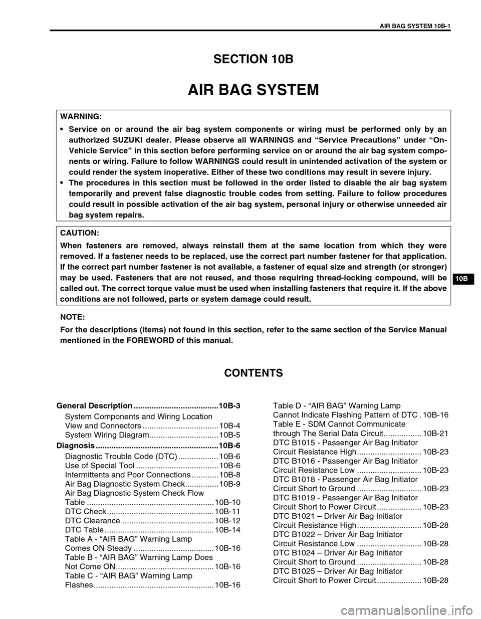
SECTION 10B
AIR BAG SYSTEM
CONTENTS
General Description ......................................10B-3
System Components and Wiring Location
View and Connectors .................................. 10B-4
System Wiring Diagram............................... 10B-5
Diagnosis .......................................................10B-6
Diagnostic Trouble Code (DTC) .................. 10B-6
Use of Special Tool ..................................... 10B-6
Intermittents and Poor Connections ............ 10B-8
Air Bag Diagnostic System Check............... 10B-9
Air Bag Diagnostic System Check Flow
Table ......................................................... 10B-10
DTC Check ................................................ 10B-11
DTC Clearance ......................................... 10B-12
DTC Table ................................................. 10B-14
Table A - “AIR BAG” Warning Lamp
Comes ON Steady .................................... 10B-16
Table B - “AIR BAG” Warning Lamp Does
Not Come ON ............................................ 10B-16
Table C - “AIR BAG” Warning Lamp
Flashes ...................................................... 10B-16Table D - “AIR BAG” Warning Lamp
Cannot Indicate Flashing Pattern of DTC . 10B-16
Table E - SDM Cannot Communicate
through The Serial Data Circuit................. 10B-21
DTC B1015 - Passenger Air Bag Initiator
Circuit Resistance High............................. 10B-23
DTC B1016 - Passenger Air Bag Initiator
Circuit Resistance Low ............................. 10B-23
DTC B1018 - Passenger Air Bag Initiator
Circuit Short to Ground ............................. 10B-23
DTC B1019 - Passenger Air Bag Initiator
Circuit Short to Power Circuit .................... 10B-23
DTC B1021 – Driver Air Bag Initiator
Circuit Resistance High............................. 10B-28
DTC B1022 – Driver Air Bag Initiator
Circuit Resistance Low ............................. 10B-28
DTC B1024 – Driver Air Bag Initiator
Circuit Short to Ground ............................. 10B-28
DTC B1025 – Driver Air Bag Initiator
Circuit Short to Power Circuit .................... 10B-28 WARNING:
Service on or around the air bag system components or wiring must be performed only by an
authorized SUZUKI dealer. Please observe all WARNINGS and “Service Precautions” under “On-
Vehicle Service” in this section before performing service on or around the air bag system compo-
nents or wiring. Failure to follow WARNINGS could result in unintended activation of the system or
could render the system inoperative. Either of these two conditions may result in severe injury.
The procedures in this section must be followed in the order listed to disable the air bag system
temporarily and prevent false diagnostic trouble codes from setting. Failure to follow procedures
could result in possible activation of the air bag system, personal injury or otherwise unneeded air
bag system repairs.
CAUTION:
When fasteners are removed, always reinstall them at the same location from which they were
removed. If a fastener needs to be replaced, use the correct part number fastener for that application.
If the correct part number fastener is not available, a fastener of equal size and strength (or stronger)
may be used. Fasteners that are not reused, and those requiring thread-locking compound, will be
called out. The correct torque value must be used when installing fasteners that require it. If the above
conditions are not followed, parts or system damage could result.
NOTE:
For the descriptions (items) not found in this section, refer to the same section of the Service Manual
mentioned in the FOREWORD of this manual.
Page 579 of 656

10B-2 AIR BAG SYSTEM
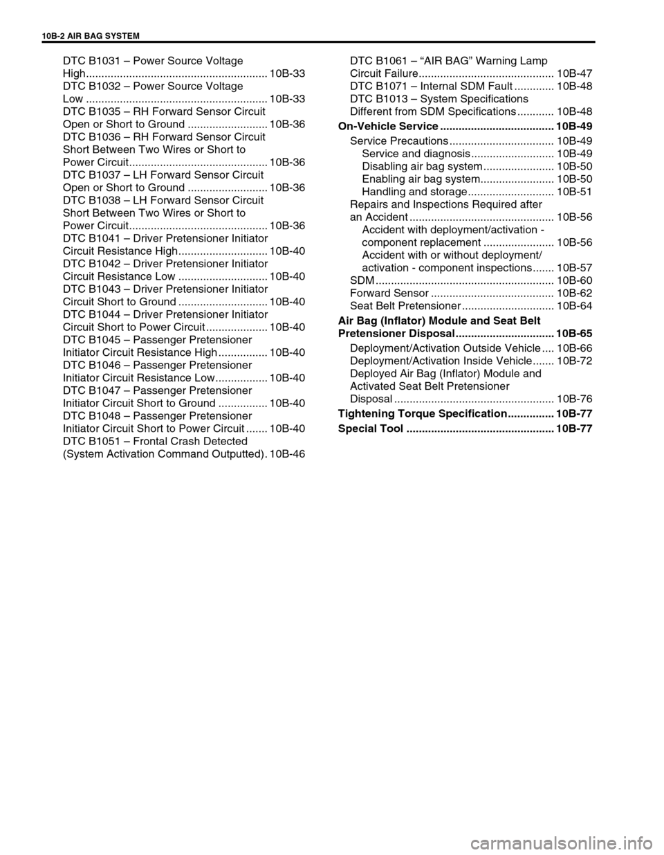
DTC B1031 – Power Source Voltage
High........................................................... 10B-33
DTC B1032 – Power Source Voltage
Low ........................................................... 10B-33
DTC B1035 – RH Forward Sensor Circuit
Open or Short to Ground .......................... 10B-36
DTC B1036 – RH Forward Sensor Circuit
Short Between Two Wires or Short to
Power Circuit............................................. 10B-36
DTC B1037 – LH Forward Sensor Circuit
Open or Short to Ground .......................... 10B-36
DTC B1038 – LH Forward Sensor Circuit
Short Between Two Wires or Short to
Power Circuit............................................. 10B-36
DTC B1041 – Driver Pretensioner Initiator
Circuit Resistance High............................. 10B-40
DTC B1042 – Driver Pretensioner Initiator
Circuit Resistance Low ............................. 10B-40
DTC B1043 – Driver Pretensioner Initiator
Circuit Short to Ground ............................. 10B-40
DTC B1044 – Driver Pretensioner Initiator
Circuit Short to Power Circuit .................... 10B-40
DTC B1045 – Passenger Pretensioner
Initiator Circuit Resistance High ................ 10B-40
DTC B1046 – Passenger Pretensioner
Initiator Circuit Resistance Low................. 10B-40
DTC B1047 – Passenger Pretensioner
Initiator Circuit Short to Ground ................ 10B-40
DTC B1048 – Passenger Pretensioner
Initiator Circuit Short to Power Circuit ....... 10B-40
DTC B1051 – Frontal Crash Detected
(System Activation Command Outputted). 10B-46DTC B1061 – “AIR BAG” Warning Lamp
Circuit Failure............................................ 10B-47
DTC B1071 – Internal SDM Fault ............. 10B-48
DTC B1013 – System Specifications
Different from SDM Specifications ............ 10B-48
On-Vehicle Service ..................................... 10B-49
Service Precautions .................................. 10B-49
Service and diagnosis ........................... 10B-49
Disabling air bag system ....................... 10B-50
Enabling air bag system........................ 10B-50
Handling and storage ............................ 10B-51
Repairs and Inspections Required after
an Accident ............................................... 10B-56
Accident with deployment/activation -
component replacement ....................... 10B-56
Accident with or without deployment/
activation - component inspections....... 10B-57
SDM .......................................................... 10B-60
Forward Sensor ........................................ 10B-62
Seat Belt Pretensioner .............................. 10B-64
Air Bag (Inflator) Module and Seat Belt
Pretensioner Disposal................................ 10B-65
Deployment/Activation Outside Vehicle .... 10B-66
Deployment/Activation Inside Vehicle....... 10B-72
Deployed Air Bag (Inflator) Module and
Activated Seat Belt Pretensioner
Disposal .................................................... 10B-76
Tightening Torque Specification............... 10B-77
Special Tool ................................................ 10B-77
Page 582 of 656

AIR BAG SYSTEM 10B-5
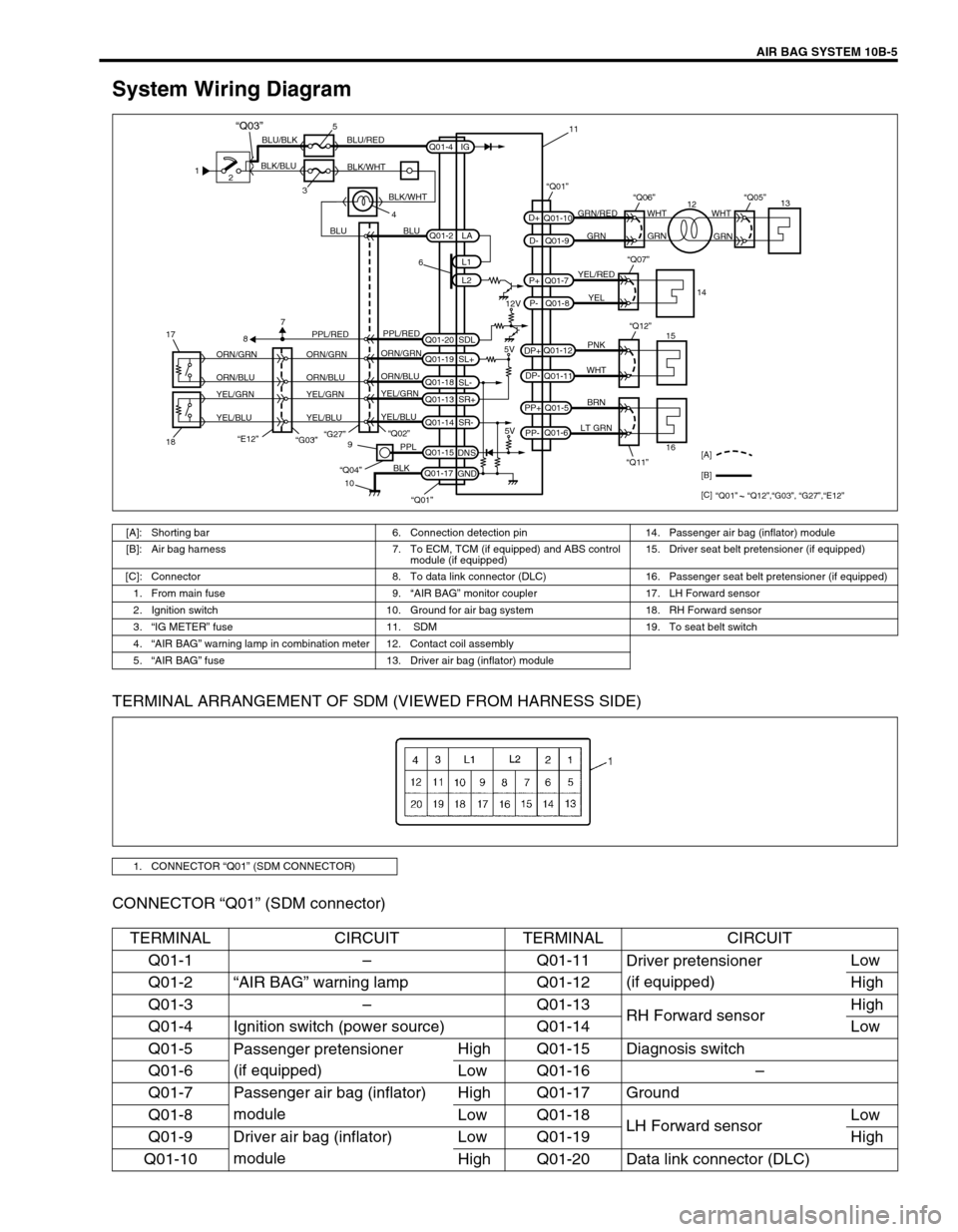
System Wiring Diagram
TERMINAL ARRANGEMENT OF SDM (VIEWED FROM HARNESS SIDE)
CONNECTOR “Q01” (SDM connector)
1
2
35
4 BLK/BLUBLU/BLK BLU/RED
BLK/WHT
BLU BLUGRN/RED
GRN GRNWHT WHT
GRN
YEL/RED
YEL
PNK
WHT
BRN
LT GRN
6
12V
5V 5V PPL/RED
ORN/GRN
ORN/BLU
YEL/GRN
YEL/BLUORN/GRN
ORN/BLU
YEL/GRN
YEL/BLUORN/GRN
ORN/BLU
YEL/GRN
YEL/BLUPPL/RED
87
“G27”
“E12”18 17“Q02”
“Q11” “Q12”9
10PPL
BLK
“Q04”
Q01-2
Q01-4
Q01-20Q01-7
Q01-8 Q01-10
Q01-9
Q01-12
Q01-11
Q01-5
Q01-6
Q01-15
Q01-17L1
L2 IG
SDL
Q01-19
SL+
Q01-18
SL-
Q01-13
SR+
Q01-14
SR-
DNS
GNDLA
PP- PP+DP- DP+P- P+D- D+
“Q07”
“Q06”“Q01”“Q05”
15
161413
12 11
[A]
[B]
[C]
“Q01” “Q12”,“G03”, “G27”,“E12”
“Q01”
BLK/WHT
“Q03”
“G03”
[A]: Shorting bar 6. Connection detection pin 14. Passenger air bag (inflator) module
[B]: Air bag harness 7. To ECM, TCM (if equipped) and ABS control
module (if equipped) 15. Driver seat belt pretensioner (if equipped)
[C]: Connector 8. To data link connector (DLC) 16. Passenger seat belt pretensioner (if equipped)
1. From main fuse 9.“AIR BAG” monitor coupler 17. LH Forward sensor
2. Ignition switch 10. Ground for air bag system 18. RH Forward sensor
3.“IG METER” fuse 11. SDM 19. To seat belt switch
4.“AIR BAG” warning lamp in combination meter 12. Contact coil assembly
5.“AIR BAG” fuse 13. Driver air bag (inflator) module
1. CONNECTOR “Q01” (SDM CONNECTOR)
TERMINAL CIRCUIT TERMINAL CIRCUIT
Q01-1–Q01-11
Driver pretensioner
(if equipped)Low
Q01-2“AIR BAG” warning lamp Q01-12 High
Q01-3–Q01-13
RH Forward sensorHigh
Q01-4 Ignition switch (power source) Q01-14 Low
Q01-5
Passenger pretensioner
(if equipped)High Q01-15 Diagnosis switch
Q01-6 Low Q01-16–
Q01-7 Passenger air bag (inflator)
moduleHigh Q01-17 Ground
Q01-8 Low Q01-18
LH Forward sensorLow
Q01-9 Driver air bag (inflator)
moduleLow Q01-19 High
Q01-10 High Q01-20 Data link connector (DLC)
Page 583 of 656

10B-6 AIR BAG SYSTEM
Diagnosis
Diagnostic Trouble Code (DTC)
The AIR BAG DIAGNOSTIC SYSTEM CHECK must always be the starting point of any air bag system diagno-
sis. The AIR BAG DIAGNOSTIC SYSTEM CHECK checks for proper “AIR BAG” warning lamp operation and
checks for air bag diagnostic trouble codes (DTCs) using on-board diagnosis function or SUZUKI scan tool.
Use of Special Tool
You should be familiar with the tools listed in this section under the heading SPECIAL TOOLS. You should be
able to measure voltage and resistance. You should be familiar with proper use of a scan tool such as Air Bag
Driver/Passenger Load Tool, Connector Test Adapter Kit and the Digital Multimeter.
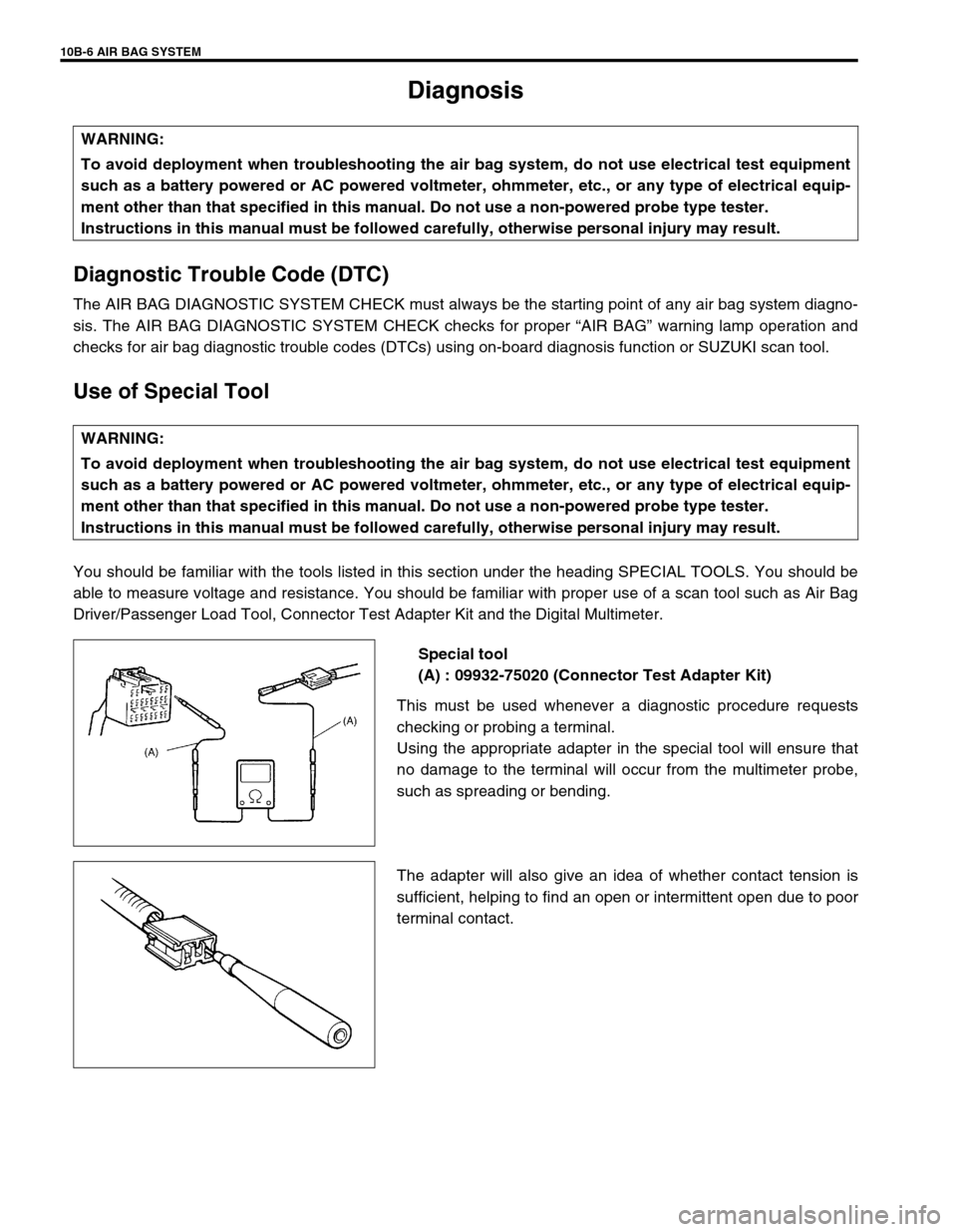
Special tool
(A) : 09932-75020 (Connector Test Adapter Kit)
This must be used whenever a diagnostic procedure requests
checking or probing a terminal.
Using the appropriate adapter in the special tool will ensure that
no damage to the terminal will occur from the multimeter probe,
such as spreading or bending.
The adapter will also give an idea of whether contact tension is
sufficient, helping to find an open or intermittent open due to poor
terminal contact. WARNING:
To avoid deployment when troubleshooting the air bag system, do not use electrical test equipment
such as a battery powered or AC powered voltmeter, ohmmeter, etc., or any type of electrical equip-
ment other than that specified in this manual. Do not use a non-powered probe type tester.
Instructions in this manual must be followed carefully, otherwise personal injury may result.
WARNING:
To avoid deployment when troubleshooting the air bag system, do not use electrical test equipment
such as a battery powered or AC powered voltmeter, ohmmeter, etc., or any type of electrical equip-
ment other than that specified in this manual. Do not use a non-powered probe type tester.
Instructions in this manual must be followed carefully, otherwise personal injury may result.
Page 586 of 656

AIR BAG SYSTEM 10B-9
Air Bag Diagnostic System Check
The diagnostic procedures used in this section are designed to find and repair air bag system malfunctions.
To get the best results, it is important to use the diagnostic flow tables and follow the sequence listed below.
1) Perform the AIR BAG DIAGNOSTIC SYSTEM CHECK FLOW TABLE.
(The AIR BAG DIAGNOSTIC SYSTEM CHECK FLOW TABLE must be the starting point of any air bag sys-
tem diagnosis.
The AIR BAG DIAGNOSTIC SYSTEM CHECK FLOW TABLE checks for proper “AIR BAG” warning lamp
operation through “AIR BAG” warning lamp and whether air bag diagnostic trouble codes exist.)
2) Refer to the proper diagnostic table as directed by the AIR BAG DIAGNOSTIC SYSTEM CHECK FLOW
TABLE.
(The AIR BAG DIAGNOSTIC SYSTEM CHECK FLOW TABLE will lead you to the correct table to diagnose
any air bag system malfunctions. Bypassing these procedures may result in extended diagnostic time, incor-
rect diagnosis and incorrect parts replacement.)
3) Repeat the AIR BAG DIAGNOSTIC SYSTEM CHECK FLOW TABLE after any repair or diagnostic proce-
dures have been performed.
(Performing the AIR BAG DIAGNOSTIC SYSTEM CHECK FLOW TABLE after all repair or diagnostic pro-
cedures will ensure that the repair has been made correctly and that no other malfunctions exist.)
FLOW TABLE TEST DESCRIPTION
STEP 1 : Check that “AIR BAG” warning lamp lights.
STEP 2 : Check that “AIR BAG” warning lamp lights.
STEP 3 : Check diagnosis switch circuit.
STEP 4 : Check that “AIR BAG” warning lamp flashes 6 times after ignition switch is turned ON.
STEP 6 : Check that history codes are in SDM memory. (using SUZUKI scan tool)
STEP 7 : Check that history codes are in SDM memory. (using monitor coupler)
STEP 9 : Check that current code is in SDM memory. (using SUZUKI scan tool)
STEP 10 : Check that current code is in SDM memory. (using monitor coupler)WARNING:
To avoid deployment when troubleshooting the air bag system, do not use electrical test equipment
such as a battery powered or AC powered voltmeter, ohmmeter, etc., or any type of electrical equip-
ment other than that specified in this manual. Do not use a non-powered probe type tester.
Instructions in this manual must be followed carefully, otherwise personal injury may result.
CAUTION:
The order in which diagnostic trouble codes are diagnosed is very important. Failure to diagnose the
diagnostic trouble codes in the order specified may result in extended diagnostic time, incorrect diag-
nosis and incorrect parts replacement.
Page 591 of 656

10B-14 AIR BAG SYSTEM
DTC Table
DTC“AIR BAG” warning lamp
flashing pattern
Diagnosis
NO. MODE
–12Normal–
B1015 15
Passenger air
bag circuitResistance high
Diagnose trou-
ble according to
diagnostic flow
table corre-
sponding to
each code No. B1016 16 Resistance low
B1018 18 Short to ground
B1019 19 Short to power circuit
B1021 21
Driver air bag
circuitResistance high
B1022 22 Resistance low
B1024 24 Short to ground
B1025 25 Short to power circuit
B1031 31
Power source
voltageToo high
B1032 32 Too low
B1035 35
RH Forward
sensor circuitOpen or short to ground
B1036 36Short between two wires or
short to power circuit
B1037 37
LH Forward
sensor circuitOpen or short to ground
B1038 38Short between two wires or
short to power circuit
Page 592 of 656

AIR BAG SYSTEM 10B-15
DTC“AIR BAG” warning lamp
flashing pattern
Diagnosis
NO. MODE
B1041 41
Driver preten-
sioner circuitResistance high
Diagnose trou-
ble according to
diagnostic flow
table corre-
sponding to
each code No. B1042 42 Resistance low
B1043 43 Short to ground
B1044 44 Short to power circuit
B1045 45
Passenger
pretensioner
circuitResistance high
B1046 46 Resistance low
B1047 47 Short to ground
B1048 48 Short to power circuit
B1051 51
SDMFrontal crash detected
B1061 61“AIR BAG” warning lamp cir-
cuit failure
B1071 71 Internal fault
B1013 13Specifications different
between air bag system and
SDM
NOTE:
When 2 or more codes are indicated, the lowest numbered code will appear first.
Current DTC and history DTC can be identified by lighting and flashing of “AIR BAG” warning lamp
as follows. However, if a multiple number of DTC’s are set or even one of them is a current DTC,
“AIR BAG” warning lamp remains on after ignition switch is turned ON. Therefore, it is not possible
to identify any of them as to whether it is a current one or a history one. (But use of SUZUKI scan
tool will make identification possible.)
Current DTC is set.
(Abnormality exists at present.)History DTC is set only.
(Faulty condition occurred once
in the past but normal condition
is restored at present.)
“AIR BAG” warning lamp after
ignition switch ONFlashing 6 times and turns on. Flashing 6 times and turns off.
“AIR BAG” warning lamp when
grounding diagnosis switchCurrent DTC is displayed. History DTC is displayed.