2001 NISSAN X-TRAIL steering wheel
[x] Cancel search: steering wheelPage 2666 of 3833
TF-56
TROUBLE DIAGNOSIS
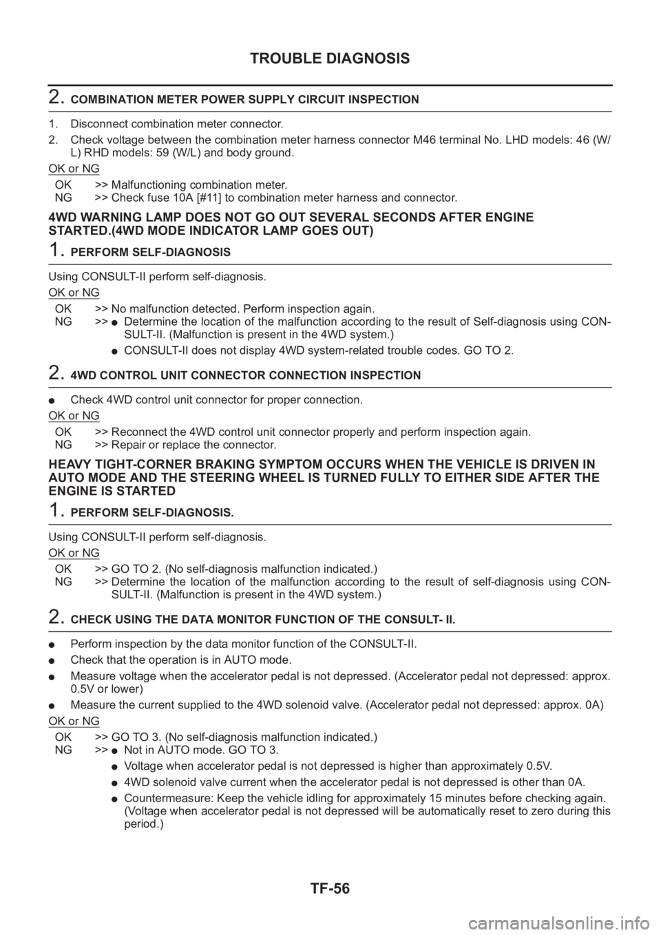
2. COMBINATION METER POWER SUPPLY CIRCUIT INSPECTION
1. Disconnect combination meter connector.
2. Check voltage between the combination meter harness connector M46 terminal No. LHD models: 46 (W/
L) RHD models: 59 (W/L) and body ground.
OK or NG
OK >> Malfunctioning combination meter.
NG >> Check fuse 10A [#11] to combination meter harness and connector.
4WD WARNING LAMP DOES NOT GO OUT SEVERAL SECONDS AFTER ENGINE
STARTED.(4WD MODE INDICATOR LAMP GOES OUT)
1. PERFORM SELF-DIAGNOSIS
Using CONSULT-II perform self-diagnosis.
OK or NG
OK >> No malfunction detected. Perform inspection again.
NG >>
●Determine the location of the malfunction according to the result of Self-diagnosis using CON-
SULT-II. (Malfunction is present in the 4WD system.)
●CONSULT-II does not display 4WD system-related trouble codes. GO TO 2.
2. 4WD CONTROL UNIT CONNECTOR CONNECTION INSPECTION
●Check 4WD control unit connector for proper connection.
OK or NG
OK >> Reconnect the 4WD control unit connector properly and perform inspection again.
NG >> Repair or replace the connector.
HEAVY TIGHT-CORNER BRAKING SYMPTOM OCCURS WHEN THE VEHICLE IS DRIVEN IN
AUTO MODE AND THE STEERING WHEEL IS TURNED FULLY TO EITHER SIDE AFTER THE
ENGINE IS STARTED
1. PERFORM SELF-DIAGNOSIS.
Using CONSULT-II perform self-diagnosis.
OK or NG
OK >> GO TO 2. (No self-diagnosis malfunction indicated.)
NG >> Determine the location of the malfunction according to the result of self-diagnosis using CON-
SULT-II. (Malfunction is present in the 4WD system.)
2. CHECK USING THE DATA MONITOR FUNCTION OF THE CONSULT- II.
●Perform inspection by the data monitor function of the CONSULT-II.
●Check that the operation is in AUTO mode.
●Measure voltage when the accelerator pedal is not depressed. (Accelerator pedal not depressed: approx.
0.5V or lower)
●Measure the current supplied to the 4WD solenoid valve. (Accelerator pedal not depressed: approx. 0A)
OK or NG
OK >> GO TO 3. (No self-diagnosis malfunction indicated.)
NG >>
●Not in AUTO mode. GO TO 3.
●Voltage when accelerator pedal is not depressed is higher than approximately 0.5V.
●4WD solenoid valve current when the accelerator pedal is not depressed is other than 0A.
●Countermeasure: Keep the vehicle idling for approximately 15 minutes before checking again.
(Voltage when accelerator pedal is not depressed will be automatically reset to zero during this
period.)
Page 2707 of 3833
FSU-1
FRONT SUSPENSION
E SUSPENSION
CONTENTS
C
D
F
G
H
I
J
K
L
M
SECTION
A
B
FSU
FRONT SUSPENSION
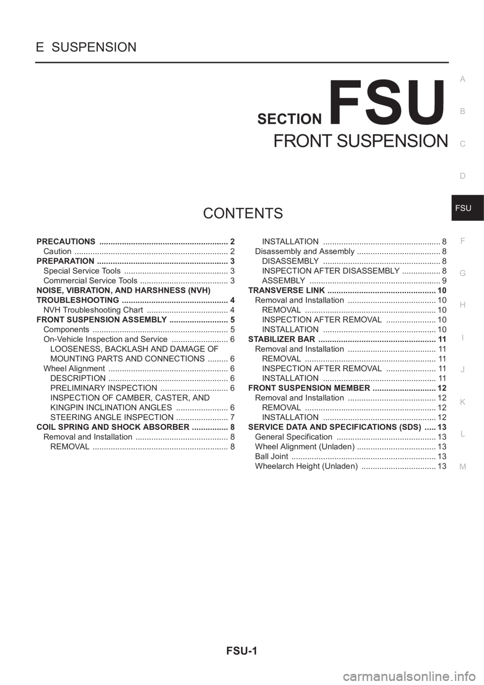
PRECAUTIONS .......................................................... 2
Caution ..................................................................... 2
PREPARATION ........................................................... 3
Special Service Tools ............................................... 3
Commercial Service Tools ........................................ 3
NOISE, VIBRATION, AND HARSHNESS (NVH)
TROUBLESHOOTING ................................................ 4
NVH Troubleshooting Chart ..................................... 4
FRONT SUSPENSION ASSEMBLY ........................... 5
Components ............................................................. 5
On-Vehicle Inspection and Service .......................... 6
LOOSENESS, BACKLASH AND DAMAGE OF
MOUNTING PARTS AND CONNECTIONS .......... 6
Wheel Alignment ...................................................... 6
DESCRIPTION ...................................................... 6
PRELIMINARY INSPECTION ............................... 6
INSPECTION OF CAMBER, CASTER, AND
KINGPIN INCLINATION ANGLES ........................ 6
STEERING ANGLE INSPECTION ........................ 7
COIL SPRING AND SHOCK ABSORBER ................. 8
Removal and Installation .......................................... 8
REMOVAL ............................................................. 8INSTALLATION ..................................................... 8
Disassembly and Assembly ...................................... 8
DISASSEMBLY ..................................................... 8
INSPECTION AFTER DISASSEMBLY .................. 8
ASSEMBLY ........................................................... 9
TRANSVERSE LINK ................................................. 10
Removal and Installation ........................................ 10
REMOVAL ........................................................... 10
INSPECTION AFTER REMOVAL ....................... 10
INSTALLATION ................................................... 10
STABILIZER BAR ..................................................... 11
Removal and Installation ........................................ 11
REMOVAL ........................................................... 11
INSPECTION AFTER REMOVAL ....................... 11
INSTALLATION ................................................... 11
FRONT SUSPENSION MEMBER ............................. 12
Removal and Installation ........................................ 12
REMOVAL ........................................................... 12
INSTALLATION ................................................... 12
SERVICE DATA AND SPECIFICATIONS (SDS) ...... 13
General Specification ............................................. 13
Wheel Alignment (Unladen) .................................... 13
Ball Joint ................................................................. 13
Wheelarch Height (Unladen) .................................. 13
Page 2710 of 3833
FSU-4
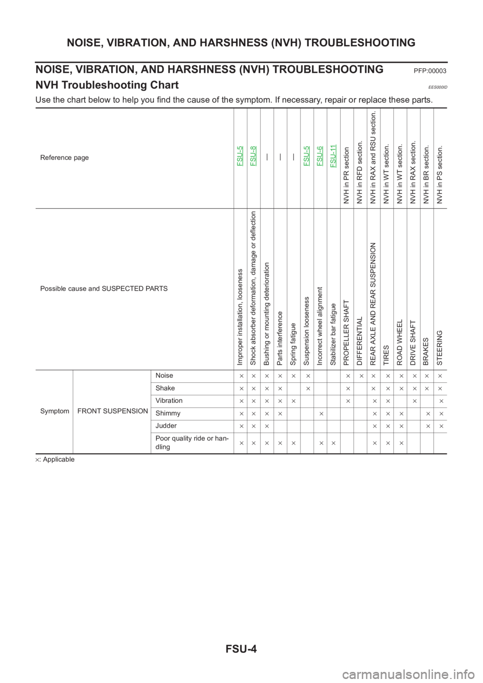
NOISE, VIBRATION, AND HARSHNESS (NVH) TROUBLESHOOTING
NOISE, VIBRATION, AND HARSHNESS (NVH) TROUBLESHOOTING
PFP:00003
NVH Troubleshooting ChartEES000ID
Use the chart below to help you find the cause of the symptom. If necessary, repair or replace these parts.
×: ApplicableReference page
FSU-5FSU-8—
—
—
FSU-5FSU-6FSU-11
NVH in PR section
NVH in RFD section.
NVH in RAX and RSU section.
NVH in WT section.
NVH in WT section.
NVH in RAX section.
NVH in BR section.
NVH in PS section.
Possible cause and SUSPECTED PARTS
Improper installation, looseness
Shock absorber deformation, damage or deflection
Bushing or mounting deterioration
Parts interference
Spring fatigue
Suspension looseness
Incorrect wheel alignment
Stabilizer bar fatigue
PROPELLER SHAFT
DIFFERENTIAL
REAR AXLE AND REAR SUSPENSION
TIRES
ROAD WHEEL
DRIVE SHAFT
BRAKES
STEERING
Symptom FRONT SUSPENSIONNoise××××× × ××× ×××××
Shake×××× × × × ×××××
Vibration××××× × ×× × ×
Shimmy×××× × ××× ××
Judder××× ××× ××
Poor quality ride or han-
dling×× × × × ×× × × ×
Page 2712 of 3833
FSU-6
FRONT SUSPENSION ASSEMBLY
On-Vehicle Inspection and Service
EES00072
LOOSENESS, BACKLASH AND DAMAGE OF MOUNTING PARTS AND CONNECTIONS
Lift vehicle and inspect the following:
●Check mounting point of each component for looseness, backlash and damage.
●Check lower ball joint end play.
1. Attach a dial gauge so that the contact rests on the brake caliper.
2. Set front wheels in a straight-ahead position. Do not depress brake pedal.
3. Measure axial endplay by placing an iron pry bar or something similar between transverse link and steer-
ing knuckle.
CAUTION:
Be careful not to damage ball joint boot.
4. If axial endplay is outside the standard, remove transverse link and check lower ball joint.
Wheel AlignmentEES00073
DESCRIPTION
●Measure wheel alignment under unladen conditions. “Unladen conditions” means that fuel, coolant, and
lubricant are full. However, spare tire, jack, and hand tools should be unloaded.
PRELIMINARY INSPECTION
1. Check the tires for improper air pressure and wear.
2. Check road wheels for runout.
3. Check wheel bearing axial endplay.
4. Check lower ball joint axial endplay.
5. Check strut operation.
6. Check each mounting point of axle and suspension for looseness and deformation.
7. Check each link and arm for cracks, deformation, and other damage.
8. Check the vehicle posture.
INSPECTION OF CAMBER, CASTER, AND KINGPIN INCLINATION ANGLES
● Camber, caster, and kingpin inclination angles cannot be adjusted.
●Before inspection, mount front wheels onto turning radius gauge. Mount rear wheels onto a stand that has
same height so the vehicle will remain horizontal.
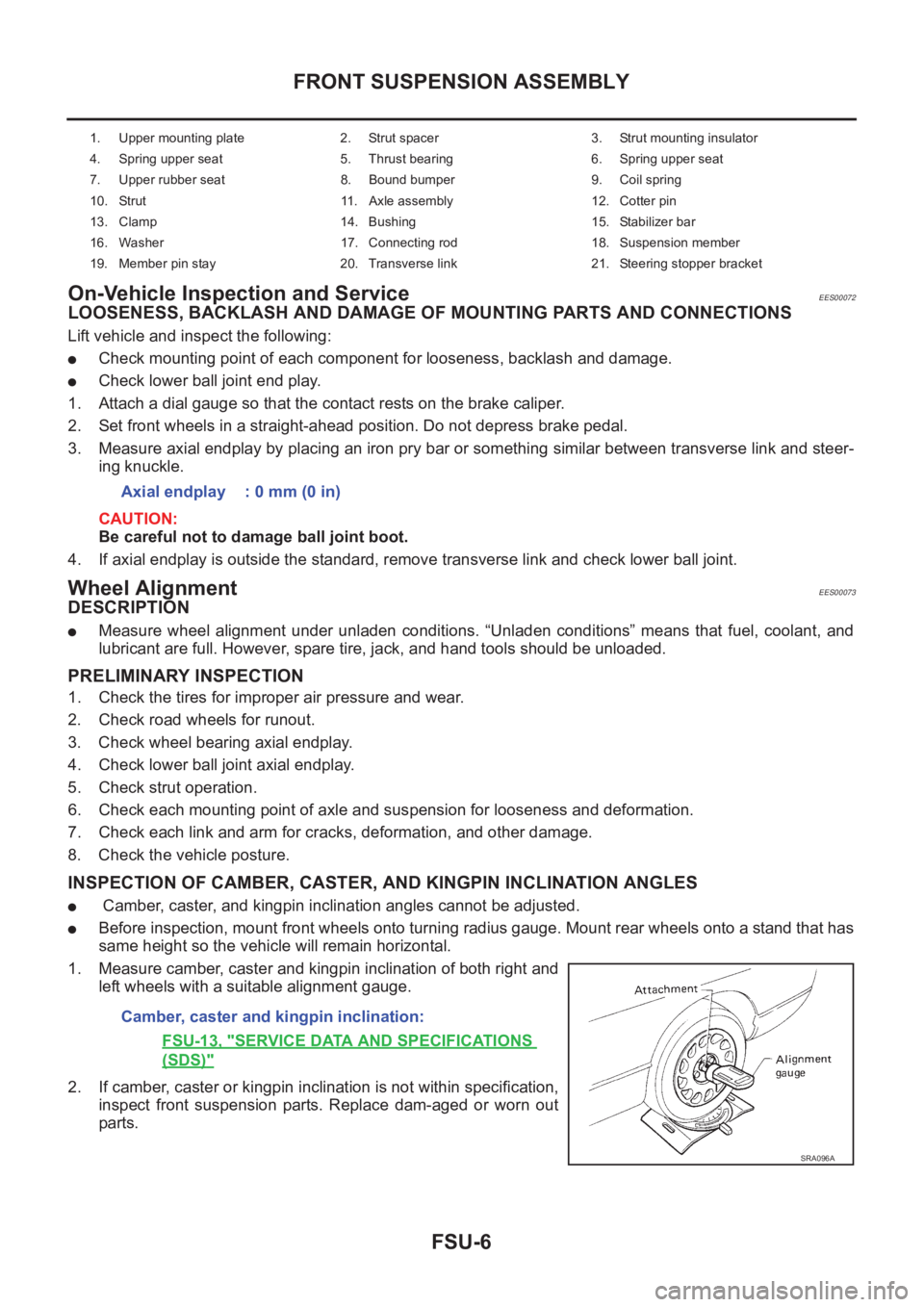
1. Measure camber, caster and kingpin inclination of both right and
left wheels with a suitable alignment gauge.
2. If camber, caster or kingpin inclination is not within specification,
inspect front suspension parts. Replace dam-aged or worn out
parts.
1. Upper mounting plate 2. Strut spacer 3. Strut mounting insulator
4. Spring upper seat 5. Thrust bearing 6. Spring upper seat
7. Upper rubber seat 8. Bound bumper 9. Coil spring
10. Strut 11. Axle assembly 12. Cotter pin
13. Clamp 14. Bushing 15. Stabilizer bar
16. Washer 17. Connecting rod 18. Suspension member
19. Member pin stay 20. Transverse link 21. Steering stopper bracket
Axial endplay : 0 mm (0 in)
Camber, caster and kingpin inclination:
FSU-13, "
SERVICE DATA AND SPECIFICATIONS
(SDS)"
SRA096A
Page 2713 of 3833
FRONT SUSPENSION ASSEMBLY
FSU-7
C
D
F
G
H
I
J
K
L
MA
B
FSU
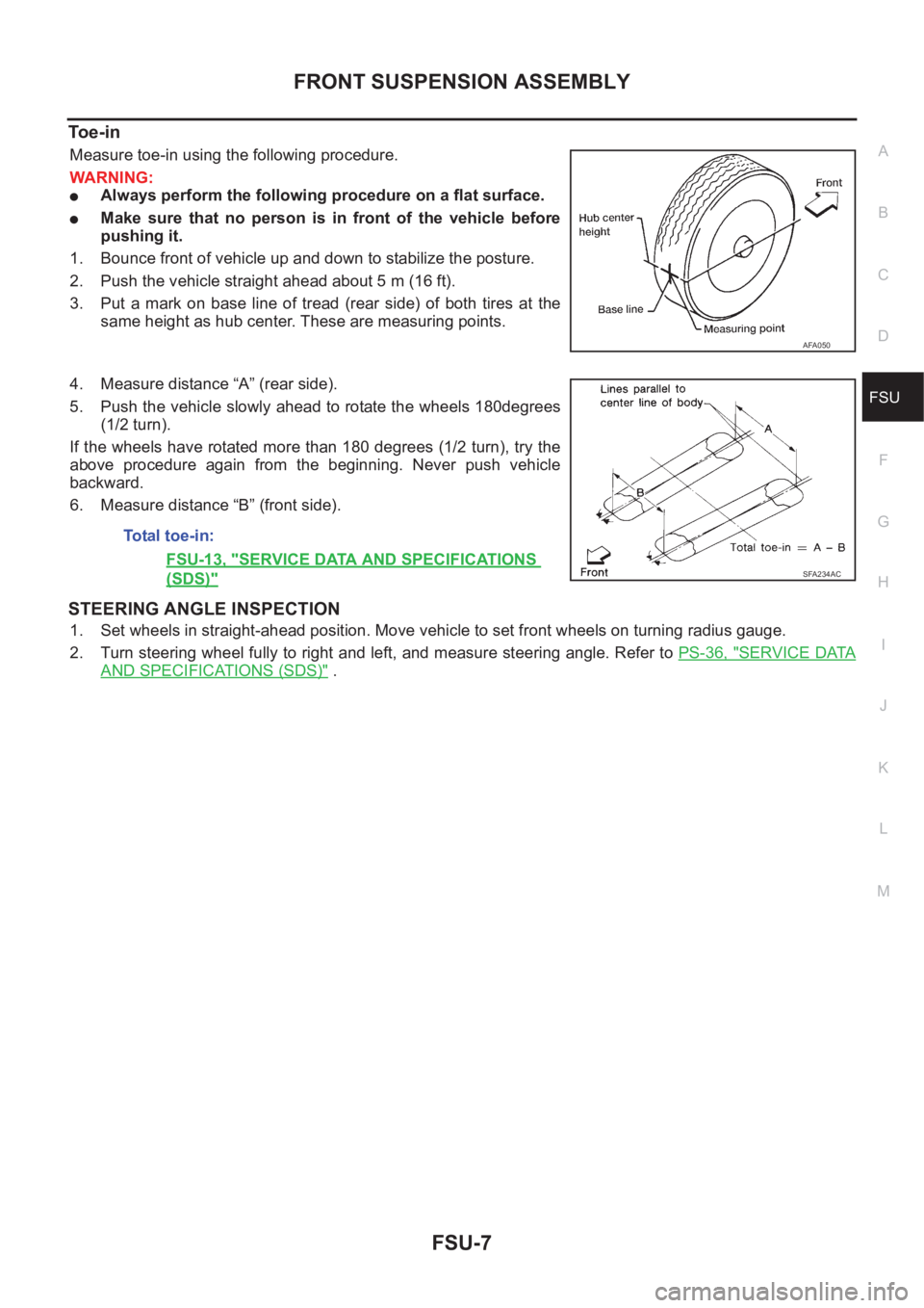
To e - i n
Measure toe-in using the following procedure.
WARNING:
●Always perform the following procedure on a flat surface.
●Make sure that no person is in front of the vehicle before
pushing it.
1. Bounce front of vehicle up and down to stabilize the posture.
2. Push the vehicle straight ahead about 5 m (16 ft).
3. Put a mark on base line of tread (rear side) of both tires at the
same height as hub center. These are measuring points.
4. Measure distance “A” (rear side).
5. Push the vehicle slowly ahead to rotate the wheels 180degrees
(1/2 turn).
If the wheels have rotated more than 180 degrees (1/2 turn), try the
above procedure again from the beginning. Never push vehicle
backward.
6. Measure distance “B” (front side).
STEERING ANGLE INSPECTION
1. Set wheels in straight-ahead position. Move vehicle to set front wheels on turning radius gauge.
2. Turn steering wheel fully to right and left, and measure steering angle. Refer to PS-36, "
SERVICE DATA
AND SPECIFICATIONS (SDS)" .
AFA050
Total toe-in:
FSU-13, "
SERVICE DATA AND SPECIFICATIONS
(SDS)"SFA234AC
Page 2714 of 3833
FSU-8
COIL SPRING AND SHOCK ABSORBER
COIL SPRING AND SHOCK ABSORBER
PFP:54302
Removal and InstallationEES00074
REMOVAL
1. Remove tires. Remove brake caliper and hung it aside.
CAUTION:
Avoid depressing brake pedal with brake caliper removed.
2. Remove electrical wires of ABS wheel speed sensor from strut.
3. Remove brake hose lock plate.
4. Remove mounting bolts and nuts securing steering knuckle to strut.
5. Remove mounting nuts on upper mounting plate and remove upper mounting plate and strut from vehicle.
INSTALLATION
●Refer to FSU-5, "Components" in “Front Suspension Assembly” for tightening torque. Tighten in the
reverse order of removal.
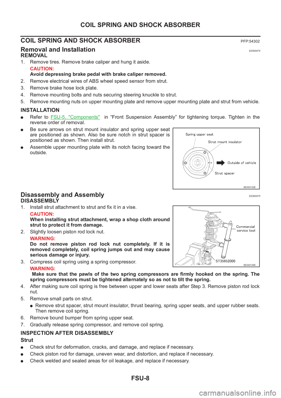
●Be sure arrows on strut mount insulator and spring upper seat
are positioned as shown. Also be sure notch in strut spacer is
positioned as shown. Then install strut.
●Assemble upper mounting plate with its notch facing toward the
outside.
Disassembly and AssemblyEES00075
DISASSEMBLY
1. Install strut attachment to strut and fix it in a vise.
CAUTION:
When installing strut attachment, wrap a shop cloth around
strut to protect it from damage.
2. Slightly loosen piston rod lock nut.
WARNING:
Do not remove piston rod lock nut completely. If it is
removed completely, coil spring jumps out and may cause
serious damage or injury.
3. Compress coil spring using a spring compressor.
WARNING:
Make sure that the pawls of the two spring compressors are firmly hooked on the spring. The
spring compressors must be tightened alternately so as not to tilt the spring.
4. After making sure coil spring is free between upper and lower seats after Step 3. Remove piston rod lock
nut.
5. Remove small parts on strut.
●Remove strut spacer, strut mount insulator, thrust bearing, spring upper seats, and upper rubber seats.
Then remove coil spring.
6. Remove bound bumper from spring upper seat.
7. Gradually release spring compressor, and remove coil spring.
INSPECTION AFTER DISASSEMBLY
Strut
●Check strut for deformation, cracks, and damage, and replace if necessary.
●Check piston rod for damage, uneven wear, and distortion, and replace if necessary.
●Check welded and sealed areas for oil leakage, and replace if necessary.
SEIA0123E
SEIA0124E
Page 2716 of 3833
FSU-10
TRANSVERSE LINK
TRANSVERSE LINK
PFP:54500
Removal and InstallationEES00076
REMOVAL
1. Remove steering knuckle from transverse link. Refer toFAX-7, "REMOVAL" .
2. Remove mounting nuts and washers on lower portion of stabilizer connecting rod.
3. Slightly loosen transverse link mounting bolts.
4. Remove transverse link mounting bolts and nuts, and remove transverse link from suspension member.
INSPECTION AFTER REMOVAL
Visual Inspection
Check transverse link and bushing for deformation, cracks, and other damage. Replace the entire transverse
link assembly if cracks, deformation or any other damage is found.
Ball Joint Inspection
CAUTION:
Before measurement, move the ball joint at least ten times by hand to check for smooth movement.
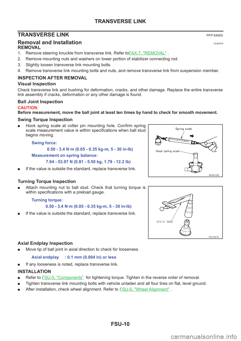
Swing Torque Inspection
●Hook spring scale at cotter pin mounting hole. Confirm spring
scale measurement value is within specifications when ball stud
begins moving.
●If the value is outside the standard, replace transverse link.
Turning Torque Inspection
●Attach mounting nut to ball stud. Check that turning torque is
within specifications with a preload gauge.
●If the value is outside the standard, replace transverse link.
Axial Endplay Inspection
●Move tip of ball joint in axial direction to check for looseness.
●If any looseness is noted, replace transverse link.
INSTALLATION
●Refer to FSU-5, "Components" for tightening torque. Tighten in the reverse order of removal.
●Tighten transverse link mounting bolts with vehicle unladen and all four tires on flat, level ground.
●After installation, check wheel alignment. Refer to FSU-6, "Wheel Alignment" . Swing force:
0.50 - 3.4 N·m (0.05 - 0.35 kg-m, 5 - 30 in-lb)
Measurement on spring balance:
7.94 - 53.97 N (0.81 - 5.50 kg, 1.79 - 12.2 lb)
SEIA0122E
Turning torque:
0.50 - 3.4 N·m (0.05 - 0.35 kg-m, 5 - 30 in-lb)
FAC1021D
Axial endplay : 0.1 mm (0.004 in) or less
Page 2718 of 3833
FSU-12
FRONT SUSPENSION MEMBER
FRONT SUSPENSION MEMBER
PFP:54401
Removal and InstallationEES00078
REMOVAL
1. Remove tires. Raise vehicle.
2. Remove mounting nuts on lower portion of stabilizer connecting rod from transverse link.
3. Remove transverse link from suspension member, and move the transverse link outward.
4. Remove front exhaust tube mounting rubber from suspension member.
5. Support engine or transmission with a transmission jack.
6. Remove center member from vehicle. Refer to TF-11, "
TRANSFER ASSEMBLY"
7. Remove steering gear mounting bolts. Remove steering gear and power steering tube bracket from sus-
pension member.
8. Hang steering gear.
9. Remove rear engine mount insulator from suspension member.
10. Remove body-side mounting bolts from member pin stay.
11. Set a transmission jack under suspension member, and remove suspension member mounting nuts.
12. Slowly lower transmission jack to remove suspension member from vehicle.
INSTALLATION
●Refer to FSU-5, "Components" for tightening torque in the reverse order of removal.
●After installation, perform final tightening of each part under unladen conditions with tires on ground.
Check wheel alignment. Refer to FSU-6, "
Wheel Alignment" .