2001 NISSAN X-TRAIL coolant level
[x] Cancel search: coolant levelPage 1867 of 3833
![NISSAN X-TRAIL 2001 Service Repair Manual DTC P1217 OVERHEAT (COOLING SYSTEM)
EC-1517
[YD]
C
D
E
F
G
H
I
J
K
L
MA
EC
5.DETECT MALFUNCTIONING PART
Check the following.
●Harness connectors E64, F5
●Harness for open or short between cooling NISSAN X-TRAIL 2001 Service Repair Manual DTC P1217 OVERHEAT (COOLING SYSTEM)
EC-1517
[YD]
C
D
E
F
G
H
I
J
K
L
MA
EC
5.DETECT MALFUNCTIONING PART
Check the following.
●Harness connectors E64, F5
●Harness for open or short between cooling](/manual-img/5/57405/w960_57405-1866.png)
DTC P1217 OVERHEAT (COOLING SYSTEM)
EC-1517
[YD]
C
D
E
F
G
H
I
J
K
L
MA
EC
5.DETECT MALFUNCTIONING PART
Check the following.
●Harness connectors E64, F5
●Harness for open or short between cooling fan relays-2 and -3 and ECM
>> Repair open circuit or short to ground or short to power in harness or connectors.
6.CHECK COOLING FAN RELAYS-2 AND -3
Refer to EC-1518, "
Component Inspection" .
OK or NG
OK >> GO TO 7.
NG >> Replace cooling fan relays.
7.CHECK COOLING FAN MOTORS
Refer to EC-1518, "
Component Inspection" .
OK or NG
OK >> GO TO 8.
NG >> Replace cooling fan motors.
8.CHECK INTERMITTENT INCIDENT
Perform EC-1441, "
TROUBLE DIAGNOSIS FOR INTERMITTENT INCIDENT" .
>>INSPECTION END
Main 12 Causes of OverheatingEBS004QY
Engine Step Inspection item Equipment Condition Reference page
OFF 1
●Blocked radiator
●Blocked radiator grille
●Blocked bumper
●Visual No blocking —
2
●Coolant mixture●Coolant tester 50 - 50% coolant mixture See MA-16, "RECOM-
MENDED FLUIDS AND
LUBRICANTS" .
3
●Coolant level●Visual Coolant up to MAX level
in reservoir tank and radi-
ator filler neckSee MA-27, "Changing
Engine Coolant" .
4
●Radiator cap●Pressure tester 78 - 98 kPa (0.78 - 0.98
ba r, 0.8 - 1.0 kg/cm2 , 11 -
14 psi)See CO-33, "
Checking
Radiator Cap" .
ON*
25●Coolant leaks●Visual No leaks See CO-29, "CHECKING
RADIATOR SYSTEM
FOR LEAKS" .
ON*
26●Thermostat●Touch the upper and
lower radiator hosesBoth hoses should be hot See CO-41, "THERMO-
STAT AND WATER PIP-
ING" .
ON*
17●Cooling fan●CONSULT-II Operating See Trouble Diagnosis for
DTC P1217, EC-1458
.
OFF 8
●Combustion gas leak●Color checker chemi-
cal tester 4 Gas ana-
lyzerNegative —
Page 1868 of 3833
![NISSAN X-TRAIL 2001 Service Repair Manual EC-1518
[YD]
DTC P1217 OVERHEAT (COOLING SYSTEM)
*1: Turn the ignition switch ON.
*2: Engine running at 3,000 rpm for 10 minutes.
*3: Drive at 90 km/h (55 MPH) for 30 minutes and then let idle for 10 NISSAN X-TRAIL 2001 Service Repair Manual EC-1518
[YD]
DTC P1217 OVERHEAT (COOLING SYSTEM)
*1: Turn the ignition switch ON.
*2: Engine running at 3,000 rpm for 10 minutes.
*3: Drive at 90 km/h (55 MPH) for 30 minutes and then let idle for 10](/manual-img/5/57405/w960_57405-1867.png)
EC-1518
[YD]
DTC P1217 OVERHEAT (COOLING SYSTEM)
*1: Turn the ignition switch ON.
*2: Engine running at 3,000 rpm for 10 minutes.
*3: Drive at 90 km/h (55 MPH) for 30 minutes and then let idle for 10 minutes.
*4: After 60 minutes of cool down time.
For more information, refer to CO-25, "
OVERHEATING CAUSE ANALYSIS" .
Component InspectionEBS004QZ
COOLING FAN RELAY-1, -2 AND -3
Check continuity between terminals 3 and 5, 6 and 7 under the fol-
lowing conditions.
COOLING FAN MOTOR-1 AND -2
Supply battery voltage between the following terminals and check
operation.
ON*39●Coolant temperature
gauge●Visual Gauge less than 3/4
when driving—
●Coolant overflow to
reservoir tank●Visual No overflow during driv-
ing and idlingSeeMA-27, "Changing
Engine Coolant" .
OFF*
410●Coolant return from
reservoir tank to radia-
tor●Visual Should be initial level in
reservoir tankSeeMA-28, "REFILLING
ENGINE COOLANT" .
OFF 11
●Cylinder head●Straight gauge feeler
gauge0.1mm (0.004 in) Maxi-
mum distortion (warping)SeeEM-182, "CYLIN-
DER HEAD" .
12
●Cylinder block and pis-
tons●Visual No scuffing on cylinder
walls or pistonSeeEM-197, "CYLIN-
DER BLOCK" . Engine Step Inspection item Equipment Condition Reference page
Conditions Continuity
12V direct current supply between ter-
minals 1 and 2Ye s
No current supply No
SEF745U
SpeedTe r m i n a l s
(+) (–)
Cooling fan motor-1Low 1 4
High 1, 2 3, 4
Cooling fan motor-2Low 1 4
High 1, 2 3, 4
PBIB0423E
Page 2708 of 3833
FSU-2
PRECAUTIONS
PRECAUTIONS
PFP:00001
CautionEES0006Z
●When installing rubber bushings, final tightening must be carried out under unladen conditions with tires
on flat, level ground. Oil will shorten the life of rubber bushings. Be sure to wipe off any spilled oil.
●“Unladen condition” means that fuel, coolant and lubricant are full and ready for drive. However, spare tire,
jack, and hand tools should be unloaded.
●After installing the removed suspension parts, always check wheel alignment and adjust if necessary.
●Replace the caulking nut with a new one. Install a new nut without wiping the oil off before tightening.
Page 3496 of 3833
LT-6
HEADLAMP
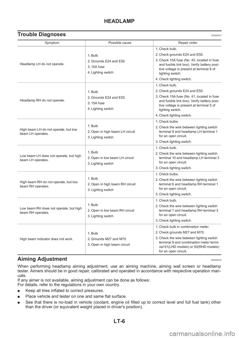
Trouble Diagnoses
EKS003CF
Aiming Adjustment EKS003CG
When performing headlamp aiming adjustment, use an aiming machine, aiming wall screen or headlamp
tester. Aimers should be in good repair, calibrated and operated in accordance with respective operation man-
uals.
If any aimer is not available, aiming adjustment can be done as follows:
For details, refer to the regulations in your own country.
●Keep all tires inflated to correct pressures.
●Place vehicle and tester on one and same flat surface.
●See that there is no-load in vehicle (coolant, engine oil filled up to correct level and full fuel tank) other
than the driver (or equivalent weight placed in driver's position).
Symptom Possible cause Repair order
Headlamp LH do not operate.1. Bulb
2. Grounds E24 and E50
3. 15A fuse
4. Lighting switch1. Check bulb.
2. Check grounds E24 and E50.
3. Check 15A fuse (No. 40, located in fuse
and fusible link box). Verify battery posi-
tive voltage is present at terminal 8 of
lighting switch.
4. Check lighting switch.
Headlamp RH do not operate.1. Bulb
2. Grounds E24 and E50
3. 15A fuse
4. Lighting switch1. Check bulb.
2. Check grounds E24 and E50.
3. Check 15A fuse (No. 41, located in fuse
and fusible link box). Verify battery posi-
tive voltage is present at terminal 5 of
lighting switch.
4. Check lighting switch.
High beam LH do not operate, but low
beam LH operates.1. Bulb
2. Open in high beam LH circuit
3. Lighting switch1. Check bulbs.
2. Check the wire between lighting switch
terminal 9 and headlamp LH terminal 1
for an open circuit.
3. Check lighting switch.
Low beam LH does not operate, but high
beam LH operates.1. Bulb
2. Open in low beam LH circuit
3. Lighting switch1. Check bulb.
2. Check the wire between lighting switch
terminal 10 and headlamp LH terminal 3
for an open circuit.
3. Check lighting switch.
High beam RH do not operate, but low
beam RH operates.1. Bulb
2. Open in high beam RH circuit
3. Lighting switch1. Check bulbs.
2. Check the wire between lighting switch
terminal 6 and headlamp RH terminal 1
for an open circuit.
3. Check lighting switch.
Low beam RH does not operate, but high
beam RH operates.1. Bulb
2. Open in low beam RH circuit
3. Lighting switch1. Check bulb.
2. Check the wire between lighting switch
terminal 7 and headlamp RH terminal 3
for an open circuit.
3. Check lighting switch.
High beam indicator does not work.1. Bulb
2. Grounds M27 and M70
3. Open in high beam circuit1. Check bulb in combination meter.
2. Check grounds M27 and M70.
3. Check the wire between lighting switch
terminal 9 and combination meter termi-
nal 61(LHD models) or 50(RHD models)
for an open circuit.
Page 3563 of 3833
COMBINATION METERS (LHD MODELS)
DI-5
C
D
E
F
G
H
I
J
L
MA
B
DI
Diesel engine models
The water temperature gauge indicates the engine coolant temperature. The reading on the gauge is based
on the resistance of the thermal transmitter.
As the temperature of the coolant increases, the resistance of the thermal transmitter decreases. A variable
ground is supplied to terminal 55 of the combination meter for the water temperature gauge. The needle on
the gauge moves from “C” to “H”.
TACHOMETER
The tachometer indicates engine speed in revolutions per minute (rpm).
The tachometer is regulated by a signal
●from terminal 36 (Gasoline engine models) or D1 (Diesel engine models) of the ECM
●to combination meter terminal 54 for the tachometer.
FUEL GAUGE
The fuel gauge indicates the approximate fuel level in the fuel tank.
The fuel gauge is regulated by a variable ground signal supplied
●from body grounds, B8 and B18
●through terminals 4 and 1 of the fuel level sensor unit and
●through terminals 1 and 3 of the Sub fuel level sensor unit
●to combination meter terminal 51 for the fuel gauge.
SPEEDOMETER
The combination meter provides a voltage signal to the vehicle speed signal from 4WD/ABS control unit (with-
out ESP) or 4WD control unit (with ESP).
The voltage is supplied
●from combination meter terminal 52 for the speedometer
●to terminal 20 of 4WD control unit (with ESP) or 4WD/ABS control unit (without ESP).
The speedometer converts the voltage into the vehicle speed displayed.
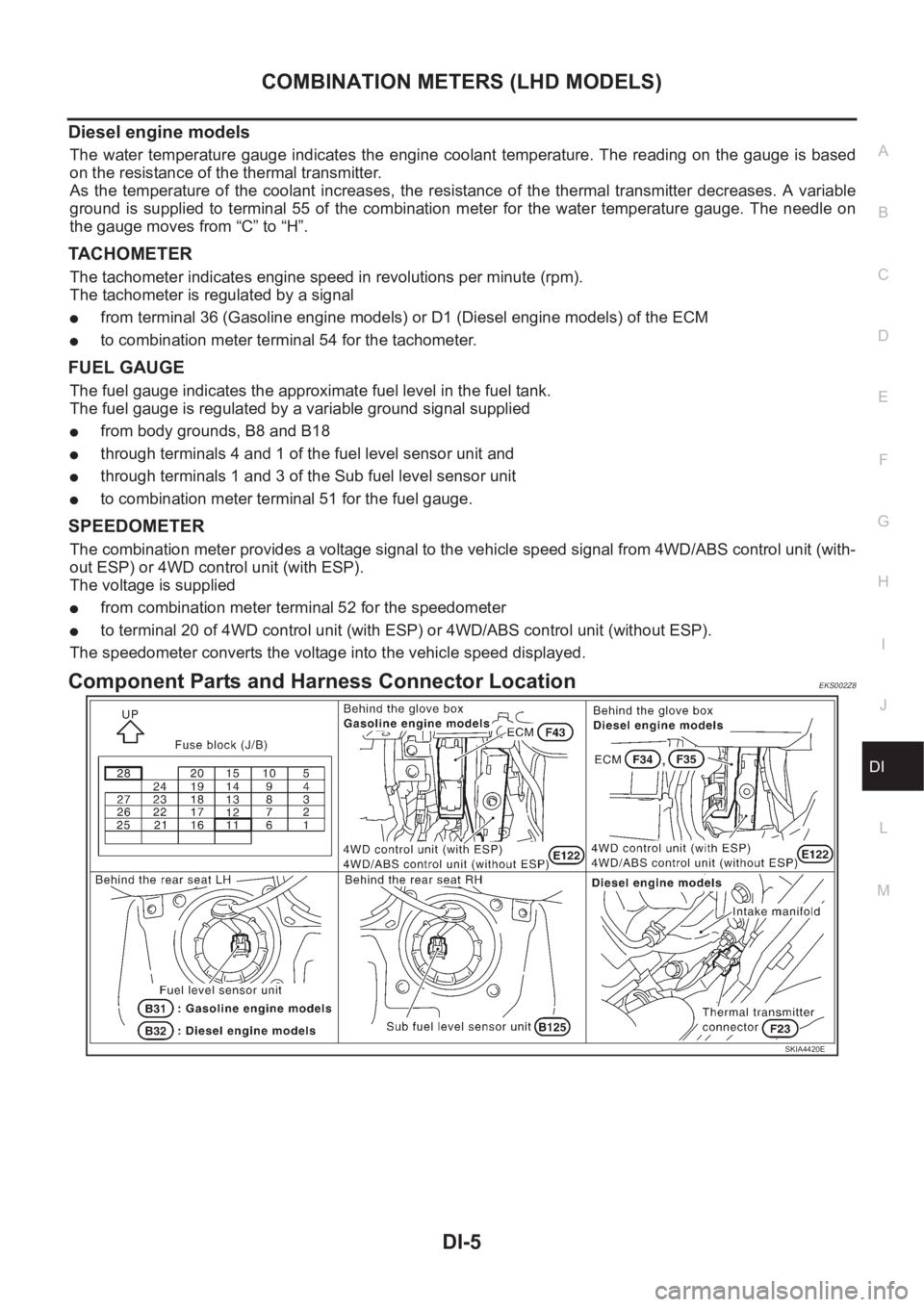
Component Parts and Harness Connector LocationEKS002Z8
SKIA4420E
Page 3583 of 3833
COMBINATION METERS (RHD MODELS)
DI-25
C
D
E
F
G
H
I
J
L
MA
B
DI
Diesel engine models
The water temperature gauge indicates the engine coolant temperature. The reading on the gauge is based
on the resistance of the thermal transmitter.
As the temperature of the coolant increases, the resistance of the thermal transmitter decreases. A variable
ground is supplied to terminal 66 of the combination meter for the water temperature gauge. The needle on
the gauge moves from “C” to “H”.
TACHOMETER
The tachometer indicates engine speed in revolutions per minute (rpm).
The tachometer is regulated by a signal
●from terminal 36 (Gasoline engine models) or D1 (Diesel engine models) of the ECM
●to combination meter terminal 41 for the tachometer.
FUEL GAUGE
The fuel gauge indicates the approximate fuel level in the fuel tank.
The fuel gauge is regulated by a variable ground signal supplied
●from body grounds, B107 and B119
●through terminals 4 and 1 of the fuel level sensor unit and
●through terminals 1 and 3 of the sub fuel level sensor unit
●to combination meter terminal 40 for the fuel gauge.
SPEEDOMETER
The combination meter provides a voltage signal to the vehicle speed signal from 4WD/ABS control unit (with-
out ESP) or 4WD control unit (with ESP).
The voltage is supplied
●from combination meter terminal 42 for the speedometer
●to terminal 20 of 4WD control unit (with ESP) or 4WD/ABS control unit (without ESP).
The speedometer converts the voltage into the vehicle speed displayed.
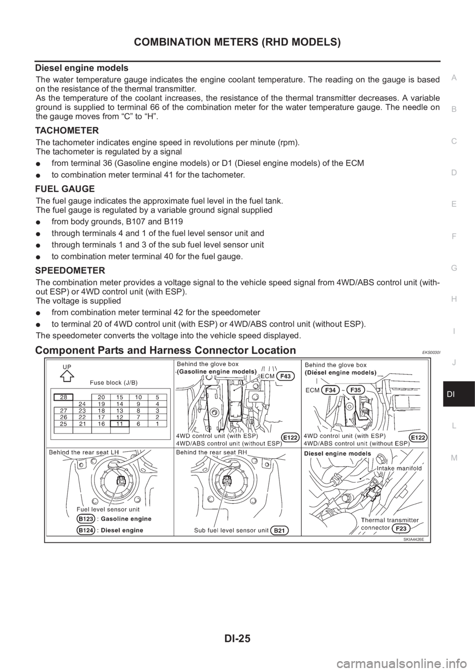
Component Parts and Harness Connector LocationEKS0030I
SKIA4426E
Page 3782 of 3833

MA-2
Changing Engine Oil ............................................ ... 32
Changing Oil Filter .................................................. 33
REMOVAL ........................................................... 33
INSTALLATION .................................................... 34
Draining Water ........................................................ 34
CHASSIS AND BODY MAINTENANCE ................... 35
Checking Exhaust System ...................................... 35
Checking Clutch Fluid Level and Leaks ................. 35
Checking Clutch System ........................................ 35
Checking M/T Oil .................................................... 35
Changing M/T Oil .................................................... 35
Checking A/T Fluid ................................................. 36
Changing A/T Fluid ................................................. 36
Checking Transfer Oil ............................................. 37
Changing Transfer Oil .......................................... ... 37
Checking Propeller Shaft ........................................ 37
Checking Differential Gear Oil ................................ 38
Changing Differential Gear Oil ................................ 38
Balancing Wheels ................................................... 38
Rotation .................................................................. 38
Checking Brake Fluid Level and Leaks .................. 39
Checking Brake Lines and Cables ......................... 39
Changing Brake Fluid ............................................. 39
Checking Disc Brake .............................................. 39
ROTOR ................................................................ 39
CALIPER ............................................................. 40PAD ...................................................................... 40
Checking Steering Gear and Linkage ..................... 40
STEERING GEAR ............................................... 40
STEERING LINKAGE .......................................... 40
Checking Power Steering Fluid and Lines .............. 40
Axle and Suspension Parts ..................................... 41
Drive Shaft .............................................................. 41
Lubricating Locks, Hinges and Hood Latches ......... 41
Checking Seat Belts, Buckles, Retractors, Anchors
and Adjusters .......................................................... 42
Checking Body Corrosion ....................................... 42
HEMMED PANELS .............................................. 42
PANEL JOINT ...................................................... 42
PANEL EDGE ...................................................... 42
PARTS CONTACT ............................................... 42
PROTECTORS .................................................... 42
ANTI-CORROSION MATERIALS ........................ 42
DRAIN HOLES ..................................................... 42
SERVICE DATA AND SPECIFICATIONS (SDS) ...... 43
Standard and Limit .................................................. 43
BELT DEFLECTION AND TENSION ................... 43
RADIATOR ........................................................... 43
ENGINE COOLANT CAPACITY .......................... 43
ENGINE OIL CAPACITY ...................................... 43
SPARK PLUG ...................................................... 43
Page 3784 of 3833
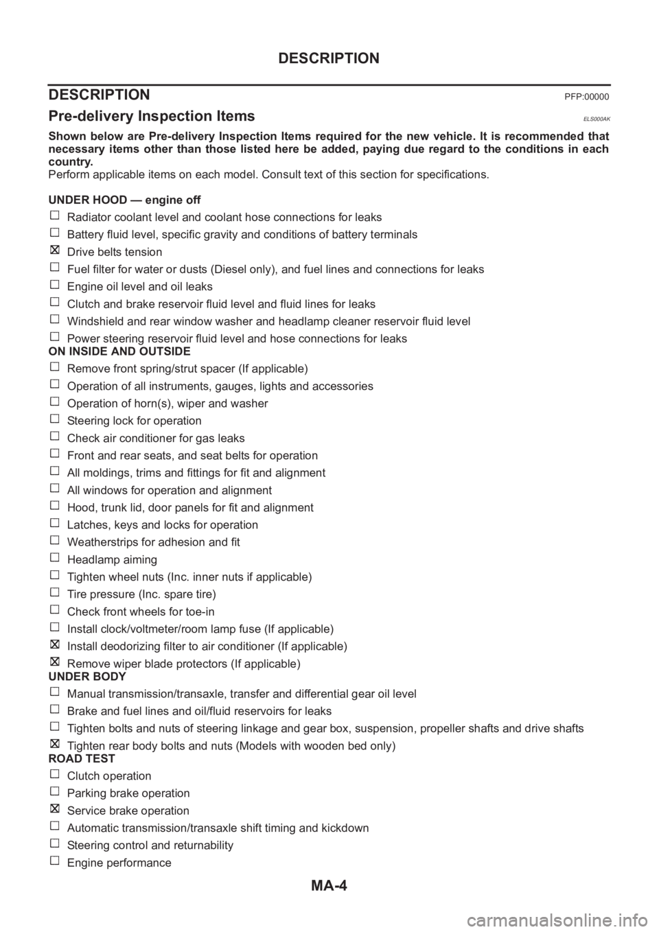
MA-4
DESCRIPTION
DESCRIPTION
PFP:00000
Pre-delivery Inspection ItemsELS000AK
Shown below are Pre-delivery Inspection Items required for the new vehicle. It is recommended that
necessary items other than those listed here be added, paying due regard to the conditions in each
country.
Perform applicable items on each model. Consult text of this section for specifications.
UNDER HOOD — engine off
Radiator coolant level and coolant hose connections for leaks
Battery fluid level, specific gravity and conditions of battery terminals
Drive belts tension
Fuel filter for water or dusts (Diesel only), and fuel lines and connections for leaks
Engine oil level and oil leaks
Clutch and brake reservoir fluid level and fluid lines for leaks
Windshield and rear window washer and headlamp cleaner reservoir fluid level
Power steering reservoir fluid level and hose connections for leaks
ON INSIDE AND OUTSIDE
Remove front spring/strut spacer (If applicable)
Operation of all instruments, gauges, lights and accessories
Operation of horn(s), wiper and washer
Steering lock for operation
Check air conditioner for gas leaks
Front and rear seats, and seat belts for operation
All moldings, trims and fittings for fit and alignment
All windows for operation and alignment
Hood, trunk lid, door panels for fit and alignment
Latches, keys and locks for operation
Weatherstrips for adhesion and fit
Headlamp aiming
Tighten wheel nuts (Inc. inner nuts if applicable)
Tire pressure (Inc. spare tire)
Check front wheels for toe-in
Install clock/voltmeter/room lamp fuse (If applicable)
Install deodorizing filter to air conditioner (If applicable)
Remove wiper blade protectors (If applicable)
UNDER BODY
Manual transmission/transaxle, transfer and differential gear oil level
Brake and fuel lines and oil/fluid reservoirs for leaks
Tighten bolts and nuts of steering linkage and gear box, suspension, propeller shafts and drive shafts
Tighten rear body bolts and nuts (Models with wooden bed only)
ROAD TEST
Clutch operation
Parking brake operation
Service brake operation
Automatic transmission/transaxle shift timing and kickdown
Steering control and returnability
Engine performance