2001 NISSAN X-TRAIL fuel tank removal
[x] Cancel search: fuel tank removalPage 1945 of 3833
![NISSAN X-TRAIL 2001 Service Repair Manual FUEL TANK
FL-21
[YD22DDTi]
C
D
E
F
G
H
I
J
K
L
MA
FL
FUEL TANKPFP:17202
Removal and InstallationEBS00BL3
REMOVAL
WARNING:
Be sure to read “General Precautions” when working on fuel system. Refer t](/manual-img/5/57405/w960_57405-1944.png "NISSAN X-TRAIL 2001 Service Repair Manual FUEL TANK
FL-21
[YD22DDTi]
C
D
E
F
G
H
I
J
K
L
MA
FL
FUEL TANKPFP:17202
Removal and InstallationEBS00BL3
REMOVAL
WARNING:
Be sure to read “General Precautions” when working on fuel system. Refer t")
FUEL TANK
FL-21
[YD22DDTi]
C
D
E
F
G
H
I
J
K
L
MA
FL
FUEL TANKPFP:17202
Removal and InstallationEBS00BL3
REMOVAL
WARNING:
Be sure to read “General Precautions” when working on fuel system. Refer to FL-14, "
General Precau-
tions" .
1. Disconnect battery ground cable.
2. Open the fuel filler cap and release the pressure inside the fuel
tank.
3. Remove rear seat bottom.
4. Peel off floor carpet, then remove inspection hole cover.
5. Disconnect the harness connector, fuel feed tube and fuel return
tube.
6. Drain fuel from fuel tank if necessary. For the draining proce-
dure, refer to step 4 in removal of FL-17, "
FUEL LEVEL SEN-
SOR UNIT" .
CAUTION:
For the safety work and to maintain fuel tank gravity at center, drain fuel to the level where fuel
tank weight at left and right becomes equal.
7. Disconnect the quick connector.
●Put mating marks on hoses for correct installation.
8. Remove exhaust center tube and insulator. Refer to EX-2, "
EXHAUST SYSTEM" .
9. Remove propeller shaft, Refer to PR-2, "
REAR PROPELLER SHAFT" .
SBIA0145E
1. Fuel filler cap 2. Grommet 3. Fuel filler tube
4. Vent hose 5. Vent tube 6. Fuel tank
7. Fuel filler hose 8. Fuel tank band 9. Fuel tank protector
SBIA0140E
Page 1946 of 3833
![NISSAN X-TRAIL 2001 Service Repair Manual FL-22
[YD22DDTi]
FUEL TANK
10. Using a transmission jack, support the bottom of the rear final
drive.
11. Remove the mounting nuts on the rear suspension member, and
lower the transmission](/manual-img/5/57405/w960_57405-1945.png "NISSAN X-TRAIL 2001 Service Repair Manual FL-22
[YD22DDTi]
FUEL TANK
10. Using a transmission jack, support the bottom of the rear final
drive.
11. Remove the mounting nuts on the rear suspension member, and
lower the transmission")
FL-22
[YD22DDTi]
FUEL TANK
10. Using a transmission jack, support the bottom of the rear final
drive.
11. Remove the mounting nuts on the rear suspension member, and
lower the transmission jack carefully until just before the rear
suspension member is removed from the stud bolts on the vehi-
cle.
12. Disconnect fuel filler hose, EVAP hose and vent hose at fuel
tank side.
For disconnection procedure of the quick connector. Refer to
FL-17, "
FUEL LEVEL SENSOR UNIT" .
13. Remove fuel tank protector.
14. Remove fuel tank band mounting bolts while supporting fuel
tank.
15. Remove fuel tank.
INSTALLATION
●Install in the reverse order of removal paying attention to the following.
●Surely clamp fuel hoses and insert hose to the length below.
●Be sure hose clamp is not positioned on swelled area of fuel tube.
●Tighten fuel hose clamp so that the distance between its lugs becomes to the following.
●Push the mounting band pin to the vehicle side securely.
●Before fixing the fuel tank, temporarily install the fuel filler tube.
CAUTION:
Use genuine fuel filler tube mounting bolts or equivalent. Make sure to tighten them to the speci-
fied torque.
●To connect the quick connector. Refer to FL-17, "FUEL LEVEL SENSOR UNIT" .
INSPECTION AFTER INSTALLATION
Make sure there is no fuel leakage at connections in the following steps.
KBIA0285E
KBIA0286E
KBIA0290E
Fuel filler hose : 35 mm (1.38 in)
The other hose : 25 mm (0.98 in)
Fuel tank side : 5 - 9 mm (0.20 - 0.35 in)
Fuel filler tube side : 7 - 11 mm (0.28 - 0.43 in)
Page 3805 of 3833
ENGINE MAINTENANCE (QR20DE·QR25DE)
MA-25
C
D
E
F
G
H
I
J
K
MA
B
MA
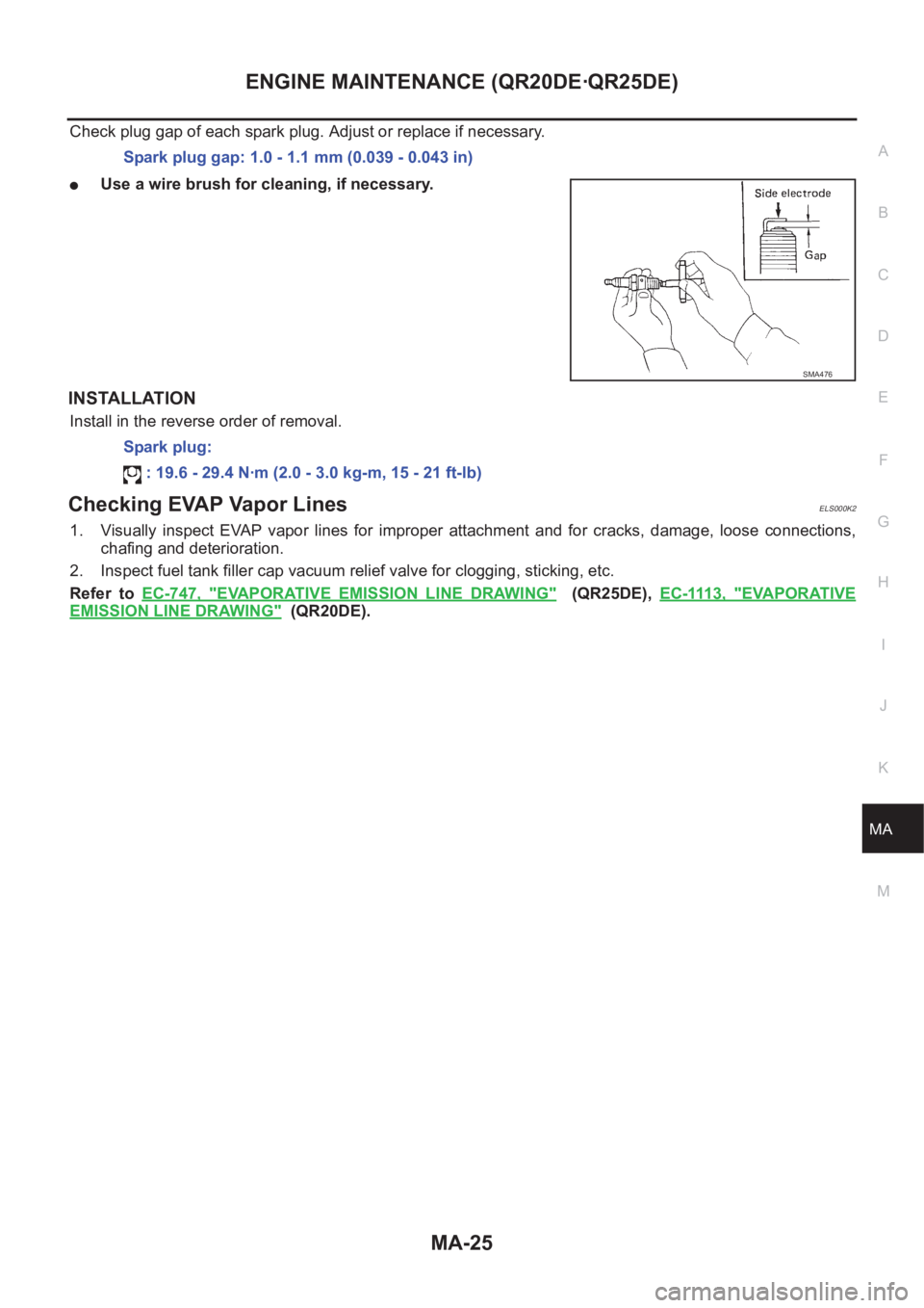
Check plug gap of each spark plug. Adjust or replace if necessary.
●Use a wire brush for cleaning, if necessary.
INSTALLATION
Install in the reverse order of removal.
Checking EVAP Vapor LinesELS000K2
1. Visually inspect EVAP vapor lines for improper attachment and for cracks, damage, loose connections,
chafing and deterioration.
2. Inspect fuel tank filler cap vacuum relief valve for clogging, sticking, etc.
Refer to EC-747, "
EVAPORATIVE EMISSION LINE DRAWING" (QR25DE), EC-1113, "EVAPORATIVE
EMISSION LINE DRAWING" (QR20DE). Spark plug gap: 1.0 - 1.1 mm (0.039 - 0.043 in)
SMA476
Spark plug:
: 19.6 - 29.4 N·m (2.0 - 3.0 kg-m, 15 - 21 ft-lb)
Page 3829 of 3833
IDX-5
A
C
D
E
F
G
H
I
J
K
L B
IDX
ALPHABETICAL INDEX
EC-1368
Fan control amp. ............................. ATC-74,ATC-120
Fan switch ........................................ ATC-30,MTC-17
FIAR - Wiring diagram ................................... EC-1526
Final drive (FF M/T) .............................. MT-21,MT-26
Final drive disassembly ................................... RFD-11
Final drive removal and installation ................. RFD-11
Finisher, interior - See Trim ...................... EI-23,EI-25
Finisher, rear panel .............................................. EI-22
Floor trim ............................................................. EI-28
Flow charts ......................................................... GI-23
Fluid temperature sensor (A/T) ........................ AT-121
Fluorescent leak detector .............................. ATC-147
Flywheel (clutch) ................................................ CL-15
Flywheel runout(QR20DE•QR25DE) ................. EM-97
Flywheel runout(YD22DDTi) ............................ EM-218
Fog lamp, front ................................................... LT-33
Fork rod (M/T) ....................................... MT-20,MT-25
Freeze frame data EC-48,EC-455,EC-780,EC-1142
FRO2 - Wiring diagram .................... EC-672,EC-1321
FRO2/H - Wiring diagram ................ EC-658,EC-1308
Front bumper ......................................................... EI-6
Front disc brake ................................................. BR-21
Front door ............................................................. BL-8
Front Door Trim ................................................... EI-23
Front fog lamp .................................................... LT-33
Front passenger air bag .................................. SRS-35
Front seat ............................................................ SE-7
Front seat belt ...................................................... SB-3
Front seat belt pre-tensioner .... SB-2,SRS-3,SRS-39
Front side air bag ............................................. SRS-36
Front suspension ............................................... FSU-5
Front washer ...................................................... WW-4
Front wiper ......................................................... WW-4
FTS - Wiring diagram .................................... EC-1497
Fuel check valve ................ EC-425,EC-746,EC-1112
Fuel cut control (at no load high engine speed) EC-37,
EC-447
,EC-769,EC-1133,EC-1401
Fuel filler lid ........................................................ BL-75
Fuel filter ........................................................ EC-1404
Fuel filter replacement(QR20DE•QR25DE) .......... FL-4
Fuel filter replacement(YD22DDTi) ....... FL-15,MA-31
Fuel gauge .................................................. DI-4,DI-24
Fuel injection control system ......................... EC-1399
Fuel injection system .......... EC-200,EC-206,EC-934,
EC-940
Fuel injector ................................................... EC-1472
Fuel injector adjustment resistor .................... EC-1525
Fuel injector and fuel tube(QR20DE•QR25DE) . EM-32
Fuel injector and fuel tube(YD22DDTi) ............ EM-144
Fuel leak ........................................................ EC-1529
Fuel line inspection(QR20DE•QR25DE) . FL-3,MA-22
Fuel line inspection(YD22DDTi) ............ FL-14,MA-30
Fuel pressure check EC-42,EC-452,EC-775,EC-1139
Fuel pressure release ........... EC-42,EC-452,EC-775,
EC-1139
Fuel pressure relief valve .............................. EC-1405
Fuel pump ......... EC-405,EC-726,EC-1092,EC-1366
Fuel pump and gauge(QR20DE•QR25DE) .......... FL-4
Fuel system(QR20DE•QR25DE) .......................... FL-3
Fuel system(YD22DDTi) ..................................... FL-14
Fuel tank(QR20DE•QR25DE) ............................... FL-9
Fuel tank(YD22DDTi) ......................................... FL-21
Fuel temperature sensor ................................ EC-1496
Fuse ................................................................... PG-12
Fuse and fusible link box ................................... PG-75
Fusible link ......................................................... PG-12
G
Gear components (M/T) ........................ MT-18
,MT-23
Generator ........................................................... SC-12
Generator - See Alternator ................................ SC-12
Generic scan tool (GST) .................... EC-104,EC-836
Glass ................................................... GW-44,GW-46
GLOW - Wiring diagram ................................ EC-1545
Glow plug ....................................................... EC-1544
Glow plug(YD22DDTi) .................................... EM-138
Glow relay ...................................................... EC-1544
Grille - See Exterior ............................................ EI-11
Ground distribution ............................................ PG-13
G-sensor ............................................................ TF-50
H
H/AIM - Wiring diagram ...................................... LT-15
H/LAMP - Wiring diagram ........................... LT-4,LT-5
H/MIRROR - Wiring diagram ............................ GW-15
Harness connector ............................................. PG-68
Harness layout ................................................... PG-29
Headlamp ............................................................. LT-4
Headlamp aiming control .................................... LT-15
Headlamp leveler - See Headlamp aiming control .......
LT-15
Headlamp washer ............................................ WW-19
Headlining - See Roof trim .................................. EI-29
Heated oxygen sensor 1 .... EC-163,EC-169,EC-178,
EC-295
,EC-301,EC-534,EC-671,EC-899,EC-905,
EC-914
,EC-1023,EC-1029,EC-1229,EC-1320
Heated oxygen sensor 1 heater ........ EC-128,EC-657,
EC-860
,EC-1307
Heated oxygen sensor 2 .... EC-185,EC-192,EC-307,
EC-315
,EC-677,EC-921,EC-927,EC-1035,EC-1042,
EC-1326
Heated oxygen sensor 2 heater ........ EC-133,EC-662,
EC-865
,EC-1312
Heated seat ............................................... SE-3,SE-5
HEATER - Wiring diagram ................................ MTC-6
Heater and cooling unit (Heater core) ............ ATC-122
Heater mirror ..................................................... GW-15
Heater system - Wiring diagram ....................... MTC-6
Heater unit (heater core) .. ATC-126,MTC-24,MTC-26
HFC134a (R134a) system precaution ............... ATC-4
HFC134a (R134a) system service procedure ATC-129
HFC134a (R134a) system service tools .......... ATC-15
HFC134a system service equipment precaution ..........
ATC-10
HO2S1 - Wiring diaram ...... EC-130,EC-165,EC-172,