2001 NISSAN X-TRAIL diagram
[x] Cancel search: diagramPage 356 of 3833

EC-6
DATA LINK CONNECTOR ......................................424
Wiring Diagram .....................................................424
EVAPORATIVE EMISSION SYSTEM .....................425
Description ............................................................425
Component Inspection ..........................................427
POSITIVE CRANKCASE VENTILATION ...............428
Description ............................................................428
Component Inspection ..........................................428
SERVICE DATA AND SPECIFICATIONS (SDS) ....430
Fuel Pressure .......................................................430
Idle Speed and Ignition Timing .............................430
Calculated Load Value ..........................................430
Mass Air Flow Sensor ...........................................430
Intake Air Temperature Sensor .............................430
Engine Coolant Temperature Sensor ...................430
Heated Oxygen Sensor 1 Heater .........................430
Heated Oxygen sensor 2 Heater ..........................430
Crankshaft Position Sensor (POS) .......................430
Camshaft Position Sensor (PHASE) ....................431
Throttle Control Motor ...........................................431
Injector ..................................................................431
Fuel Pump ............................................................431
QR25(WITHOUT EURO-OBD)
INDEX FOR DTC .....................................................432
Alphabetical Index ................................................432
DTC No. Index ......................................................433
PRECAUTIONS .......................................................435
Precautions for Supplemental Restraint System
(SRS) “AIR BAG” and “SEAT BELT PRE-TEN-
SIONER” ...............................................................435
On Board Diagnostic (OBD) System of Engine and
A/T ........................................................................435
Precaution ............................................................435
Wiring Diagrams and Trouble Diagnosis ..............438
PREPARATION .......................................................439
Special Service Tools ...........................................439
Commercial Service Tools ....................................439
ENGINE CONTROL SYSTEM ................................441
System Diagram ...................................................441
Vacuum Hose Drawing .........................................442
System Chart ........................................................443
Multiport Fuel Injection (MFI) System ...................443
Electronic Ignition (EI) System .............................445
Air Conditioning Cut Control .................................446
Fuel Cut Control (at No Load and High Engine
Speed) ..................................................................447
CAN Communication ............................................447
BASIC SERVICE PROCEDURE .............................448
Idle Speed and Ignition Timing Check ..................448
Accelerator Pedal Released Position Learning ....449
Throttle Valve Closed Position Learning ...............449
Idle Air Volume Learning ......................................450
Fuel Pressure Check ............................................452
ON BOARD DIAGNOSTIC (OBD) SYSTEM ..........454
Introduction ...........................................................454
Two Trip Detection Logic ......................................454
Emission-related Diagnostic Information ..............454NATS (Nissan Anti-theft System) ..........................456
Malfunction Indicator (MI) .....................................457
TROUBLE DIAGNOSIS ..........................................460
Trouble Diagnosis Introduction .............................460
DTC Inspection Priority Chart ...............................463
Fail-safe Chart ......................................................464
Basic Inspection ....................................................465
Symptom Matrix Chart ..........................................469
Engine Control Component Parts Location ...........473
Circuit Diagram .....................................................477
ECM Harness Connector Terminal Layout ............479
ECM Terminals and Reference Value ...................479
CONSULT-II Function ...........................................486
CONSULT-II Reference Value in Data Monitor .....496
Major Sensor Reference Graph in Data Monitor
Mode .....................................................................499
TROUBLE DIAGNOSIS - SPECIFICATION VALUE .502
Description ............................................................502
Testing Condition ..................................................502
Inspection Procedure ........................................... .502
Diagnostic Procedure ............................................503
TROUBLE DIAGNOSIS FOR INTERMITTENT INCI-
DENT .......................................................................506
Description ............................................................506
Diagnostic Procedure ............................................506
POWER SUPPLY CIRCUIT FOR ECM ...................507
Wiring Diagram .....................................................507
ECM Terminals and Reference Value ...................508
Diagnostic Procedure ............................................508
Component Inspection ..........................................512
DTC U1000 CAN COMMUNICATION LINE ............513
Description ............................................................513
On Board Diagnosis Logic ....................................513
DTC Confirmation Procedure ................................513
Wiring Diagram .....................................................514
Diagnostic Procedure ............................................515
DTC P0102, P0103 MAF SENSOR .........................516
Component Description ........................................516
CONSULT-II Reference Value in Data Monitor Mode
.516
ECM Terminals and Reference Value ...................516
On Board Diagnosis Logic ....................................516
DTC Confirmation Procedure ................................517
Wiring Diagram .....................................................519
Diagnostic Procedure ............................................520
Component Inspection ..........................................522
Removal and Installation .......................................522
DTC P0117, P0118 ECT SENSOR ..........................523
Component Description ........................................523
On Board Diagnosis Logic ....................................523
DTC Confirmation Procedure ................................524
Wiring Diagram .....................................................525
Diagnostic Procedure ............................................526
Component Inspection ..........................................527
Removal and Installation .......................................527
DTC P0122, P0123 TP SENSOR ............................528
Component Description ........................................528
CONSULT-II Reference Value in Data Monitor Mode
.528
Page 357 of 3833
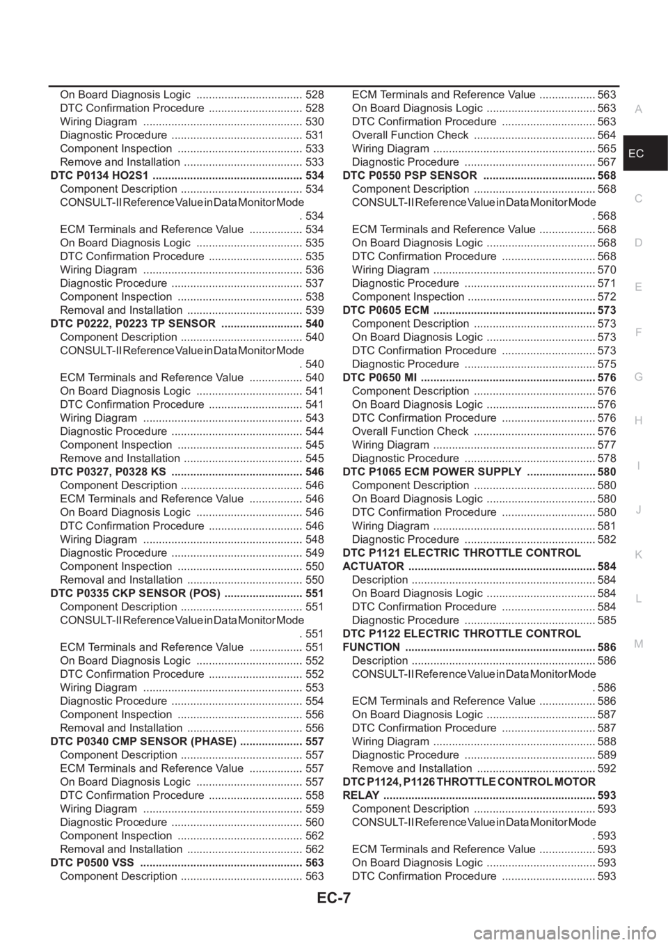
EC-7
C
D
E
F
G
H
I
J
K
L
M
ECA On Board Diagnosis Logic ................................... 528
DTC Confirmation Procedure ............................... 528
Wiring Diagram .................................................... 530
Diagnostic Procedure ........................................... 531
Component Inspection ......................................... 533
Remove and Installation ....................................... 533
DTC P0134 HO2S1 ................................................. 534
Component Description ........................................ 534
CONSULT-II Reference Value in Data Monitor Mode
. 534
ECM Terminals and Reference Value .................. 534
On Board Diagnosis Logic ................................... 535
DTC Confirmation Procedure ............................... 535
Wiring Diagram .................................................... 536
Diagnostic Procedure ........................................... 537
Component Inspection ......................................... 538
Removal and Installation ...................................... 539
DTC P0222, P0223 TP SENSOR ........................... 540
Component Description ........................................ 540
CONSULT-II Reference Value in Data Monitor Mode
. 540
ECM Terminals and Reference Value .................. 540
On Board Diagnosis Logic ................................... 541
DTC Confirmation Procedure ............................... 541
Wiring Diagram .................................................... 543
Diagnostic Procedure ........................................... 544
Component Inspection ......................................... 545
Remove and Installation ....................................... 545
DTC P0327, P0328 KS ........................................... 546
Component Description ........................................ 546
ECM Terminals and Reference Value .................. 546
On Board Diagnosis Logic ................................... 546
DTC Confirmation Procedure ............................... 546
Wiring Diagram .................................................... 548
Diagnostic Procedure ........................................... 549
Component Inspection ......................................... 550
Removal and Installation ...................................... 550
DTC P0335 CKP SENSOR (POS) .......................... 551
Component Description ........................................ 551
CONSULT-II Reference Value in Data Monitor Mode
. 551
ECM Terminals and Reference Value .................. 551
On Board Diagnosis Logic ................................... 552
DTC Confirmation Procedure ............................... 552
Wiring Diagram .................................................... 553
Diagnostic Procedure ........................................... 554
Component Inspection ......................................... 556
Removal and Installation ...................................... 556
DTC P0340 CMP SENSOR (PHASE) ..................... 557
Component Description .......................................
. 557
ECM Terminals and Reference Value .................. 557
On Board Diagnosis Logic ................................... 557
DTC Confirmation Procedure ............................... 558
Wiring Diagram .................................................... 559
Diagnostic Procedure ........................................... 560
Component Inspection ......................................... 562
Removal and Installation ...................................... 562
DTC P0500 VSS ..................................................... 563
Component Description ........................................ 563ECM Terminals and Reference Value ...................563
On Board Diagnosis Logic ....................................563
DTC Confirmation Procedure ...............................563
Overall Function Check ........................................564
Wiring Diagram .....................................................565
Diagnostic Procedure ...........................................567
DTC P0550 PSP SENSOR .....................................568
Component Description ........................................568
CONSULT-II Reference Value in Data Monitor Mode
.568
ECM Terminals and Reference Value ...................568
On Board Diagnosis Logic ....................................568
DTC Confirmation Procedure ...............................568
Wiring Diagram .....................................................570
Diagnostic Procedure ...........................................571
Component Inspection ..........................................572
DTC P0605 ECM .....................................................573
Component Description ........................................573
On Board Diagnosis Logic ....................................573
DTC Confirmation Procedure ...............................573
Diagnostic Procedure ...........................................575
DTC P0650 MI .........................................................576
Component Description ........................................576
On Board Diagnosis Logic ....................................576
DTC Confirmation Procedure ...............................576
Overall Function Check ........................................576
Wiring Diagram .....................................................577
Diagnostic Procedure ...........................................578
DTC P1065 ECM POWER SUPPLY .......................580
Component Description ........................................580
On Board Diagnosis Logic ....................................580
DTC Confirmation Procedure ...............................580
Wiring Diagram .....................................................581
Diagnostic Procedure ...........................................582
DTC P1121 ELECTRIC THROTTLE CONTROL
ACTUATOR .............................................................584
Description ............................................................584
On Board Diagnosis Logic ....................................584
DTC Confirmation Procedure ...............................584
Diagnostic Procedure ...........................................585
DTC P1122 ELECTRIC THROTTLE CONTROL
FUNCTION ..............................................................586
Description ............................................................586
CONSULT-II Reference Value in Data Monitor Mode
.586
ECM Terminals and Reference Value ...................586
On Board Diagnosis Logic ....................................587
DTC Confirmation Procedure ...............................587
Wiring Diagram .....................................................588
Diagnostic Procedure ...........................................589
Remove and Installation .......................................592
DTC P1124, P1126 THROTTLE CONTROL MOTOR
RELAY .....................................................................593
Component Description ........................................593
CONSULT-II Reference Value in Data Monitor Mode
.593
ECM Terminals and Reference Value ...................593
On Board Diagnosis Logic ....................................593
DTC Confirmation Procedure ...............................593
Page 358 of 3833
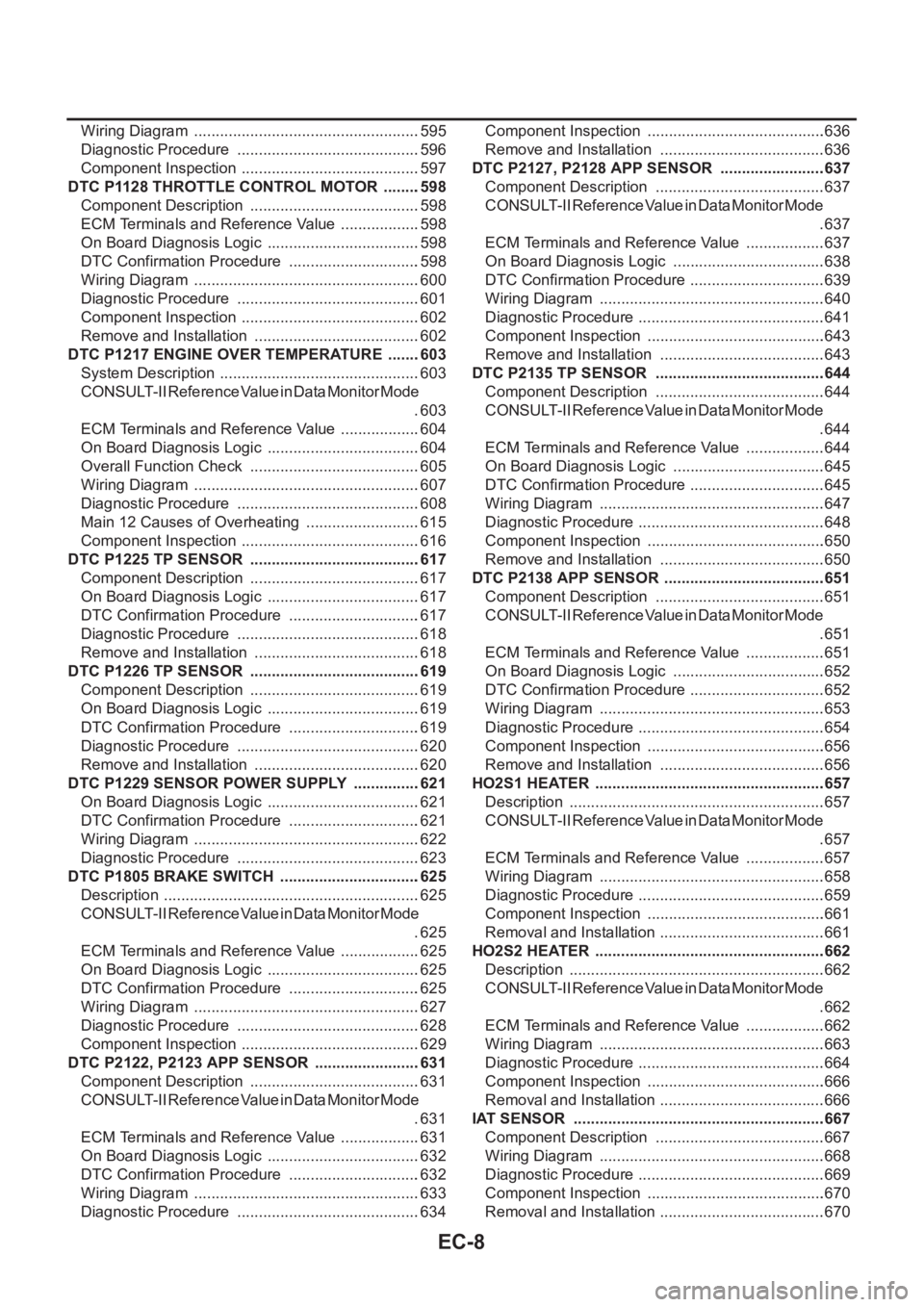
EC-8
Wiring Diagram .....................................................595
Diagnostic Procedure ...........................................596
Component Inspection ..........................................597
DTC P1128 THROTTLE CONTROL MOTOR .........598
Component Description ........................................598
ECM Terminals and Reference Value ...................598
On Board Diagnosis Logic ....................................598
DTC Confirmation Procedure ...............................598
Wiring Diagram .....................................................600
Diagnostic Procedure ...........................................601
Component Inspection ..........................................602
Remove and Installation .......................................602
DTC P1217 ENGINE OVER TEMPERATURE ........603
System Description ...............................................603
CONSULT-II Reference Value in Data Monitor Mode
.603
ECM Terminals and Reference Value ...................604
On Board Diagnosis Logic ....................................604
Overall Function Check ........................................605
Wiring Diagram .....................................................607
Diagnostic Procedure ...........................................608
Main 12 Causes of Overheating ...........................615
Component Inspection ..........................................616
DTC P1225 TP SENSOR ........................................617
Component Description ........................................617
On Board Diagnosis Logic ....................................617
DTC Confirmation Procedure ...............................617
Diagnostic Procedure ...........................................618
Remove and Installation .......................................618
DTC P1226 TP SENSOR ........................................619
Component Description ........................................619
On Board Diagnosis Logic ....................................619
DTC Confirmation Procedure ...............................619
Diagnostic Procedure ...........................................620
Remove and Installation .......................................620
DTC P1229 SENSOR POWER SUPPLY ................621
On Board Diagnosis Logic ....................................621
DTC Confirmation Procedure ...............................621
Wiring Diagram .....................................................622
Diagnostic Procedure ...........................................623
DTC P1805 BRAKE SWITCH .................................625
Description ............................................................625
CONSULT-II Reference Value in Data Monitor Mode
.625
ECM Terminals and Reference Value ...................625
On Board Diagnosis Logic ....................................625
DTC Confirmation Procedure ...............................625
Wiring Diagram .....................................................627
Diagnostic Procedure ...........................................628
Component Inspection ..........................................629
DTC P2122, P2123 APP SENSOR .........................631
Component Description ........................................631
CONSULT-II Reference Value in Data Monitor Mode
.631
ECM Terminals and Reference Value ...................631
On Board Diagnosis Logic ....................................632
DTC Confirmation Procedure ...............................632
Wiring Diagram .....................................................633
Diagnostic Procedure ...........................................634Component Inspection ..........................................636
Remove and Installation .......................................636
DTC P2127, P2128 APP SENSOR .........................637
Component Description ........................................637
CONSULT-II Reference Value in Data Monitor Mode
.637
ECM Terminals and Reference Value ...................637
On Board Diagnosis Logic ....................................638
DTC Confirmation Procedure ................................639
Wiring Diagram .....................................................640
Diagnostic Procedure ............................................641
Component Inspection ..........................................643
Remove and Installation .......................................643
DTC P2135 TP SENSOR ........................................644
Component Description ........................................644
CONSULT-II Reference Value in Data Monitor Mode
.644
ECM Terminals and Reference Value ...................644
On Board Diagnosis Logic ....................................645
DTC Confirmation Procedure ................................645
Wiring Diagram .....................................................647
Diagnostic Procedure ............................................648
Component Inspection ..........................................650
Remove and Installation .......................................650
DTC P2138 APP SENSOR ......................................651
Component Description ........................................651
CONSULT-II Reference Value in Data Monitor Mode
.651
ECM Terminals and Reference Value ...................651
On Board Diagnosis Logic ....................................652
DTC Confirmation Procedure ................................652
Wiring Diagram .....................................................653
Diagnostic Procedure ............................................654
Component Inspection ..........................................656
Remove and Installation .......................................656
HO2S1 HEATER ......................................................657
Description ............................................................657
CONSULT-II Reference Value in Data Monitor Mode
.657
ECM Terminals and Reference Value ...................657
Wiring Diagram ....................................................
.658
Diagnostic Procedure ............................................659
Component Inspection ..........................................661
Removal and Installation .......................................661
HO2S2 HEATER ......................................................662
Description ............................................................662
CONSULT-II Reference Value in Data Monitor Mode
.662
ECM Terminals and Reference Value ...................662
Wiring Diagram .....................................................663
Diagnostic Procedure ............................................664
Component Inspection ..........................................666
Removal and Installation .......................................666
IAT SENSOR ...........................................................667
Component Description ........................................667
Wiring Diagram .....................................................668
Diagnostic Procedure ............................................669
Component Inspection ..........................................670
Removal and Installation .......................................670
Page 359 of 3833

EC-9
C
D
E
F
G
H
I
J
K
L
M
ECA HO2S1 .................................................................... 671
Component Description ........................................ 671
CONSULT-II Reference Value in Data Monitor Mode
. 671
ECM Terminals and Reference Value .................. 671
Wiring Diagram .................................................... 672
Diagnostic Procedure ........................................... 673
Component Inspection ......................................... 674
Removal and Installation ...................................... 676
HO2S2 .................................................................... 677
Component Description ........................................ 677
CONSULT-II Reference Value in Data Monitor Mode
. 677
ECM Terminals and Reference Value .................. 677
Wiring Diagram .................................................... 678
Diagnostic Procedure ........................................... 679
Component Inspection ......................................... 680
Removal and Installation ...................................... 682
IGNITION SIGNAL .................................................. 683
Component Description ........................................ 683
ECM Terminals and Reference Value .................. 683
Wiring Diagram .................................................... 684
Diagnostic Procedure ........................................... 686
Component Inspection ......................................... 690
Removal and Installation ...................................... 691
EVAP CANISTER PURGE VOLUME CONTROL
SOLENOID VALVE ................................................. 692
Description ........................................................... 692
CONSULT-II Reference Value in Data Monitor Mode
. 692
ECM Terminals and Reference Value .................. 692
Wiring Diagram .................................................... 694
Diagnostic Procedure ........................................... 695
Component Inspection ......................................... 698
Removal and Installation ...................................... 698
IVT CONTROL SOLENOID VALVE ........................ 699
Description ........................................................... 699
CONSULT-II Reference Value in Data Monitor Mode
. 699
ECM Terminals and Reference Value .................. 700
Wiring Diagram .................................................... 701
Diagnostic Procedure ........................................... 702
Component Inspection ......................................... 704
Removal and Installation ...................................... 704
PNP SWITCH .......................................................... 705
Component Description ........................................ 705
CONSULT-II Reference Value in Data Monitor Mode
. 705
ECM Terminals and Reference Value .................. 705
Wiring Diagram ...................................................
. 706
Diagnostic Procedure ........................................... 707
INJECTOR CIRCUIT ............................................... 709
Component Description ........................................ 709
CONSULT-II Reference Value in Data Monitor Mode
. 709
ECM Terminals and Reference Value .................. 709
Wiring Diagram .................................................... 710
Diagnostic Procedure ............................................ 711Component Inspection ..........................................713
Removal and Installation ......................................713
VIAS ........................................................................714
Description ............................................................714
CONSULT-II Reference Value in Data Monitor Mode
.715
ECM Terminals and Reference Value ...................715
Wiring Diagram .....................................................716
Diagnostic Procedure ...........................................717
Component Inspection ..........................................720
Removal and Installation ......................................721
START SIGNAL ......................................................722
CONSULT-II Reference Value in Data Monitor Mode
.722
ECM Terminals and Reference Value ...................722
Wiring Diagram .....................................................723
Diagnostic Procedure ...........................................724
FUEL PUMP CIRCUIT ............................................726
Description ............................................................726
CONSULT-II Reference Value in Data Monitor Mode
.726
ECM Terminals and Reference Value ...................726
Wiring Diagram .....................................................728
Diagnostic Procedure ...........................................729
Component Inspection ..........................................731
Removal and Installation ......................................732
REFRIGERANT PRESSURE SENSOR ..................733
Component Description ........................................733
ECM Terminals and Reference Value ...................733
Wiring Diagram .....................................................734
Diagnostic Procedure ...........................................735
Removal and Installation ......................................736
ELECTRICAL LOAD SIGNAL ................................737
CONSULT-II Reference Value in Data Monitor Mode
.737
ECM Terminals and Reference Value ...................737
Wiring Diagram .....................................................738
Diagnostic Procedure ...........................................740
DATA LINK CONNECTOR ......................................745
Wiring Diagram .....................................................745
EVAPORATIVE EMISSION SYSTEM .....................746
Description ...................................................
.........746
Component Inspection ..........................................748
POSITIVE CRANKCASE VENTILATION ...............749
Description ............................................................749
Component Inspection ..........................................749
SERVICE DATA AND SPECIFICATIONS (SDS) ....751
Fuel Pressure .......................................................751
Idle Speed and Ignition Timing .............................751
Calculated Load Value ..........................................751
Mass Air Flow Sensor ...........................................751
Intake Air Temperature Sensor .............................751
Engine Coolant Temperature Sensor ...................751
Heated Oxygen Sensor 1 Heater .........................751
Heated Oxygen sensor 2 Heater ..........................751
Crankshaft Position Sensor (POS) .......................751
Camshaft Position Sensor (PHASE) ....................752
Throttle Control Motor ...........................................752
Page 360 of 3833
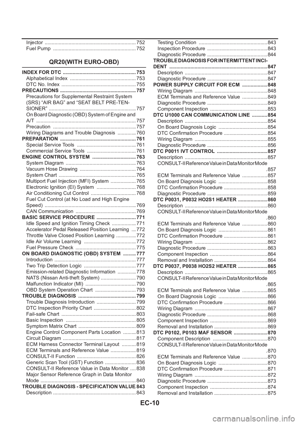
EC-10
Injector ..................................................................752
Fuel Pump ............................................................752
QR20(WITH EURO-OBD)
INDEX FOR DTC .....................................................753
Alphabetical Index ................................................753
DTC No. Index ......................................................755
PRECAUTIONS .......................................................757
Precautions for Supplemental Restraint System
(SRS) “AIR BAG” and “SEAT BELT PRE-TEN-
SIONER” ...............................................................757
On Board Diagnostic (OBD) System of Engine and
A/T ........................................................................757
Precaution ............................................................757
Wiring Diagrams and Trouble Diagnosis ..............760
PREPARATION .......................................................761
Special Service Tools ...........................................761
Commercial Service Tools ....................................761
ENGINE CONTROL SYSTEM ................................763
System Diagram ...................................................763
Vacuum Hose Drawing .........................................764
System Chart ........................................................765
Multiport Fuel Injection (MFI) System ...................765
Electronic Ignition (EI) System .............................768
Air Conditioning Cut Control .................................768
Fuel Cut Control (at No Load and High Engine
Speed) ..................................................................769
CAN Communication ............................................769
BASIC SERVICE PROCEDURE .............................771
Idle Speed and Ignition Timing Check ..................771
Accelerator Pedal Released Position Learning ....772
Throttle Valve Closed Position Learning ...............772
Idle Air Volume Learning ......................................772
Fuel Pressure Check ............................................775
ON BOARD DIAGNOSTIC (OBD) SYSTEM ..........777
Introduction ...........................................................777
Two Trip Detection Logic ......................................777
Emission-related Diagnostic Information ..............778
NATS (Nissan Anti-theft System) ..........................790
Malfunction Indicator (MI) .....................................790
OBD System Operation Chart ..............................793
TROUBLE DIAGNOSIS ..........................................799
Trouble Diagnosis Introduction .............................799
DTC Inspection Priority Chart ...............................802
Fail-safe Chart ......................................................803
Basic Inspection ...................................................805
Symptom Matrix Chart ..........................................809
Engine Control Component Parts Location ..........813
Circuit Diagram .....................................................817
ECM Harness Connector Terminal Layout ...........819
ECM Terminals and Reference Value ...................819
CONSULT-II Function ...........................................826
Generic Scan Tool (GST) Function .......................836
CONSULT-II Reference Value in Data Monitor .....838
Major Sensor Reference Graph in Data Monitor
Mode .....................................................................840
TROUBLE DIAGNOSIS - SPECIFICATION VALUE .843
Description ............................................................843Testing Condition ..................................................843
Inspection Procedure ........................................... .843
Diagnostic Procedure ............................................844
TROUBLE DIAGNOSIS FOR INTERMITTENT INCI-
DENT .......................................................................847
Description ............................................................847
Diagnostic Procedure ............................................847
POWER SUPPLY CIRCUIT FOR ECM ...................848
Wiring Diagram .....................................................848
ECM Terminals and Reference Value ...................849
Diagnostic Procedure ............................................849
Component Inspection ..........................................853
DTC U1000 CAN COMMUNICATION LINE ............854
Description ............................................................854
On Board Diagnosis Logic ....................................854
DTC Confirmation Procedure ................................854
Wiring Diagram .....................................................855
Diagnostic Procedure ............................................856
DTC P0011 IVT CONTROL .....................................857
Description ............................................................857
CONSULT-II Reference Value in Data Monitor Mode
.857
ECM Terminals and Reference Value ...................857
On Board Diagnosis Logic ....................................858
DTC Confirmation Procedure ................................858
Diagnostic Procedure ............................................859
DTC P0031, P0032 HO2S1 HEATER ......................860
Description ............................................................860
CONSULT-II Reference Value in Data Monitor Mode
.860
ECM Terminals and Reference Value ...................860
On Board Diagnosis Logic ....................................861
DTC Confirmation Procedure ................................861
Wiring Diagram .....................................................862
Diagnostic Procedure ............................................863
Component Inspection ..........................................864
Removal and Installation .......................................864
DTC P0037, P0038 HO2S2 HEATER .....................
.865
Description ............................................................865
CONSULT-II Reference Value in Data Monitor Mode
.865
ECM Terminals and Reference Value ...................865
On Board Diagnosis Logic ....................................866
DTC Confirmation Procedure ................................866
Wiring Diagram .....................................................867
Diagnostic Procedure ............................................868
Component Inspection ..........................................869
Removal and Installation .......................................869
DTC P0102, P0103 MAF SENSOR .........................870
Component Description ........................................870
CONSULT-II Reference Value in Data Monitor Mode
.870
ECM Terminals and Reference Value ...................870
On Board Diagnosis Logic ....................................870
DTC Confirmation Procedure ................................871
Wiring Diagram .....................................................872
Diagnostic Procedure ............................................873
Component Inspection ..........................................874
Removal and Installation .......................................875
Page 361 of 3833
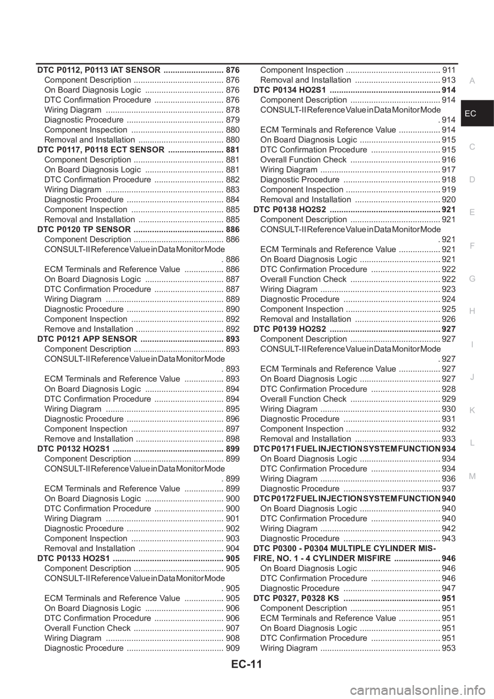
EC-11
C
D
E
F
G
H
I
J
K
L
M
ECA DTC P0112, P0113 IAT SENSOR ........................... 876
Component Description ........................................ 876
On Board Diagnosis Logic ................................... 876
DTC Confirmation Procedure ............................... 876
Wiring Diagram .................................................... 878
Diagnostic Procedure ........................................... 879
Component Inspection ......................................... 880
Removal and Installation ...................................... 880
DTC P0117, P0118 ECT SENSOR ......................... 881
Component Description ........................................ 881
On Board Diagnosis Logic ................................... 881
DTC Confirmation Procedure ............................... 882
Wiring Diagram .................................................... 883
Diagnostic Procedure ........................................... 884
Component Inspection ......................................... 885
Removal and Installation ...................................... 885
DTC P0120 TP SENSOR ........................................ 886
Component Description ........................................ 886
CONSULT-II Reference Value in Data Monitor Mode
. 886
ECM Terminals and Reference Value .................. 886
On Board Diagnosis Logic ................................... 887
DTC Confirmation Procedure ............................... 887
Wiring Diagram .................................................... 889
Diagnostic Procedure ........................................... 890
Component Inspection ......................................... 892
Remove and Installation ....................................... 892
DTC P0121 APP SENSOR ..................................... 893
Component Description ........................................ 893
CONSULT-II Reference Value in Data Monitor Mode
. 893
ECM Terminals and Reference Value .................. 893
On Board Diagnosis Logic ................................... 894
DTC Confirmation Procedure ............................... 894
Wiring Diagram .................................................... 895
Diagnostic Procedure ........................................... 896
Component Inspection ......................................... 897
Remove and Installation ....................................... 898
DTC P0132 HO2S1 ................................................. 899
Component Description ........................................ 899
CONSULT-II Reference Value in Data Monitor Mode
. 899
ECM Terminals and Reference Value .................. 899
On Board Diagnosis Logic ................................... 900
DTC Confirmation Procedure ............................... 900
Wiring Diagram .................................................... 901
Diagnostic Procedure ........................................... 902
Component Inspection ......................................... 903
Removal and Installation ...................................... 904
DTC P0133 HO2S1 ...............................................
.. 905
Component Description ........................................ 905
CONSULT-II Reference Value in Data Monitor Mode
. 905
ECM Terminals and Reference Value .................. 905
On Board Diagnosis Logic ................................... 906
DTC Confirmation Procedure ............................... 906
Overall Function Check ........................................ 907
Wiring Diagram .................................................... 908
Diagnostic Procedure ........................................... 909Component Inspection ..........................................911
Removal and Installation ......................................913
DTC P0134 HO2S1 ................................................ .914
Component Description ........................................914
CONSULT-II Reference Value in Data Monitor Mode
.914
ECM Terminals and Reference Value ...................914
On Board Diagnosis Logic ....................................915
DTC Confirmation Procedure ...............................915
Overall Function Check ........................................916
Wiring Diagram .....................................................917
Diagnostic Procedure ...........................................918
Component Inspection ..........................................919
Removal and Installation ......................................920
DTC P0138 HO2S2 ................................................ .921
Component Description ........................................921
CONSULT-II Reference Value in Data Monitor Mode
.921
ECM Terminals and Reference Value ...................921
On Board Diagnosis Logic ....................................921
DTC Confirmation Procedure ...............................922
Overall Function Check ........................................922
Wiring Diagram .....................................................923
Diagnostic Procedure ...........................................924
Component Inspection ..........................................925
Removal and Installation ......................................926
DTC P0139 HO2S2 ................................................ .927
Component Description ........................................927
CONSULT-II Reference Value in Data Monitor Mode
.927
ECM Terminals and Reference Value ...................927
On Board Diagnosis Logic ....................................927
DTC Confirmation Procedure ...............................928
Overall Function Check ........................................929
Wiring Diagram .....................................................930
Diagnostic Procedure ...........................................931
Component Inspection ..........................................932
Removal and Installation ......................................933
DTC P0171 FUEL INJECTION SYSTEM FUNCTION .934
On Board Diagnosis Logic ....................................934
DTC Confirmation Procedure ...............................934
Wiring Diagram .....................................................936
Diagnostic Procedure ...........................................937
DTC P0172 FUEL INJECTION SYSTEM FUNCTION .940
On Board Diagnosis Logic ....................................940
DTC Confirmation Procedure ...............................940
Wiring Diagram .....................................................942
Diagnostic Procedure ...........................................943
DTC P0300 - P0304 MULTIPLE CYLINDER MIS-
FIRE, NO. 1 - 4 CYLINDER MISFIRE .....................946
On Board Diagnosis Logic ....................................946
DTC Confirmation Procedure ...............................946
Diagnostic Procedure ...........................................947
DTC P0327, P0328 KS ...........................................951
Component Description ........................................951
ECM Terminals and Reference Value ...................951
On Board Diagnosis Logic ....................................951
DTC Confirmation Procedure ...............................951
Wiring Diagram .....................................................953
Page 362 of 3833
EC-12
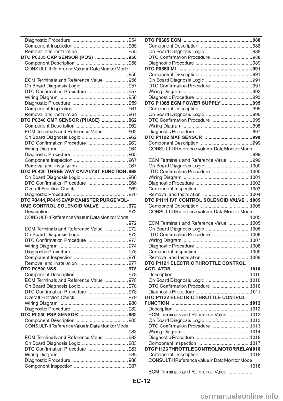
Diagnostic Procedure ...........................................954
Component Inspection ..........................................955
Removal and Installation ......................................955
DTC P0335 CKP SENSOR (POS) ..........................956
Component Description ........................................956
CONSULT-II Reference Value in Data Monitor Mode
.956
ECM Terminals and Reference Value ...................956
On Board Diagnosis Logic ....................................957
DTC Confirmation Procedure ...............................957
Wiring Diagram .....................................................958
Diagnostic Procedure ...........................................959
Component Inspection ..........................................961
Removal and Installation ......................................961
DTC P0340 CMP SENSOR (PHASE) .....................962
Component Description ........................................962
ECM Terminals and Reference Value ...................962
On Board Diagnosis Logic ....................................962
DTC Confirmation Procedure ...............................963
Wiring Diagram .....................................................964
Diagnostic Procedure ...........................................965
Component Inspection ..........................................967
Removal and Installation ......................................967
DTC P0420 THREE WAY CATALYST FUNCTION . 968
On Board Diagnosis Logic ....................................968
DTC Confirmation Procedure ...............................968
Overall Function Check ........................................969
Diagnostic Procedure ...........................................970
DTC P0444, P0445 EVAP CANISTER PURGE VOL-
UME CONTROL SOLENOID VALVE ......................972
Description ............................................................972
CONSULT-II Reference Value in Data Monitor Mode
.972
ECM Terminals and Reference Value ...................972
On Board Diagnosis Logic ....................................973
DTC Confirmation Procedure ...............................973
Wiring Diagram .....................................................974
Diagnostic Procedure ...........................................975
Component Inspection ..........................................976
Removal and Installation ......................................977
DTC P0500 VSS ......................................................978
Component Description ........................................978
ECM Terminals and Reference Value ...................978
On Board Diagnosis Logic ....................................978
DTC Confirmation Procedure ...............................978
Overall Function Check ........................................979
Wiring Diagram .....................................................980
Diagnostic Procedure ...........................................982
DTC P0550 PSP SENSOR ......................................983
Component Description ........................................983
CONSULT-II Reference Value in Data Monitor Mode
.983
ECM Terminals and Reference Value ...................983
On Board Diagnosis Logic ....................................983
DTC Confirmation Procedure ...............................983
Wiring Diagram .....................................................985
Diagnostic Procedure ...........................................986
Component Inspection ..........................................987DTC P0605 ECM .....................................................988
Component Description ........................................988
On Board Diagnosis Logic ....................................988
DTC Confirmation Procedure ................................988
Diagnostic Procedure ............................................989
DTC P0650 MI .........................................................991
Component Description ........................................991
On Board Diagnosis Logic ....................................991
DTC Confirmation Procedure ................................991
Wiring Diagram .....................................................992
Diagnostic Procedure ............................................993
DTC P1065 ECM POWER SUPPLY ........................995
Component Description ........................................995
On Board Diagnosis Logic ....................................995
DTC Confirmation Procedure ................................995
Wiring Diagram .....................................................996
Diagnostic Procedure ............................................997
DTC P1102 MAF SENSOR .....................................999
Component Description ........................................999
CONSULT-II Reference Value in Data Monitor Mode
.999
ECM Terminals and Reference Value ...................999
On Board Diagnosis Logic ...................................1000
DTC Confirmation Procedure ...............................1000
Wiring Diagram ....................................................1001
Diagnostic Procedure ........................................... 1002
Component Inspection .........................................1003
Removal and Installation ......................................1004
DTC P1111 IVT CONTROL SOLENOID VALVE ....1005
Component Description .......................................1005
CONSULT-II Reference Value in Data Monitor Mode
1005
ECM Terminals and Reference Value ..................1005
On Board Diagnosis Logic ...................................1005
DTC Confirmation Procedure ...............................1006
Wiring Diagram ....................................................1007
Diagnostic Procedure ........................................... 1008
Component Inspection .........................................1009
Removal and Installation ......................................1009
DTC P1121 ELECTRIC THROTTLE CONTROL
ACTUATOR ............................................................1010
Description ...........................................................1010
On Board Diagnosis Logic ...................................1010
DTC Confirmation Procedure ...............................1010
Diagnostic Procedure ........................................... 1011
DTC P1122 ELECTRIC THROTTLE CONTROL
FUNCTION .............................................................1012
Description ...........................................................1012
ECM Terminals and Reference Value ..................1012
On Board Diagnosis Logic ...................................1012
DTC Confirmation Procedure ...............................1013
Wiring Diagram ....................................................1014
Diagnostic Procedure ........................................... 1015
Component Inspection .........................................1017
DTC P1123 THROTTLE CONTROL MOTOR RELAY 1018
Component Description .......................................1018
CONSULT-II Reference Value in Data Monitor Mode
1018
ECM Terminals and Reference Value ..................
Page 363 of 3833
EC-13
C
D
E
F
G
H
I
J
K
L
M
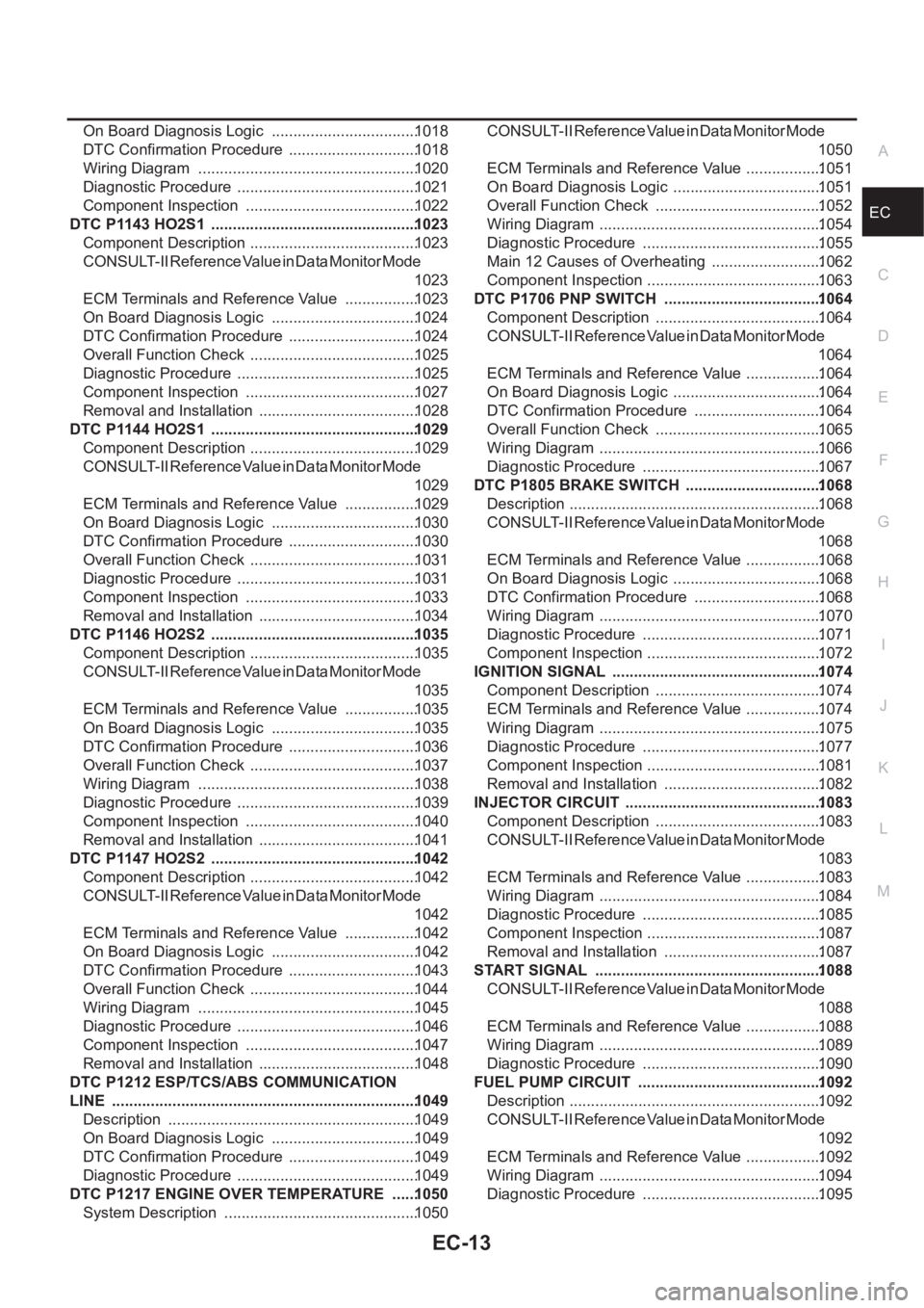
ECA On Board Diagnosis Logic ..................................1018
DTC Confirmation Procedure ..............................1018
Wiring Diagram ...................................................1020
Diagnostic Procedure ..........................................1021
Component Inspection ........................................1022
DTC P1143 HO2S1 ................................................1023
Component Description .......................................1023
CONSULT-II Reference Value in Data Monitor Mode
1023
ECM Terminals and Reference Value .................1023
On Board Diagnosis Logic ..................................1024
DTC Confirmation Procedure ..............................1024
Overall Function Check .......................................1025
Diagnostic Procedure ..........................................1025
Component Inspection ........................................1027
Removal and Installation .....................................1028
DTC P1144 HO2S1 ................................................1029
Component Description .......................................1029
CONSULT-II Reference Value in Data Monitor Mode
1029
ECM Terminals and Reference Value .................1029
On Board Diagnosis Logic ..................................1030
DTC Confirmation Procedure ..............................1030
Overall Function Check .......................................1031
Diagnostic Procedure ..........................................1031
Component Inspection ........................................1033
Removal and Installation .....................................1034
DTC P1146 HO2S2 ................................................1035
Component Description .......................................1035
CONSULT-II Reference Value in Data Monitor Mode
1035
ECM Terminals and Reference Value .................1035
On Board Diagnosis Logic ..................................1035
DTC Confirmation Procedure ..............................1036
Overall Function Check .......................................1037
Wiring Diagram ...................................................1038
Diagnostic Procedure ..........................................1039
Component Inspection ........................................1040
Removal and Installation .....................................1041
DTC P1147 HO2S2 ................................................1042
Component Description .......................................1042
CONSULT-II Reference Value in Data Monitor Mode
1042
ECM Terminals and Reference Value .................1042
On Board Diagnosis Logic ..................................1042
DTC Confirmation Procedure ..............................1043
Overall Function Check .......................................1044
Wiring Diagram ...................................................1045
Diagnostic Procedure ..........................................1046
Component Inspection ........................................1047
Removal and Installation .....................................1048
DTC P1212 ESP/TCS/ABS COMMUNICATION
LINE .......................................................................1049
Description ..........................................................1049
On Board Diagnosis Logic ..................................1049
DTC Confirmation Procedure ..............................1049
Diagnostic Procedure ..........................................1049
DTC P1217 ENGINE OVER TEMPERATURE ......1050
System Description .............................................1050CONSULT-II Reference Value in Data Monitor Mode
1050
ECM Terminals and Reference Value ..................1051
On Board Diagnosis Logic ...................................1051
Overall Function Check .......................................1052
Wiring Diagram ....................................................1054
Diagnostic Procedure ..........................................1055
Main 12 Causes of Overheating ..........................1062
Component Inspection .........................................1063
DTC P1706 PNP SWITCH .....................................1064
Component Description .......................................1064
CONSULT-II Reference Value in Data Monitor Mode
1064
ECM Terminals and Reference Value ..................1064
On Board Diagnosis Logic ...................................1064
DTC Confirmation Procedure ..............................1064
Overall Function Check .......................................1065
Wiring Diagram ....................................................1066
Diagnostic Procedure ..........................................1067
DTC P1805 BRAKE SWITCH ................................1068
Description ...........................................................1068
CONSULT-II Reference Value in Data Monitor Mode
1068
ECM Terminals and Reference Value ..................1068
On Board Diagnosis Logic ...................................1068
DTC Confirmation Procedure ..............................1068
Wiring Diagram ....................................................1070
Diagnostic Procedure ..........................................1071
Component Inspection .........................................1072
IGNITION SIGNAL .................................................1074
Component Description .......................................1074
ECM Terminals and Reference Value ..................1074
Wiring Diagram ....................................................1075
Diagnostic Procedure ..........................................1077
Component Inspection .........................................1081
Removal and Installation .....................................1082
INJECTOR CIRCUIT ..............................................1083
Component Description .......................................1083
CONSULT-II Reference Value in Data Monitor Mode
1083
ECM Terminals and Reference Value ..................1083
Wiring Diagram ....................................................
1084
Diagnostic Procedure ..........................................1085
Component Inspection .........................................1087
Removal and Installation .....................................1087
START SIGNAL .....................................................1088
CONSULT-II Reference Value in Data Monitor Mode
1088
ECM Terminals and Reference Value ..................1088
Wiring Diagram ....................................................1089
Diagnostic Procedure ..........................................1090
FUEL PUMP CIRCUIT ...........................................1092
Description ...........................................................1092
CONSULT-II Reference Value in Data Monitor Mode
1092
ECM Terminals and Reference Value ..................1092
Wiring Diagram ....................................................1094
Diagnostic Procedure ..........................................1095