2001 NISSAN X-TRAIL diagram
[x] Cancel search: diagramPage 23 of 3833
HOW TO USE THIS MANUAL
GI-21
C
D
E
F
G
H
I
J
K
L
MB
GI
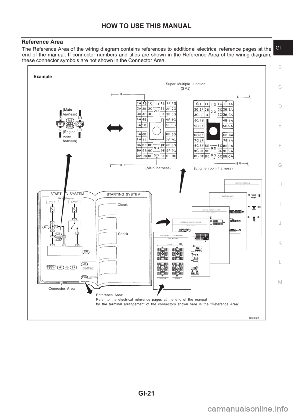
Reference Area
The Reference Area of the wiring diagram contains references to additional electrical reference pages at the
end of the manual. If connector numbers and titles are shown in the Reference Area of the wiring diagram,
these connector symbols are not shown in the Connector Area.
SGI092A
Page 26 of 3833
GI-24
SERVICE INFORMATION FOR ELECTRICAL INCIDENT
●Heat sensitive
●Freezing
●Water intrusion
●Electrical load
●Cold or hot start up
Get a thorough description of the incident from the customer. It is important for simulating the conditions of the
problem.
Vehicle Vibration
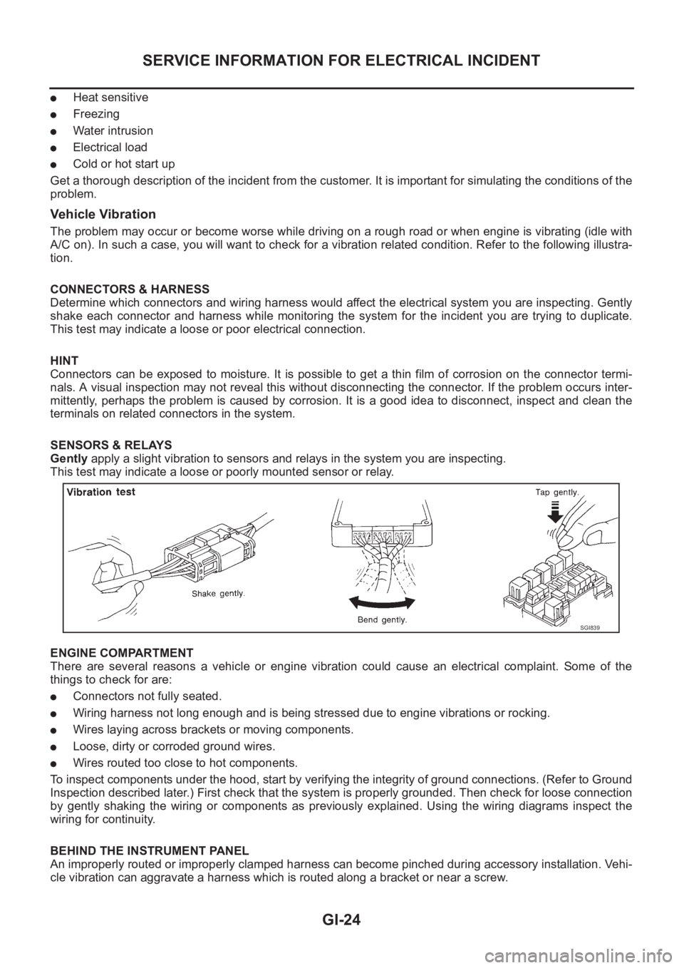
The problem may occur or become worse while driving on a rough road or when engine is vibrating (idle with
A/C on). In such a case, you will want to check for a vibration related condition. Refer to the following illustra-
tion.
CONNECTORS & HARNESS
Determine which connectors and wiring harness would affect the electrical system you are inspecting. Gently
shake each connector and harness while monitoring the system for the incident you are trying to duplicate.
This test may indicate a loose or poor electrical connection.
HINT
Connectors can be exposed to moisture. It is possible to get a thin film of corrosion on the connector termi-
nals. A visual inspection may not reveal this without disconnecting the connector. If the problem occurs inter-
mittently, perhaps the problem is caused by corrosion. It is a good idea to disconnect, inspect and clean the
terminals on related connectors in the system.
SENSORS & RELAYS
Gently apply a slight vibration to sensors and relays in the system you are inspecting.
This test may indicate a loose or poorly mounted sensor or relay.
ENGINE COMPARTMENT
There are several reasons a vehicle or engine vibration could cause an electrical complaint. Some of the
things to check for are:
●Connectors not fully seated.
●Wiring harness not long enough and is being stressed due to engine vibrations or rocking.
●Wires laying across brackets or moving components.
●Loose, dirty or corroded ground wires.
●Wires routed too close to hot components.
To inspect components under the hood, start by verifying the integrity of ground connections. (Refer to Ground
Inspection described later.) First check that the system is properly grounded. Then check for loose connection
by gently shaking the wiring or components as previously explained. Using the wiring diagrams inspect the
wiring for continuity.
BEHIND THE INSTRUMENT PANEL
An improperly routed or improperly clamped harness can become pinched during accessory installation. Vehi-
cle vibration can aggravate a harness which is routed along a bracket or near a screw.
SGI839
Page 36 of 3833
GI-34
CONSULT-II CHECKING SYSTEM
Checking Equipment
EAS000GB
When ordering the following equipment, contact your NISSAN/INFINITI distributor.
NOTE:
●The CONSULT-II must be used in conjunction with a program card.
CONSULT-II does not require loading (Initialization) procedure.
●Be sure the CONSULT-II is turned off before installing or removing a program card.
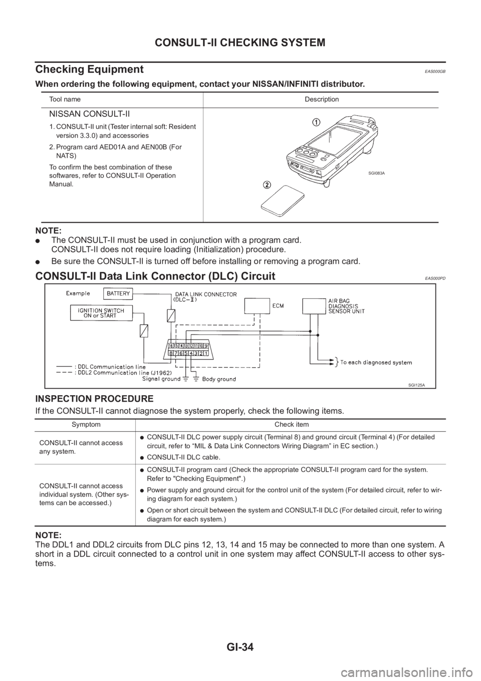
CONSULT-II Data Link Connector (DLC) CircuitEAS000PD
INSPECTION PROCEDURE
If the CONSULT-II cannot diagnose the system properly, check the following items.
NOTE:
The DDL1 and DDL2 circuits from DLC pins 12, 13, 14 and 15 may be connected to more than one system. A
short in a DDL circuit connected to a control unit in one system may affect CONSULT-II access to other sys-
tems.
To o l n a m eDescription
NISSAN CONSULT-II
1. CONSULT-II unit (Tester internal soft: Resident
version 3.3.0) and accessories
2. Program card AED01A and AEN00B (For
NATS)
To confirm the best combination of these
softwares, refer to CONSULT-II Operation
Manual.
SGI083A
SGI125A
Symptom Check item
CONSULT-II cannot access
any system.
●CONSULT-II DLC power supply circuit (Terminal 8) and ground circuit (Terminal 4) (For detailed
circuit, refer to “MIL & Data Link Connectors Wiring Diagram” in EC section.)
●CONSULT-II DLC cable.
CONSULT-II cannot access
individual system. (Other sys-
tems can be accessed.)
●CONSULT-II program card (Check the appropriate CONSULT-II program card for the system.
Refer to "Checking Equipment".)
●Power supply and ground circuit for the control unit of the system (For detailed circuit, refer to wir-
ing diagram for each system.)
●Open or short circuit between the system and CONSULT-II DLC (For detailed circuit, refer to wiring
diagram for each system.)
Page 351 of 3833
EC-1
ENGINE CONTROL SYSTEM
B ENGINE
CONTENTS
C
D
E
F
G
H
I
J
K
L
M
SECTION
A
EC
ENGINE CONTROL SYSTEM
QR25(WITH EURO-OBD)
INDEX FOR DTC ...................................................... 20
Alphabetical Index .................................................. 20
DTC No. Index ....................................................... 22
PRECAUTIONS ........................................................ 25
Precautions for Supplemental Restraint System
(SRS) “AIR BAG” and “SEAT BELT PRE-TEN-
SIONER” ................................................................ 25
On Board Diagnostic (OBD) System of Engine and
A/T .......................................................................... 25
Precaution .............................................................. 25
Wiring Diagrams and Trouble Diagnosis ................ 28
PREPARATION ......................................................... 29
Special Service Tools ............................................. 29
Commercial Service Tools ...................................... 29
ENGINE CONTROL SYSTEM .................................. 31
System Diagram ..................................................... 31
Vacuum Hose Drawing ........................................... 32
System Chart ......................................................... 33
Multiport Fuel Injection (MFI) System .................... 33
Electronic Ignition (EI) System ............................... 35
Air Conditioning Cut Control ................................... 36
Fuel Cut Control (at No Load and High Engine
Speed) .................................................................... 37
CAN Communication .............................................. 37
BASIC SERVICE PROCEDURE .............................. 38
Idle Speed and Ignition Timing Check .................... 38
Accelerator Pedal Released Position Learning ...... 39
Throttle Valve Closed Position Learning ................ 39
Idle Air Volume Learning ........................................ 39
Fuel Pressure Check .............................................. 42
ON BOARD DIAGNOSTIC (OBD) SYSTEM ............ 44
Introduction ............................................................ 44
Two Trip Detection Logic ........................................ 44
Emission-related Diagnostic Information ................ 45
NATS (Nissan Anti-theft System) ........................... 58
Malfunction Indicator (MI) ....................................... 58
OBD System Operation Chart ................................ 61
TROUBLE DIAGNOSIS ............................................ 67
Trouble Diagnosis Introduction ............................... 67DTC Inspection Priority Chart ................................. 70
Fail-safe Chart ........................................................ 71
Basic Inspection ..................................................... 73
Symptom Matrix Chart ............................................ 77
Engine Control Component Parts Location ............ 81
Circuit Diagram ....................................................... 85
ECM Harness Connector Terminal Layout ............. 87
ECM Terminals and Reference Value ..................
... 87
CONSULT-II Function ............................................. 94
Generic Scan Tool (GST) Function .......................104
CONSULT-II Reference Value in Data Monitor .....106
Major Sensor Reference Graph in Data Monitor
Mode .....................................................................109
TROUBLE DIAGNOSIS - SPECIFICATION VALUE ..111
Description .............................................................111
Testing Condition ...................................................111
Inspection Procedure .............................................111
Diagnostic Procedure ...........................................112
TROUBLE DIAGNOSIS FOR INTERMITTENT INCI-
DENT .......................................................................115
Description ............................................................115
Diagnostic Procedure ...........................................115
POWER SUPPLY CIRCUIT FOR ECM ...................116
Wiring Diagram .....................................................116
ECM Terminals and Reference Value ...................117
Diagnostic Procedure ...........................................117
Component Inspection ..........................................121
DTC U1000 CAN COMMUNICATION LINE ............122
Description ............................................................122
On Board Diagnosis Logic ....................................122
DTC Confirmation Procedure ...............................122
Wiring Diagram .....................................................123
Diagnostic Procedure ...........................................124
DTC P0011 IVT CONTROL .....................................125
Description ............................................................125
CONSULT-II Reference Value in Data Monitor Mode
.125
ECM Terminals and Reference Value ...................125
On Board Diagnosis Logic ....................................126
Page 352 of 3833
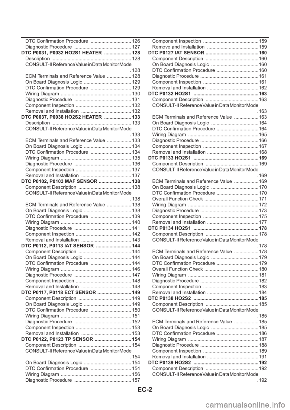
EC-2
DTC Confirmation Procedure ...............................126
Diagnostic Procedure ...........................................127
DTC P0031, P0032 HO2S1 HEATER .....................128
Description ............................................................128
CONSULT-II Reference Value in Data Monitor Mode
.128
ECM Terminals and Reference Value ...................128
On Board Diagnosis Logic ....................................129
DTC Confirmation Procedure ...............................129
Wiring Diagram .....................................................130
Diagnostic Procedure ...........................................131
Component Inspection ..........................................132
Removal and Installation ......................................132
DTC P0037, P0038 HO2S2 HEATER .....................133
Description ............................................................133
CONSULT-II Reference Value in Data Monitor Mode
.133
ECM Terminals and Reference Value ...................133
On Board Diagnosis Logic ....................................134
DTC Confirmation Procedure ...............................134
Wiring Diagram .....................................................135
Diagnostic Procedure ...........................................136
Component Inspection ..........................................137
Removal and Installation ......................................137
DTC P0102, P0103 MAF SENSOR .........................138
Component Description ........................................138
CONSULT-II Reference Value in Data Monitor Mode
.138
ECM Terminals and Reference Value ...................138
On Board Diagnosis Logic ....................................138
DTC Confirmation Procedure ...............................139
Wiring Diagram .....................................................140
Diagnostic Procedure ...........................................141
Component Inspection ..........................................142
Removal and Installation ......................................143
DTC P0112, P0113 IAT SENSOR ...........................144
Component Description ........................................144
On Board Diagnosis Logic ....................................144
DTC Confirmation Procedure ...............................144
Wiring Diagram .....................................................146
Diagnostic Procedure ...........................................147
Component Inspection ..........................................148
Removal and Installation ......................................148
DTC P0117, P0118 ECT SENSOR ..........................149
Component Description ........................................149
On Board Diagnosis Logic ....................................149
DTC Confirmation Procedure ...............................150
Wiring Diagram .....................................................151
Diagnostic Procedure ...........................................152
Component Inspection ..........................................153
Removal and Installation ......................................153
DTC P0122, P0123 TP SENSOR ............................154
Component Description ........................................154
CONSULT-II Reference Value in Data Monitor Mode
.154
On Board Diagnosis Logic ....................................154
DTC Confirmation Procedure ...............................154
Wiring Diagram .....................................................156
Diagnostic Procedure ...........................................157Component Inspection ..........................................159
Remove and Installation .......................................159
DTC P0127 IAT SENSOR ........................................160
Component Description ........................................160
On Board Diagnosis Logic ....................................160
DTC Confirmation Procedure ................................160
Diagnostic Procedure ............................................161
Component Inspection ..........................................161
Removal and Installation .......................................162
DTC P0132 HO2S1 ................................................ .163
Component Description ........................................163
CONSULT-II Reference Value in Data Monitor Mode
.163
ECM Terminals and Reference Value ...................163
On Board Diagnosis Logic ....................................164
DTC Confirmation Procedure ................................164
Wiring Diagram .....................................................165
Diagnostic Procedure ............................................166
Component Inspection ..........................................167
Removal and Installation .......................................168
DTC P0133 HO2S1 ................................................ .169
Component Description ........................................169
CONSULT-II Reference Value in Data Monitor Mode
.169
ECM Terminals and Reference Value ...................169
On Board Diagnosis Logic ....................................170
DTC Confirmation Procedure ................................170
Overall Function Check .........................................171
Wiring Diagram .....................................................172
Diagnostic Procedure ............................................173
Component Inspection ..........................................175
Removal and Installation .......................................177
DTC P0134 HO2S1 ................................................ .178
Component Description ........................................178
CONSULT-II Reference Value in Data Monitor Mode
.178
ECM Terminals and Reference Value ...................178
On Board Diagnosis Logic ....................................179
DTC Confirmation Procedure ................................179
Overall Function Check .........................................180
Wiring Diagram ....................................................
.181
Diagnostic Procedure ............................................182
Component Inspection ..........................................183
Removal and Installation .......................................184
DTC P0138 HO2S2 ................................................ .185
Component Description ........................................185
CONSULT-II Reference Value in Data Monitor Mode
.185
ECM Terminals and Reference Value ...................185
On Board Diagnosis Logic ....................................185
DTC Confirmation Procedure ................................186
Wiring Diagram .....................................................187
Diagnostic Procedure ............................................188
Component Inspection ..........................................189
Removal and Installation .......................................191
DTC P0139 HO2S2 ................................................ .192
Component Description ........................................192
CONSULT-II Reference Value in Data Monitor Mode
.192
Page 353 of 3833
EC-3
C
D
E
F
G
H
I
J
K
L
M
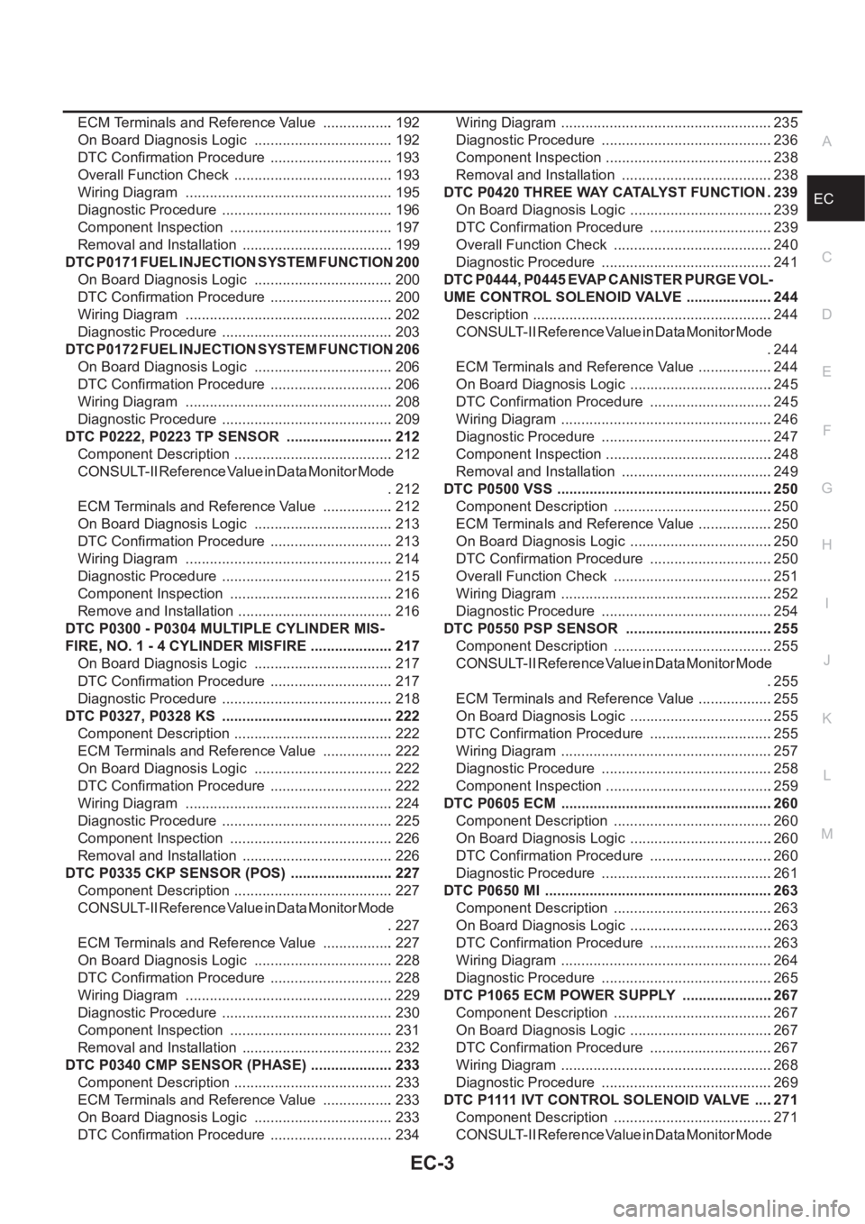
ECA ECM Terminals and Reference Value .................. 192
On Board Diagnosis Logic ................................... 192
DTC Confirmation Procedure ............................... 193
Overall Function Check ........................................ 193
Wiring Diagram .................................................... 195
Diagnostic Procedure ........................................... 196
Component Inspection ......................................... 197
Removal and Installation ...................................... 199
DTC P0171 FUEL INJECTION SYSTEM FUNCTION . 200
On Board Diagnosis Logic ................................... 200
DTC Confirmation Procedure ............................... 200
Wiring Diagram .................................................... 202
Diagnostic Procedure ........................................... 203
DTC P0172 FUEL INJECTION SYSTEM FUNCTION . 206
On Board Diagnosis Logic ................................... 206
DTC Confirmation Procedure ............................... 206
Wiring Diagram .................................................... 208
Diagnostic Procedure ........................................... 209
DTC P0222, P0223 TP SENSOR ........................... 212
Component Description ........................................ 212
CONSULT-II Reference Value in Data Monitor Mode
. 212
ECM Terminals and Reference Value .................. 212
On Board Diagnosis Logic ................................... 213
DTC Confirmation Procedure ............................... 213
Wiring Diagram .................................................... 214
Diagnostic Procedure ........................................... 215
Component Inspection ......................................... 216
Remove and Installation ....................................... 216
DTC P0300 - P0304 MULTIPLE CYLINDER MIS-
FIRE, NO. 1 - 4 CYLINDER MISFIRE ..................... 217
On Board Diagnosis Logic ................................... 217
DTC Confirmation Procedure ............................... 217
Diagnostic Procedure ........................................... 218
DTC P0327, P0328 KS ........................................... 222
Component Description ........................................ 222
ECM Terminals and Reference Value .................. 222
On Board Diagnosis Logic ................................... 222
DTC Confirmation Procedure ............................... 222
Wiring Diagram .................................................... 224
Diagnostic Procedure ........................................... 225
Component Inspection ......................................... 226
Removal and Installation ...................................... 226
DTC P0335 CKP SENSOR (POS) .......................... 227
Component Description ........................................ 227
CONSULT-II Reference Value in Data Monitor Mode
. 227
ECM Terminals and Reference Value .................. 227
On Board Diagnosis Logic ................................... 228
DTC Confirmation Procedure ............................... 228
Wiring Diagram .................................................... 229
Diagnostic Procedure ........................................... 230
Component Inspection ......................................... 231
Removal and Installation ...................................... 232
DTC P0340 CMP SENSOR (PHASE) ..................... 233
Component Description ........................................ 233
ECM Terminals and Reference Value .................. 233
On Board Diagnosis Logic ................................... 233
DTC Confirmation Procedure ............................... 234Wiring Diagram .....................................................235
Diagnostic Procedure ...........................................236
Component Inspection ..........................................238
Removal and Installation ......................................238
DTC P0420 THREE WAY CATALYST FUNCTION . 239
On Board Diagnosis Logic ....................................239
DTC Confirmation Procedure ...............................239
Overall Function Check ........................................240
Diagnostic Procedure ...........................................241
DTC P0444, P0445 EVAP CANISTER PURGE VOL-
UME CONTROL SOLENOID VALVE ......................244
Description ............................................................244
CONSULT-II Reference Value in Data Monitor Mode
.244
ECM Terminals and Reference Value ...................244
On Board Diagnosis Logic ....................................245
DTC Confirmation Procedure ...............................245
Wiring Diagram .....................................................246
Diagnostic Procedure ...........................................247
Component Inspection ..........................................248
Removal and Installation ......................................249
DTC P0500 VSS ......................................................250
Component Description ........................................250
ECM Terminals and Reference Value ...................250
On Board Diagnosis Logic ....................................250
DTC Confirmation Procedure ...............................250
Overall Function Check ........................................251
Wiring Diagram .....................................................252
Diagnostic Procedure ...........................................254
DTC P0550 PSP SENSOR .....................................255
Component Description ........................................255
CONSULT-II Reference Value in Data Monitor Mode
.255
ECM Terminals and Reference Value ...................255
On Board Diagnosis Logic ....................................255
DTC Confirmation Procedure ...............................255
Wiring Diagram .....................................................257
Diagnostic Procedure ...........................................258
Component Inspection ..........................................259
DTC P0605 ECM .....................................................260
Component Description ........................................260
On Board Diagnosis Logic ....................................260
DTC Confirmation Procedure ...............................260
Diagnostic Procedure ...........................................261
DTC P0650 MI .........................................................263
Component Description ........................................263
On Board Diagnosis Logic ....................................263
DTC Confirmation Procedure ...............................263
Wiring Diagram .....................................................264
Diagnostic Procedure ...........................................265
DTC P1065 ECM POWER SUPPLY .......................267
Component Description ........................................267
On Board Diagnosis Logic ....................................267
DTC Confirmation Procedure ...............................267
Wiring Diagram .....................................................268
Diagnostic Procedure ...........................................269
DTC P1111 IVT CONTROL SOLENOID VALVE .....271
Component Description ........................................271
CONSULT-II Reference Value in Data Monitor Mode
Page 354 of 3833
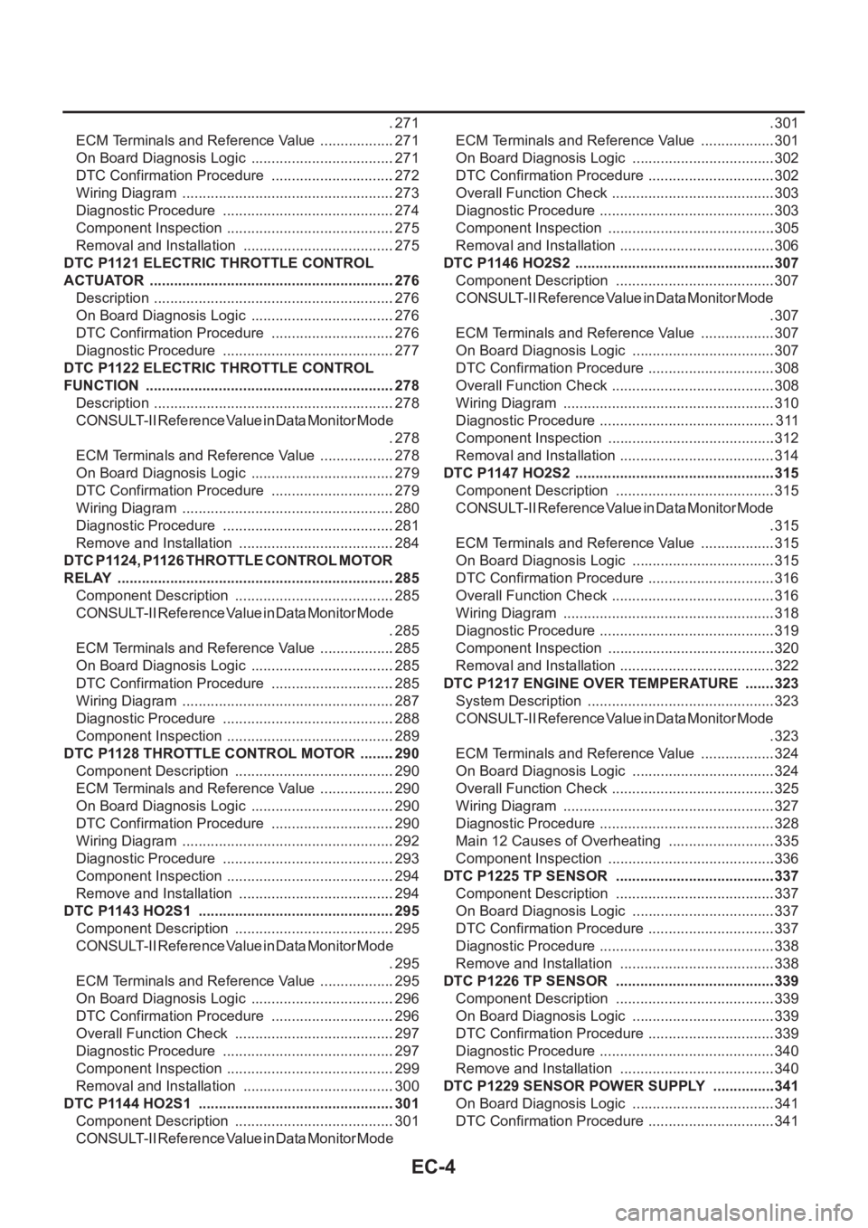
EC-4
.271
ECM Terminals and Reference Value ...................271
On Board Diagnosis Logic ....................................271
DTC Confirmation Procedure ...............................272
Wiring Diagram .....................................................273
Diagnostic Procedure ...........................................274
Component Inspection ..........................................275
Removal and Installation ......................................275
DTC P1121 ELECTRIC THROTTLE CONTROL
ACTUATOR .............................................................276
Description ............................................................276
On Board Diagnosis Logic ....................................276
DTC Confirmation Procedure ...............................276
Diagnostic Procedure ...........................................277
DTC P1122 ELECTRIC THROTTLE CONTROL
FUNCTION ..............................................................278
Description ............................................................278
CONSULT-II Reference Value in Data Monitor Mode
.278
ECM Terminals and Reference Value ...................278
On Board Diagnosis Logic ....................................279
DTC Confirmation Procedure ...............................279
Wiring Diagram .....................................................280
Diagnostic Procedure ...........................................281
Remove and Installation .......................................284
DTC P1124, P1126 THROTTLE CONTROL MOTOR
RELAY .....................................................................285
Component Description ........................................285
CONSULT-II Reference Value in Data Monitor Mode
.285
ECM Terminals and Reference Value ...................285
On Board Diagnosis Logic ....................................285
DTC Confirmation Procedure ...............................285
Wiring Diagram .....................................................287
Diagnostic Procedure ...........................................288
Component Inspection ..........................................289
DTC P1128 THROTTLE CONTROL MOTOR .........290
Component Description ........................................290
ECM Terminals and Reference Value ...................290
On Board Diagnosis Logic ....................................290
DTC Confirmation Procedure ...............................290
Wiring Diagram .....................................................292
Diagnostic Procedure ...........................................293
Component Inspection ..........................................294
Remove and Installation .......................................294
DTC P1143 HO2S1 .................................................295
Component Description ........................................295
CONSULT-II Reference Value in Data Monitor Mode
.295
ECM Terminals and Reference Value ...................295
On Board Diagnosis Logic ....................................296
DTC Confirmation Procedure ...............................296
Overall Function Check ........................................297
Diagnostic Procedure ...........................................297
Component Inspection ..........................................299
Removal and Installation ......................................300
DTC P1144 HO2S1 .................................................301
Component Description ........................................301
CONSULT-II Reference Value in Data Monitor Mode .301
ECM Terminals and Reference Value ...................301
On Board Diagnosis Logic ....................................302
DTC Confirmation Procedure ................................302
Overall Function Check .........................................303
Diagnostic Procedure ............................................303
Component Inspection ..........................................305
Removal and Installation .......................................306
DTC P1146 HO2S2 ..................................................307
Component Description ........................................307
CONSULT-II Reference Value in Data Monitor Mode
.307
ECM Terminals and Reference Value ...................307
On Board Diagnosis Logic ....................................307
DTC Confirmation Procedure ................................308
Overall Function Check .........................................308
Wiring Diagram .....................................................310
Diagnostic Procedure ............................................311
Component Inspection ..........................................312
Removal and Installation .......................................314
DTC P1147 HO2S2 ..................................................315
Component Description ........................................315
CONSULT-II Reference Value in Data Monitor Mode
.315
ECM Terminals and Reference Value ...................315
On Board Diagnosis Logic ....................................315
DTC Confirmation Procedure ................................316
Overall Function Check .........................................316
Wiring Diagram .....................................................318
Diagnostic Procedure ............................................319
Component Inspection ..........................................320
Removal and Installation .......................................322
DTC P1217 ENGINE OVER TEMPERATURE ........323
System Description ...............................................323
CONSULT-II Reference Value in Data Monitor Mode
.323
ECM Terminals and Reference Value ...................324
On Board Diagnosis Logic ....................................324
Overall Function Check .........................................325
Wiring Diagram .....................................................327
Diagnostic Procedure ............................................328
Main 12 Causes of Overheating ...........................335
Component Inspection ..........................................336
DTC P1225 TP SENSOR ........................................337
Component Description ........................................337
On Board Diagnosis Logic ....................................337
DTC Confirmation Procedure ................................337
Diagnostic Procedure ............................................338
Remove and Installation .......................................338
DTC P1226 TP SENSOR ........................................339
Component Description ........................................339
On Board Diagnosis Logic ....................................339
DTC Confirmation Procedure ................................339
Diagnostic Procedure ............................................340
Remove and Installation .......................................340
DTC P1229 SENSOR POWER SUPPLY ................341
On Board Diagnosis Logic ....................................341
DTC Confirmation Procedure ................................341
Page 355 of 3833
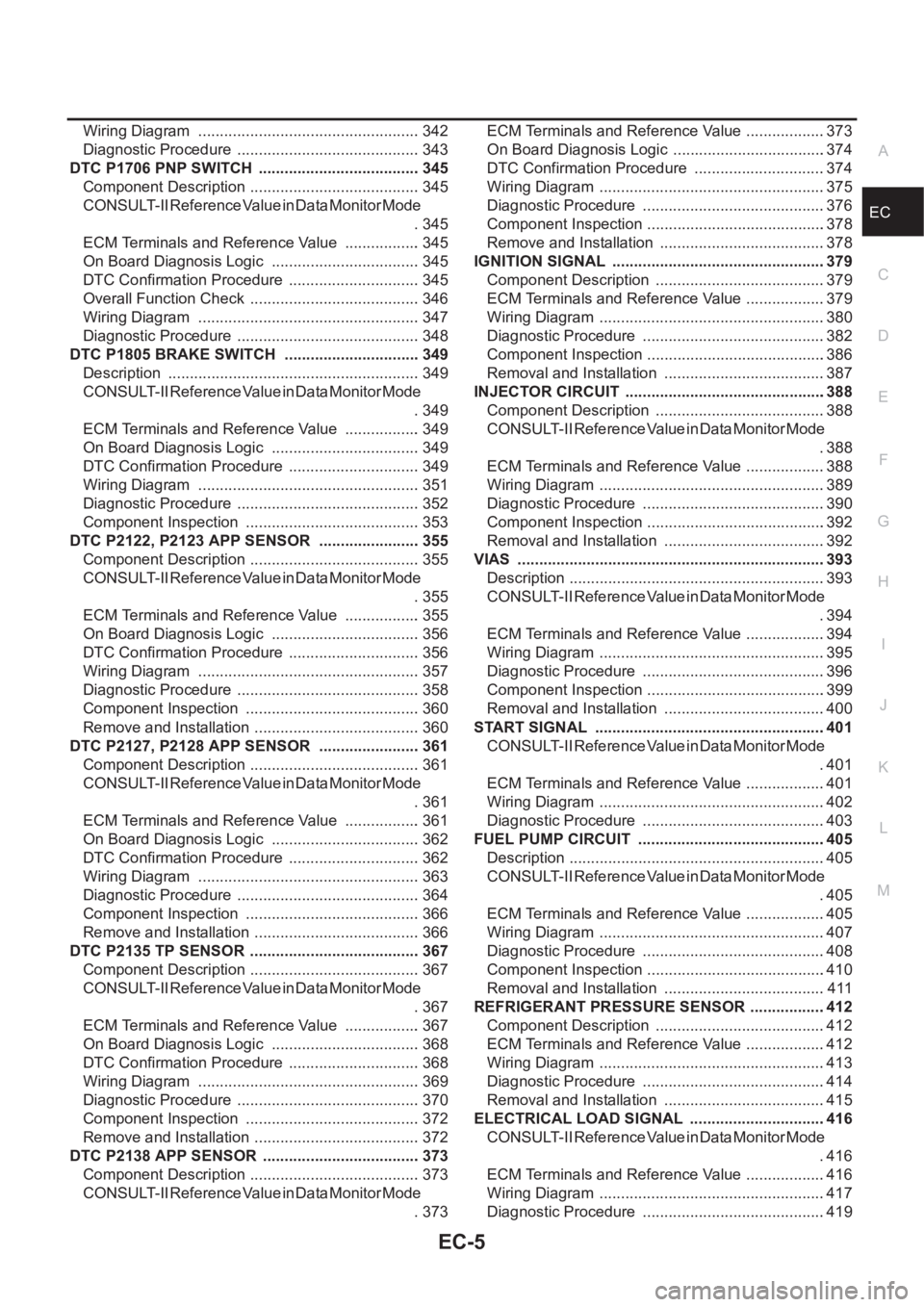
EC-5
C
D
E
F
G
H
I
J
K
L
M
ECA Wiring Diagram .................................................... 342
Diagnostic Procedure ........................................... 343
DTC P1706 PNP SWITCH ...................................... 345
Component Description ........................................ 345
CONSULT-II Reference Value in Data Monitor Mode
. 345
ECM Terminals and Reference Value .................. 345
On Board Diagnosis Logic ................................... 345
DTC Confirmation Procedure ............................... 345
Overall Function Check ........................................ 346
Wiring Diagram .................................................... 347
Diagnostic Procedure ........................................... 348
DTC P1805 BRAKE SWITCH ................................ 349
Description ........................................................... 349
CONSULT-II Reference Value in Data Monitor Mode
. 349
ECM Terminals and Reference Value .................. 349
On Board Diagnosis Logic ................................... 349
DTC Confirmation Procedure ............................... 349
Wiring Diagram .................................................... 351
Diagnostic Procedure ........................................... 352
Component Inspection ......................................... 353
DTC P2122, P2123 APP SENSOR ........................ 355
Component Description ........................................ 355
CONSULT-II Reference Value in Data Monitor Mode
. 355
ECM Terminals and Reference Value .................. 355
On Board Diagnosis Logic ................................... 356
DTC Confirmation Procedure ............................... 356
Wiring Diagram .................................................... 357
Diagnostic Procedure ........................................... 358
Component Inspection ......................................... 360
Remove and Installation ....................................... 360
DTC P2127, P2128 APP SENSOR ........................ 361
Component Description ........................................ 361
CONSULT-II Reference Value in Data Monitor Mode
. 361
ECM Terminals and Reference Value .................. 361
On Board Diagnosis Logic ................................... 362
DTC Confirmation Procedure ............................... 362
Wiring Diagram .................................................... 363
Diagnostic Procedure ........................................... 364
Component Inspection ......................................... 366
Remove and Installation ....................................... 366
DTC P2135 TP SENSOR ........................................ 367
Component Description ........................................ 367
CONSULT-II Reference Value in Data Monitor Mode
. 367
ECM Terminals and Reference Value .................. 367
On Board Diagnosis Logic ................................... 368
DTC Confirmation Procedure ............................... 368
Wiring Diagram ................................................
.... 369
Diagnostic Procedure ........................................... 370
Component Inspection ......................................... 372
Remove and Installation ....................................... 372
DTC P2138 APP SENSOR ..................................... 373
Component Description ........................................ 373
CONSULT-II Reference Value in Data Monitor Mode
. 373ECM Terminals and Reference Value ...................373
On Board Diagnosis Logic ....................................374
DTC Confirmation Procedure ...............................374
Wiring Diagram .....................................................375
Diagnostic Procedure ...........................................376
Component Inspection ..........................................378
Remove and Installation .......................................378
IGNITION SIGNAL ..................................................379
Component Description ........................................379
ECM Terminals and Reference Value ...................379
Wiring Diagram .....................................................380
Diagnostic Procedure ...........................................382
Component Inspection ..........................................386
Removal and Installation ......................................387
INJECTOR CIRCUIT ...............................................388
Component Description ........................................388
CONSULT-II Reference Value in Data Monitor Mode
.388
ECM Terminals and Reference Value ...................388
Wiring Diagram .....................................................389
Diagnostic Procedure ...........................................390
Component Inspection ..........................................392
Removal and Installation ......................................392
VIAS ........................................................................393
Description ............................................................393
CONSULT-II Reference Value in Data Monitor Mode
.394
ECM Terminals and Reference Value ...................394
Wiring Diagram .....................................................395
Diagnostic Procedure ...........................................396
Component Inspection ..........................................399
Removal and Installation ......................................400
START SIGNAL ......................................................401
CONSULT-II Reference Value in Data Monitor Mode
.401
ECM Terminals and Reference Value ...................401
Wiring Diagram .....................................................402
Diagnostic Procedure ...........................................403
FUEL PUMP CIRCUIT ............................................405
Description ............................................................405
CONSULT-II Reference Value in Data Monitor Mode
.405
ECM Terminals and Reference Value ..................
.405
Wiring Diagram .....................................................407
Diagnostic Procedure ...........................................408
Component Inspection ..........................................410
Removal and Installation ......................................411
REFRIGERANT PRESSURE SENSOR ..................412
Component Description ........................................412
ECM Terminals and Reference Value ...................412
Wiring Diagram .....................................................413
Diagnostic Procedure ...........................................414
Removal and Installation ......................................415
ELECTRICAL LOAD SIGNAL ................................416
CONSULT-II Reference Value in Data Monitor Mode
.416
ECM Terminals and Reference Value ...................416
Wiring Diagram .....................................................417
Diagnostic Procedure ...........................................419